

Page 1
BeltGuardKit
DH200SeriesLawnTractor
ModelNo.1 11-6032
Donotsupplytheseinstructionstothecustomer.
TheseinstructionsareforadealertoinstalladditionalbeltguardsmandatedbytheFrenchgovernment.
FormNo.3373-761RevA
InstallationInstructions
Safety
Important:Refertothe
youareunfamiliarwithoperatingthismachine
beforeproceeding.Themanualcontainsimportant
informationaboutsafelyoperatingthemachine.
Ifyoudonotknowthisinformation,youcould
seriouslyinjureyourselforothers.
Important:Youwillneedtodrillholesinthe
machinetoinstallthiskit.Alwaysweareye
protectionwhenyoudrill.
SafetyandInstructional
Decals
Safetydecalsandinstructionsareeasily
visibletotheoperatorandarelocated
nearanyareaofpotentialdanger.
Replaceanydecalthatisdamagedor
lost.
Operator's Man ual
Installation
if
1
PreparingforInstallation
NoPartsRequired
Procedure
1.Parkthemachineonalevel,smoothsurfacewith
sufcientspacetoaccessbothsidesofthemowing
deck.
2.Lowerthemowingdecktotheshortestcutting
height.
3.Stoptheengine,waitforallmovingpartstostop,set
theparkingbrake,removetheignitionkeyfromthe
ignitionswitch,anddisconnectthespark-plugwire.
120-1119
1.Firehazard—readtheOperator'sManual.
©2012—TheToro®Company
8111LyndaleAvenueSouth
Bloomington,MN55420
Registeratwww.T oro.com.
CAUTION
Ifyouleavethekeyintheignitionswitch,
someonecouldaccidentlystarttheengineand
seriouslyinjureyouorotherbystanders.
Removethekeyfromtheignitionswitchand
disconnectthewirefromthesparkplugbefore
youinstallthekit.Setthewireasidesothatit
doesnotaccidentallycontactthesparkplug.
4.Raisetherearofthemachineofftheground,support
bothendsoftherearaxlewithjackstands,and
removebothrearwheels.
OriginalInstructions(EN)
PrintedintheCzechRepublic
AllRightsReserved
Page 2
2
G018544
1
2
3
4
5
6
3
7
4
8
G018545
1
2
3
4
5
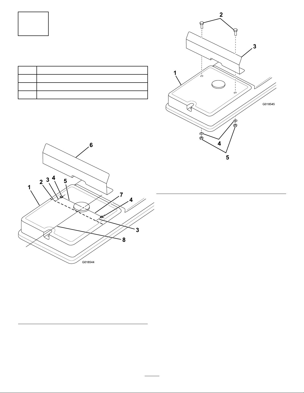
InstallingtheDeckGuard
Partsneededforthisprocedure:
1Deck-belt-coverguard
2
Bolt(M5x12)
2
Washer(M5.3)
2
Locknut(M5)
Procedure
1.Placethedeck-belt-coverguardontothedeck-belt
coverwhereitistobeinstalled,andmarkits
position;referto
Figure1.
Figure2
1.Deck-beltcover4.Washers
2.Bolts5.Nuts
3.Deck-belt-coverguard
Figure1
Drawingnottoscale
1.Deck-beltcover5.Approximately9.5cm
2.Markthepositionofthe
deck-belt-coverguard
here.
3.Approximately2.0cm7.Approximately9.0cm
4.Drillahole(6.0mm)here.8.Centerline
6.Deck-belt-coverguard
2.Drill2holes(6mmdiameter)inthetopofthe
deck-beltcoverinthelocationsshowninFigure1.
4.Raisethedecktothehighestcuttingheightto
verifythatthedeck-belt-coverguardclearsallwires,
switches,andbelts,andthatitwillnotinterferewhen
youoperatethemachineorthecuttingdeck.
3.Securethedeck-belt-coverguardtothedeck-belt
coverwith2bolts,2washers,and2nutsasshown
inFigure2.
2
Page 3

3
G018547
2
3
1
G018548
1
2
3
4
InstallingtheLeft-BeltGuard
Partsneededforthisprocedure:
1
Left-beltguard
8
Self-tappingscrew
Figure4
Procedure
1.Lowerthemowingdecktotheshortestcutting
height.
2.Useamountingbracketasatemplateanddrill2holes
(3.6mmdiameter)intheframeontheleft-handside
ofthemachineinthelocationsshownin
Figure3
1.Self-tappingscrews3.Drillholes(3.6mm
diameter)here.
2.Mountingbrackets
Figure3.
1.Drillahole(3.4mm
diameter)intheframe
here.
2.Left-beltguard4.Drillahole(3.6mm
3.Self-tappingscrew(6)
diameter)inthesupport
brackethere.
5.Drillahole(3.6mmdiameter)atthelocationyou
markedonthesupportbracket.
6.Securetheleft-beltguardtotheleft-handsideofthe
machineusingself-tappingscrewsintheexisting
holesinthemachineasshownin
Figure4.
7.Drillahole(3.4mmdiameter)intheleft-handside
oftheframeusingtheremainingholeintheleft-belt
guardasatemplate;referto
Figure4.
8.Insertaself-tappingscrewintheholeandnish
securingtheleft-beltguardtotheframe;referto
Figure4.
9.Raisethedecktothehighestcuttingheighttoverify
thattheleft-beltguardclearsallwires,switches,and
belts,andthatitwillnotinterferewhenyouoperate
themachineorthecuttingdeck.
3.Installthemountingbrackets(Figure3).
4.Placetheleft-beltguardontotheleft-handsideof
themachine(whereitistobeinstalled),lineupthe
holes,andmarkthelocationonthesupportbracket
whereyouneedtodrillahole;referto
Figure4.
3
Page 4

4
G018549
1
2
3
4
InstallingtheRight-BeltGuard
Partsneededforthisprocedure:
1Right-beltguard
1
Self-tappingscrew
Procedure
1.Lowerthemowingdecktotheshortestcutting
height.
2.Placetheright-beltguardontotheright-handsideof
themachine(whereitistobeinstalled),lineupthe
holes,andmarkthelocationonthesupportbracket
whereyouneedtodrillahole;referto
Figure5.
Figure5
1.Self-tappingscrew3.Useexistingfastenerson
2.Right-beltguard
3.Drillahole(3.6mmdiameter)atthelocationyou
markedonthesupportbracket.
4.Securetheright-beltguardtotheright-handside
ofthemachineusingaself-tappingscrewandthe
existingfastenersonthemachineasshownin
Figure5.
5.Raisethedecktothehighestcuttingheighttoverify
thattheright-beltguardclearsallwires,switches,and
belts,andthatitwillnotinterferewhenyouoperate
themachineorthecuttingdeck.
themachinetosecure
theguardattheseplaces
here.
4.Drillahole(3.6mm
diameter)here.
4
 Loading...