

Page 1

Form No. 3356-423 Rev A
Recycler® Kit
For Z334 Z Master® Mowers
Model No. 110-9960
Installation Instructions
Note: Deter mine the left and right sides of the mac hine from the nor mal operating position.
Safety
Side Discharge or Mulch
Grass
W ithout the g rass deflector , discharge
co v er , or complete g rass catcher assembl y
mounted in place, y ou and other s ar e
exposed to blade contact and thr o wn de bris.
Contact with r otating mo w er blade(s) and
thr o wn de bris will cause injur y or death.
• Nev er r emo v e the g rass deflector fr om
the mo w er because the g rass deflector
r outes material do wn to w ard the turf.
If the g rass deflector is ev er dama ged,
r eplace it immediatel y .
• Nev er put y our hands or feet under the
mo w er .
• Nev er tr y to clear the discharge ar ea or
mo w er blades unless y ou disenga ge the
po w er tak e of f (PT O) lev er and tur n the
ignition k ey to of f. Also r emo v e the k ey
and pull the wir e of f the spar k plug(s).
Ensure the mo w er has the hing ed g rass deflector
that disperses clippings to the side and do wn
to w ard the turf , while in side disc harg e mode .
T o m ulc h g rass clippings , the baffles m ust be
installed into the mo w er as sho wn in the follo wing
ste ps .
© 2006—The Toro® Company
8111 Lyndale Avenue South
Bloomington, MN 55420
Register at www.Toro.com. Original Instructions (EN)
Printed in the USA.
All Rights Reserved
Page 2
Installation
Loose Parts
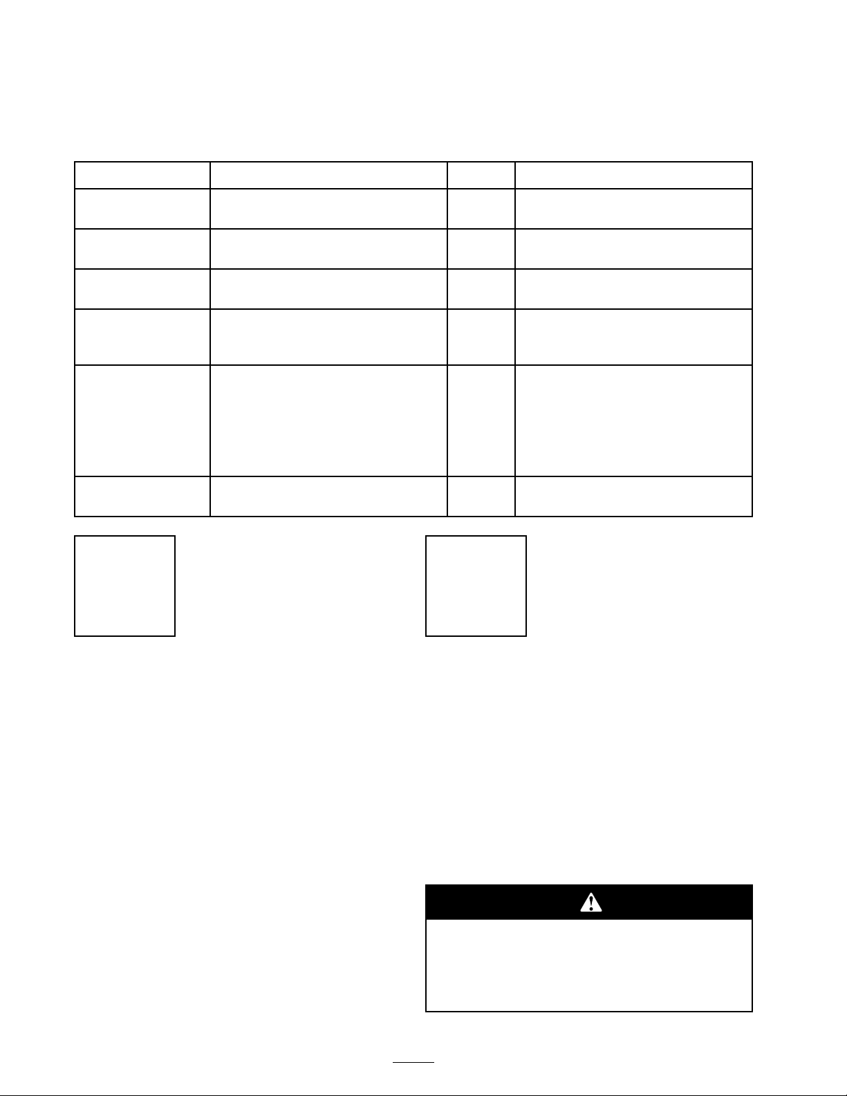
Use the chart below to verify that all parts have been shipped.
Step
1
2
3
4
5
6
No parts required
No parts required
No parts required
Discharge plate
Bolt (3/8 x 1 inch)
Flange nut (3/8 inch)
Left bafe
Right bafe
Angle support
Bolt (3/8 x 3/4 inch)
Flange nut (3/8 inch)
Bolt (3/8 x 1 inch)
Recycler blades
Description
Step
Qty.
–
–
–
1
2
1
1
1
1
6
6
2
2
Prepare the mower.
Remove the existing blades.
Remove the existing bafes.
Install the discharge plate.
Install the bafes.
Install the new blades.
Step
Use
1
Preparing the Mower
No Parts Required
Procedure
1. T horoughly clean mo w er dec k. All debris m ust
be remo v ed to ensure baffles will fit properly
ag ainst mo w er dec k.
2. R e pair all bent or damag ed areas of mo w er
dec k and re place any missing par ts .
2
Removing the Existing
Blades
No Parts Required
Procedure
R emo v e the existing blades from the spindles
( Figure 1 ).
Note: Sa v e the blades for use when in side
disc harging mode . Use the blade bolt and cur v ed
w asher for installing the recycler blades .
A blade is shar p . Contact with shar p blade
can cause serious per sonal injur y .
W ear g lo v es or wrap shar p edges of the
blade with a ra g .
2
Page 3
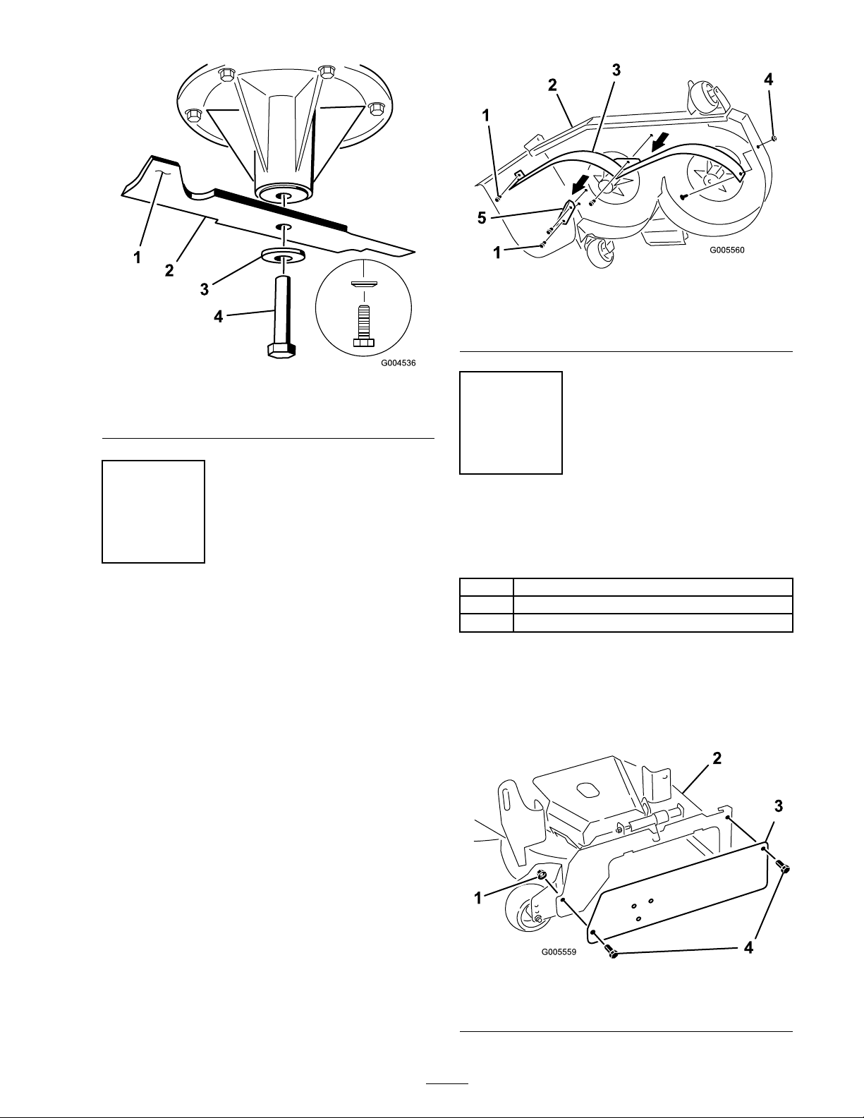
Figure 2
1. Bolt 4. Lock Nut
2. Mower deck 5. Discharge bafe
3. Front bafe
Figure 1
1. Sail area of blade 3. Curved washer
2. Blade 4. Blade bolt
Step
3
Removing the Existing
Bafes
No Parts Required
Procedure
Note: In the ste ps belo w , the bolts are threaded
into the mo w er dec k. R emo v e the n uts first before
remo ving bolts .
1. R emo v e the mo w er belt co v ers from the
mo w er dec k.
Step
4
Installing the Discharge
Plate
Parts needed for this step:
1
Discharge plate
2
Bolt (3/8 x 1 inch)
1
Flange nut (3/8 inch)
Procedure
Install the disc harg e plate to the outside of the
mounting brac k et with 2 bolts (3/8 x 1 inc h) and 2
flang e n uts (3/8 inc h) ( Figure 3 ).
2. R emo v e the bolts , w ashers and flang e n uts
holding the front baffle in place ( Figure 2 ).
3. R emo v e the bolts and flang e n uts holding the
disc harg e baffle in place ( Figure 2 ).
Note: Sa v e the baffles and hardw are for use
when c hanging to side disc harging mode .
3
1. Flange nut
(3/8 inch)
Figure 3
2. Mower
deck
3. Discharge
plate
4. Bolt (3/8 x
1 inch)
Page 4
Step
5
Installing the Bafes
3. P osition the baffles into the mo w er .
4. Loosely install the baffles to the top of the
mo w er dec k with 2 bolts (3/8 x 1 inc h) ( Figure
5 ).
5. Loosely install the baffles to the disc harg e plate
with a bolt (3/8 x 3/4 inc h) and a flang e n ut
(3/8 inc h) ( Figure 5 ).
Parts needed for this step:
1
Left bafe
1
Right bafe
1
Angle support
6
Bolt (3/8 x 3/4 inch)
6
Flange nut (3/8 inch)
2
Bolt (3/8 x 1 inch)
Procedure
Note: All holes exist in the mo w er dec k for
installing the new baffles .
Note: Loosely install the baffles to align the
baffles with all existing holes in the mo w er .
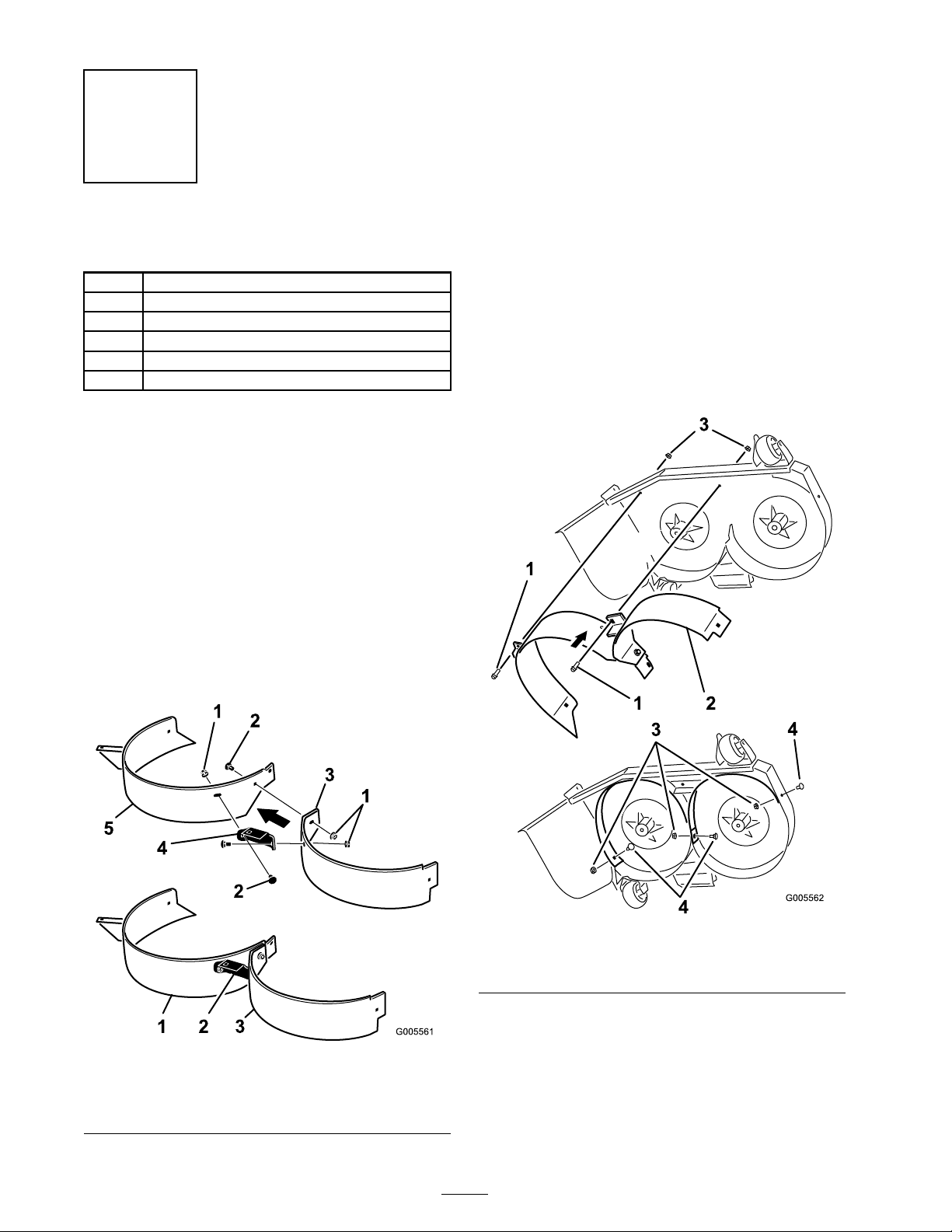
1. Loosely install the angle suppor t to the left and
right baffles with 2 car riag e bolts (3/8 x 3/4
inc h) and 2 flang e n uts (3/8 inc h) ( Figure 4 ).
2. Loosely install the left and right baffle tog ether
with a car riag e bolt (3/8 x 3/4 inc h) and a
flang e n ut (3/8 inc h) ( Figure 4 ).
6. Loosely install the baffles to the side of the
mo w er dec k with a bolt (3/8 x 3/4 inc h) and a
flang e n ut (3/8 inc h) ( Figure 5 ).
7. Loosely install the baffles to the center of the
mo w er dec k with a bolt (3/8 x 3/4 inc h) and a
flang e n ut (3/8 inc h) ( Figure 5 ).
8. Tighten all fasteners .
1. Flange nut (3/8 inch)
2. Bolt (3/8 x 1 inch)
3. Left bafe
Figure 4
4. Angle support
5. Right bafe
Figure 5
1. Bolt (3/8 x 1 inch) 3. Flange nut (3/8 inch)
2. Bafes
4
4. Bolt (3/8 x 3/4 inch)
Page 5
Step
6
Installing the New Blades
Parts needed for this step:
2
Recycler blades
Procedure
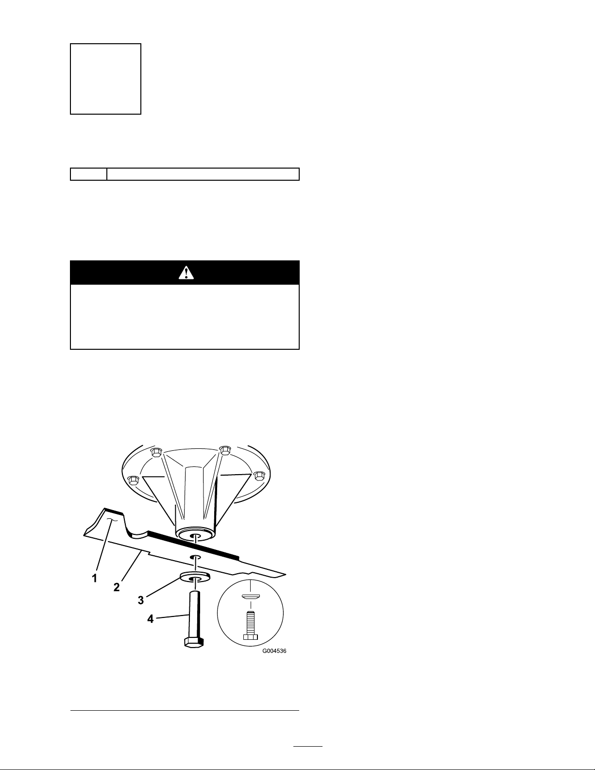
Important: T he sail par t of the blade (i.e.,
the tur ned up section) must f ace the inside of
the mo w er ( Figur e 6 ).
A blade is shar p . Contact with shar p blade
can cause serious per sonal injur y .
W ear g lo v es or wrap shar p edges of the
blade with a ra g .
3. Carefully rotate eac h blade to v erify there is a
1/16 inc h (1.6 mm) g ap betw een the end of
the blade and the baffles . If a blade contacts a
baffle , loosen the fasteners and position the
baffles to increase clearance betw een the end
of the blade and baffle .
4. Tighten the fasteners and c hec k for blade
clearance ag ain.
1. Place the blade onto the spindle shaft ( Figure
6 ).
2. Install the spring disk and blade bolt. T he
spring disk cone m ust be installed to w ard the
bolt head ( Figure 6 ). T or que the blade bolt to
85-110 ft-lb (115-150 N•m).
Figure 6
1. Sail Area of Blade 4. Blade Bolt
2. Blade 5. Cone Towards Bolt Head
3. Spring Disk
5
Page 6

Operation
Selecting the Proper
Height-of-Cut
R emo v e appro ximately one inc h or no more
than 1/3 of the g rass blade when cutting . In
ex ce ptionally lush and dense g rass y ou ma y need
to raise the height-of-cut setting or con v er t to side
disc harg e or bag ging operations .
Mowing in Extreme
Conditions
Air is required to cut and recut g rass clippings in
the mo w er housing, so do not set the height-of-cut
too lo w or totally sur round the housing b y uncut
g rass . Alw a ys tr y to ha v e one side of the mo w er
housing free from uncut g rass , allo wing air to be
dra wn into the housing . W hen making an initial
cut through the center of an uncut area, operate
the mac hine slo w er and bac k up if the mo w er
star ts to clog .
If residue is allo w ed to build up in the mo w er
housing, cutting perfor mance will decrease .
Mowing at Proper Intervals
Under most nor mal conditions y ou will need to
mo w ev er y 4–5 da ys . Ho w ev er , g rass g ro ws at
different rates at different times . T hus , in order
to maintain the same height-of-cut, whic h is a
g ood practice , y ou’ll need to cut more frequently
in early spring; as the g rass g ro wth rate slo ws in
mid summer , cut only ev er y 8–10 da ys . If y ou
are unable to mo w for an extended period due to
w eather conditions or other reasons , con v er t to
side disc harg e or bag ging options or mo w first
with the height-of-cut at a high lev el; then mo w
ag ain 2–3 da ys later with a lo w er height setting .
Mowing with Sharp Blades
A shar p blade cuts cleanly and without tearing or
shredding the g rass . A dull blade will tear and
shred the g rass . T earing and shredding causes the
g rass to tur n bro wn at the edg es whic h impairs
g ro wth and increases susce ptibility to disease .
After Operating
T o ensure optim um perfor mance , clean the
underside of the mo w er housing after eac h use .
6
Page 7

Page 8

 Loading...