

Page 1
KawasakiEngineConversionKit,Suzuki-Powered
Heavy-DutyLawnMowerswithZoneStart
ModelNo.110-4996
Installation
LooseParts
Usethechartbelowtoverifythatallpartshavebeenshipped.
FormNo.3360-287RevA
InstallationInstructions
ProcedureDescription
1
2
Nopartsrequired
Beltcover(74-1770)
Engine(106-0844)
Decal(110-0520)
Screws(95-1727)
Key(5-1077)
Spacer-retainer(103-3795)
Bladebolt(105-8579)
Tankbracket(106-0908-03)
Fueltankcap(93-7198)
Screw(95-1726)
Screw(104-2628)
Fuelhose(109-0296)
Fuellter(71-9280)
Clamp(2412-98)
Fuelhose(109-0650)
Cabletie(3290-378)
Throttlecontrol(108-2645)
Brakecable(1 14-3483)
Throttlecable(106-0888)
Shoulderscrew(94-9422)
Nut(32128-27)
Qty.
Use
–
1
1
1
4
1
1
1
1
1
2
3
1
1
4
1
4
1
1
1
1
1
Removetheoldengine.
Installthenewengine.
1
RemovingtheOldEngine
NoPartsRequired
Procedure
Important:Saveallfastenersthatyouremovedfor
reuseunlessotherwisenoted.
1.Drainthefuelfromthefueltank.
©2008—TheToro®Company
8111LyndaleA venueSouth
Bloomington,MN55420
Registeratwww.T oro.com.
2.Removetheoldbeltcoveranddiscardit.
3.Removeanddiscardthethrottlecontrolcableand
thebladebrakecable.
4.Removeanddiscardtheoldfuelhose,fuellter,
andclamp.
5.Removethebladebolt,washer,bladestiffener,blade
retainer,andspacer.
6.Removethebeltfromthedriverpulley;inspectthe
beltforwearandreplaceitifnecessary.
7.Removetheenginemountingbolts.
8.Removetheoldenginefromthemowerhousing.
OriginalInstructions(EN)
PrintedintheUSA
AllRightsReserved
Page 2
9.Removethefueltankfromthetankbaseandretain
itforreuse.
10.Replacethefueltankcapwithanewcapprovidedin
thekit;discardtheoldfueltankcap.
11.Removeanddiscardthedischargetunneldoor.
12.Cleanthemowerhousingandcheckitfordamage
andwear.
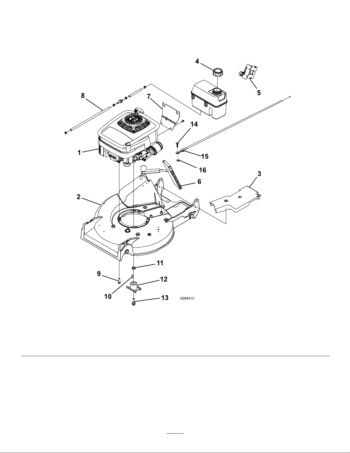
Figure1
1.Kawasakiengine5.Throttlecontrol
2.Mowerdeck6.Dischargedoor
3.Beltcover7.Tankbracket11.Bladeretainerspacer15.Brakecable
4.Fueltankcap
8.Fuelhose,fuellter,and
clamps
9.Enginemountingbolt(4)
10.Squarekey14.Shoulderscrew
12.Bladeretainer16.Flangenut
2
13.Bladebolt
Page 3
Note:T orquethebladeboltto45–60ft-lb.
Note:Centerthecrankshaftprotectoronthe
2
crankshaftandtorquethefastenersto180–250in-lb.
InstallingtheNewEngine
Partsneededforthisprocedure:
1
Beltcover(74-1770)
1
Engine(106-0844)
1
Decal(110-0520)
4
Screws(95-1727)
1
Key(5-1077)
1
Spacer-retainer(103-3795)
1
Bladebolt(105-8579)
1
Tankbracket(106-0908-03)
1
Fueltankcap(93-7198)
2
Screw(95-1726)
3
Screw(104-2628)
1
Fuelhose(109-0296)
1
Fuellter(71-9280)
4
Clamp(2412-98)
1
Fuelhose(109-0650)
4
Cabletie(3290-378)
1
Throttlecontrol(108-2645)
1
Brakecable(114-3483)
1
Throttlecable(106-0888)
1
Shoulderscrew(94-9422)
1
Nut(32128-27)
6.Attachthenewfuelhose,fuellter,andclamptothe
engineandthefueltank.
Note:Theshorthoseattachestothefueltank.
7.Installandadjustthenewthrottlecontrolcableand
thebladebrakecable.
Note:Routethethrottlecontrolcableandblade
brakecablethroughthesamearea.Usetheshoulder
screw(94-9422)andthenut(32128-27)tosecure
thebladebrakecabletotheengineinthefollowing
order:shoulderscrew ,brakecable,brakearm(on
engine),andangenut.
8.Replacethebeltcover.
Procedure
Note:RefertoFigure1forinstallingthenewengine.
1.Installthenewdooronthedischargetunnel.
2.Installthefueltank(withthenewfueltankcap)
onthetankbasewiththe2screwsyoupreviously
removed.
Note:Securethetankbracketwith3fasteners
(fromtheloosepartsbag)anduseblueLoctite(242).
3.Installthenewengineonthemowerhousing.
Note:Torquetheenginemountingboltsto
200–250in-lb.
4.Installthebeltonthedriverpulley(self-propelled
modelsonly).
5.Installthebladebolt,washer,bladestiffener,blade
retainer,andspacer.
3
Page 4

Notes:
4
Page 5

KitdeconversiónamotoresKawasaki,
Cortacéspedesparaserviciopesadoconmotor
SuzukiconZonadearranque
Nºdemodelo110-4996
Instalación
Piezassueltas
Utilicelatablasiguienteparavericarquenofaltaningunapieza.
FormNo.3360-287RevA
InstruccionesdeInstalación
Procedimiento
1
2
Nosenecesitanpiezas
Cubiertadelacorrea(74-1770)
Motor(106-0844)
Pegatina(110-0520)
Tornillos(95-1727)
Chaveta(5-1077)
Espaciador–piezadesujeción
(103-3795)
Pernodelacuchilla(105-8579)
Soportedeldepósito(106-0908-03)
Tapóndeldepósitodecombustible
(93-7198)
Tornillo(95-1726)
Tornillo(104-2628)
Tubodecombustible(109-0296)
Filtrodecombustible(71-9280)
Abrazadera(2412-98)
Tubodecombustible(109-0650)
Sujetacables(3290-378)
Controldelacelerador(108-2645)
Cabledefreno(114-3483)
Cabledelacelerador(106-0888)
Tornillodecuellolargo(94-9422)
Tuerca(32128-27)
DescripciónCant.
–
1
1
1
4
1
1
1
1
1
2
3
1
1
4
1
4
1
1
1
1
1
Retireelmotorantiguo.
Instaleelmotornuevo.
Uso
©2008—TheToro®Company
8111LyndaleA venueSouth
Bloomington,MN55420
Registresuproductoenwww.T oro.com.
Traduccióndeloriginal(ES)
ImpresoenEE.UU.
Reservadostodoslosderechos
Page 6

1
Cómoretirarelmotorantiguo
Nosenecesitanpiezas
Procedimiento
Importante:Guardetodoslosherrajesqueretiró
parasureutilización,amenosqueseespecique
locontrario.
1.Dreneelcombustibledeldepósitodecombustible.
2.Retirelacubiertadelacorreaantiguaydeséchela.
3.Retireydesecheelcabledecontroldelaceleradory
elcabledefrenodelacuchilla.
4.Retireydesecheeltubodecombustible,elltrode
combustible,ylaabrazaderaantiguos.
5.Retiredelejeelpernodelacuchilla,laarandela,el
refuerzodelacuchilla,lapiezadesujecióndela
cuchillayelespaciador.
6.Retirelacorreadelapoleadetransmisión;
inspeccionelacorreaycámbielasiestádesgastada.
7.Retirelospernosdemontajedelmotor.
8.Retireelmotorantiguodelacarcasadelsoplador.
9.Retireeldepósitodecombustibledelsoportedel
depósitoyguárdeloparasuusoposterior.
10.Cambieeltapóndeldepósitodecombustiblepor
eltapónnuevosuministradoconelkit;desecheel
tapóndeldepósitodecombustibleantiguo.
11.Retireydesechelapuertadelconductodedescarga.
12.Limpielacarcasadelcortacéspedycompruebeque
noestádañadanidesgastada.
2
Page 7

1.MotorKawasaki
2.Plataformadecorte
3.Cubiertadelacorrea7.Soportedeldepósito
4.Tapóndeldepósitode
combustible
5.Controldelacelerador
6.Puertadedescarga
8.Tubodecombustible,
ltrodecombustible,y
abrazaderas
Figura1
9.Pernodemontajedelmotor
(4)
10.Chavetacuadrada
11.Espaciadordelapiezade
sujecióndelacuchilla
12.Piezadesujecióndela
cuchilla
3
13.Pernodelacuchilla
14.Tornillodecuellolargo
15.Cabledelfreno
16.Tuercaconarandela
prensada
Page 8

2
Instalacióndelmotornuevo
5.Instaleelpernodelacuchilla,laarandela,elrefuerzo
delacuchilla,lapiezadesujecióndelacuchillayel
espaciador.
Nota:Aprieteelpernodelacuchillaa61–81Nm
(45–60pies-libra).
Piezasnecesariasenestepaso:
1
Cubiertadelacorrea(74-1770)
1
Motor(106-0844)
1
Pegatina(1 10-0520)
4
Tornillos(95-1727)
1
Chaveta(5-1077)
1
Espaciador–piezadesujeción(103-3795)
1
Pernodelacuchilla(105-8579)
1
Soportedeldepósito(106-0908-03)
1
Tapóndeldepósitodecombustible(93-7198)
2
Tornillo(95-1726)
3
Tornillo(104-2628)
1
Tubodecombustible(109-0296)
1
Filtrodecombustible(71-9280)
4
Abrazadera(2412-98)
1
Tubodecombustible(109-0650)
4
Sujetacables(3290-378)
1
Controldelacelerador(108-2645)
1
Cabledefreno(114-3483)
1
Cabledelacelerador(106-0888)
1
Tornillodecuellolargo(94-9422)
1
Tuerca(32128-27)
Nota:Centreelprotectordelcigüeñalsobreel
cigüeñalyaprietelosherrajesa20–28Nm(180–250
pulgadas-libra).
6.Conecteeltubodecombustible,elltrode
combustible,ylaabrazaderanuevosalmotoryal
depósitodecombustible.
Nota:Eltubocortoseconectaaldepósitode
combustible.
7.Instaleyajusteelnuevocabledecontroldel
aceleradoryelcabledefrenodelacuchilla.
Nota:Paseelcabledecontroldelaceleradoryel
cabledefrenodelacuchillaporelmismopunto.
Utiliceeltornillodecuellolargo(94-9422)ylatuerca
(32128-27)parajarelcabledefrenodelacuchilla
almotor,enelordensiguiente:tornillodecuello
largo,cabledefreno,muelledelbrazo(enelmotor)
ytuercaconarandelaprensada.
8.Vuelvaacolocarlacubiertadelacorrea.
Procedimiento
Nota:Paralainstalacióndelmotornuevo,consultela
Figura1.
1.Instalelapuertanuevaenelconductodedescarga.
2.Instaleeldepósitodecombustible(conelnuevo
tapóndeldepósitodecombustible)sobrelabasedel
depósitoconlos2tornillosqueretiróanteriormente.
Nota:Sujeteelsoportedeldepósitocon3herrajes
(delabolsadepiezassueltas)yutiliceLoctiteazul
(242).
3.Retireelmotorantiguodelacarcasadelsoplador.
Nota:Aprietelospernosdemontajedelmotora
23–28Nm(200–250pulgadas-libra).
4.Instalelacorreaenlapoleadetransmisión(modelos
autopropulsadossolamente).
4
 Loading...