

Page 1

Form No. 3354-892 Rev A
Replacement Rear Hinge Kit
For Model 78502 Finishing Kit
Model No. 110-3941
Installation Instructions
Note: Deter mine the left and right sides of the mac hine from the nor mal operating position.
Loose Parts
Use the chart below to verify that all parts have been shipped.
Step
1
2
3
No parts required
No parts required
New mounting plate
Bolt (3/8 x 1 inch)
Nut (3/8 inch)
Description
Step
1
Preparing the Mower
No Parts Required
Procedure
1. T horoughly clean mo w er dec k. All debris m ust
be remo v ed to ensure the mounting brac k et
will fit properly ag ainst mo w er dec k.
2. R e pair all bent or damag ed areas of mo w er
dec k and re place any missing par ts .
Qty.
–
–
1
2
2
Prepare the mower.
Remove the existing bracket and
gage wheel.
Install the new mounting plate.
Use
Step
2
Removing the Existing
Mounting Plate and Gage
Wheel
No Parts Required
Procedure
1. R emo v e the g ag e wheel from the existing
mounting plate ( Figure 1 ). Sa v e this hardw are .
2. R emo v e the existing mounting plate from the
mo w er dec k ( Figure 1 ). Sa v e this hardw are .
© 2005—The Toro® Company
8111 Lyndale Avenue South
Bloomington, MN 55420
Register at www.Toro.com. Original Instructions (EN)
Printed in the USA.
All Rights Reserved
Page 2
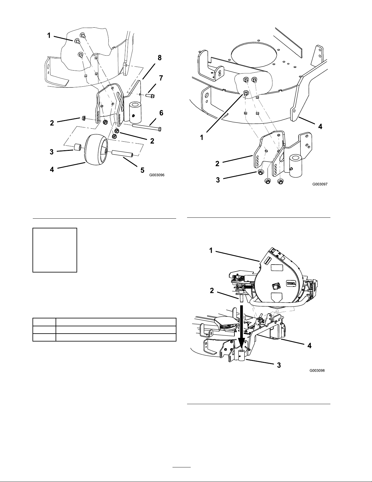
Figure 1
1. Carriage bolt
2. Flange nut 6. Bolt
3. Bushing 7. Tapping bolt
4. Gage wheel 8. Mounting plate
5. Spacer
Step
3
Installing the New Mounting
Plate
Parts needed for this step:
1
New mounting plate
2
Bolt (3/8 x 1 inch)
2
Nut (3/8 inch)
Procedure
Figure 2
1. Existing carriage bolt
2. New bracket 4. Mower deck
3. Existing nut (3/8 inch)
2. Install the blo w er into the new mounting plate
( Figure 3 ).
1. Install the new brac k et to the outside of the
mo w er dec k with the 3 existing bolts and n uts
previously remo v ed ( Figure 2 ).
Do not tighten these bolts . T hese will be
tightened after the blo w er is installed.
Figure 3
1. Blower assembly 3. Mounting plate
2. Blower assembly peg 4. Mower deck
3. Close the blo w er and latc h the front of the
blo w er to the mo w er dec k.
4. Tighten the 3 bolts holding the new mounting
plate to the mo w er dec k ( Figure 2 ).
2
Page 3

5. Unlatc h the blo w er and remo v e it from the
mounting plate and mo w er .
6. Mark and center punc h the locations for the
tw o holes in the mounting plate ( Figure 4 ).
7. R emo v e the mounting plate and drill tw o
13/32 inc h diameter holes ( Figure 4 ).
Figure 5
1. Existing carriage bolt 4. Mower deck
2. New mounting plate
3. Flange nut (3/8 inch)
5. Bolt (3/8 x 1 inch)
Figure 4
1. Drill 13/32 inch diameter
holes here
2. New mounting plate
8. Install the new brac k et to the outside of the
mo w er dec k with the 3 existing bolts and 2
new bolts (3/8 x 1 inc h) and 2 n uts (3/8 inc h)
( Figure 5 ).
9. Install the previously remo v ed g ag e wheel to
the new mounting plate ( Figure 6 ).
Figure 6
1. Bushing 4. Bolt
2. Gage wheel 5. New mounting plate
3. Spacer
3
Page 4

 Loading...