


Form No. 3353–604 Rev B
DFS Bagger Adapter Kit
for Mounting 2005 and After Baggers on 2004 and Before
Z500 Series Z Masters
Part No. 110–0350
Installation Instructions
Note: Use the existing hardware that came with the bagger to install the bagger mounting bracket in Step 3.
Setup
Note: Determine the left and right sides of the machine from the normal operating position.
Loose Parts
Note: Use the chart below to verify all parts have been shipped.
Step
1
2
3
4
5
6
Description Qty. Use
No parts needed Removing the Drive Wheels
No parts needed
Side bracket—right
Side bracket—left
Stiffener bracket
Bolt, 3/8 x 1 inch
Flange Nut, 3/8 inch
Curved washer
Spacer
No parts needed Tightening all mounting bolts
No parts needed Installing the Drive Wheels
1
1
2
6
6
6
4
Removing the Roll Over Protection
System (ROPS)
Installing bagger mounting bracket
Installing the side brackets to the
machine
W 2005 by The Toro Company
8111 Lyndale Avenue South
Bloomington, MN 55420-1196
Original Instructions (Language abbreviation)
Contact us at www.Toro.com
All Rights Reserved
Printed in the USA
Step
1
No parts needed for this step.
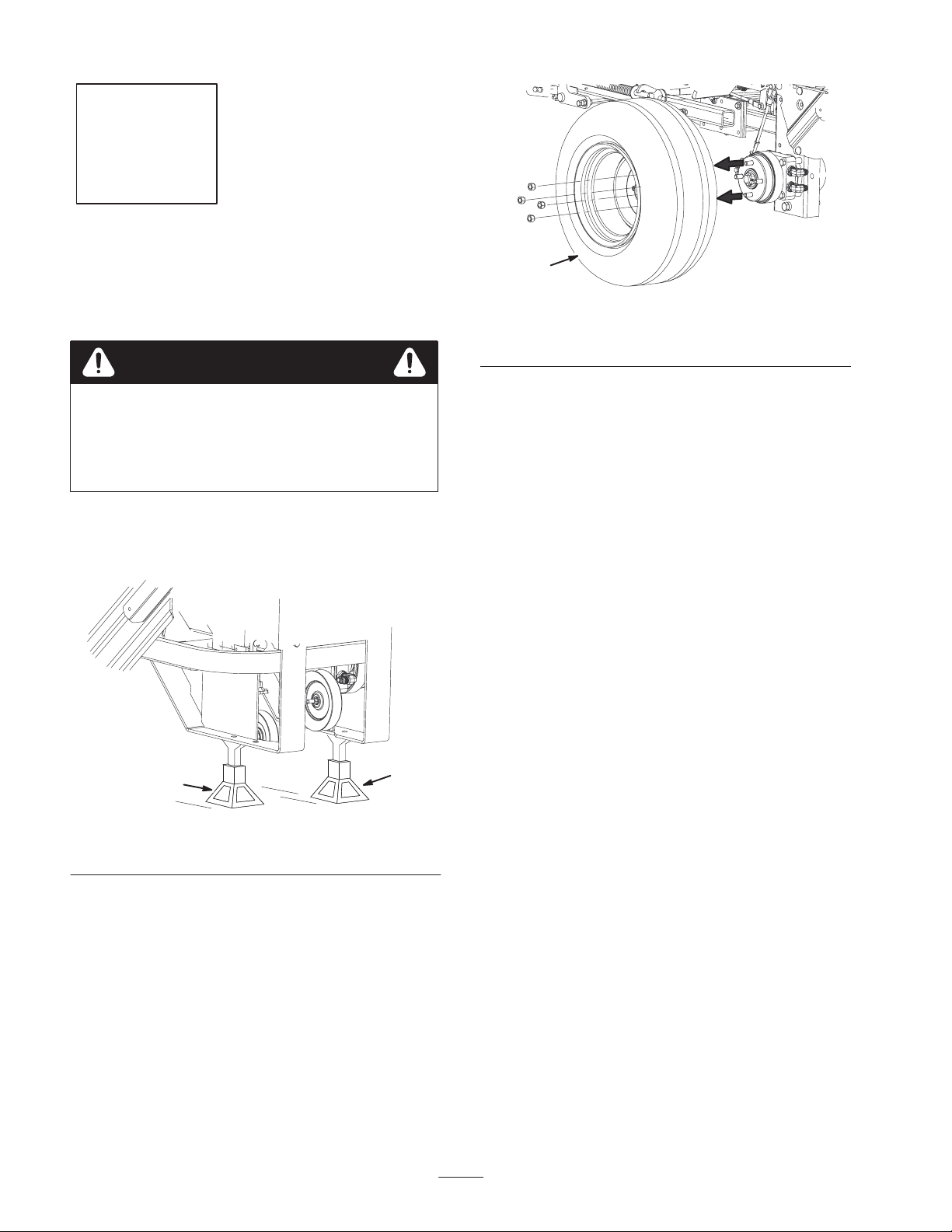
Removing the Drive Wheels
Danger
Mechanical or hydraulic jacks may fail to support
machine and cause a serious injury.
• Use jack stands when supporting machine.
• Do not use hydraulic jacks.
1. Loosen the drive wheel nuts.
2. Raise the rear of the machine and support with jack
stands (Fig. 1).
1
m–6859
Figure 2
1. Drive wheel
1
Figure 1
1. Jack stand
3. Remove the nuts and the drive wheels (Fig. 2).
1
2
Step
2
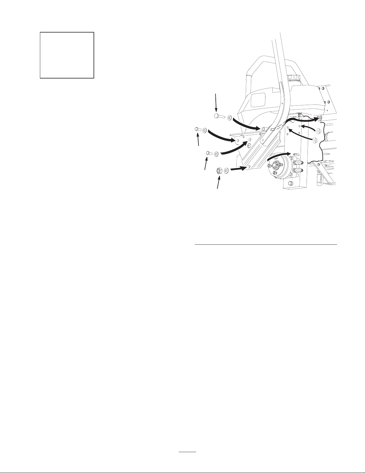
No parts needed for this step.
Removing the Roll Over
Protection System (ROPS)
Remove the following fasteners (Fig. 3) securing each
(right and left) roll bar section to the frame:
• Lock nut (3/8 inch) and curved washer. Do not
remove bolt from frame.
• Bolt (3/8 x 1 inch), curved washer and flange nut
(3/8 inch).
• Bolt (3/8 x 1 inch), curved washer and flange nut
(3/8 inch).
• Bolt (3/8 x 4-1/2 inches), curved washer and
flange nut (3/8 inch).
3
2
2
1
1. Lock nut, 3/8 inch &
curved washer
2. Bolt, 3/8 x 1 inch, curved
washer & flange nut,
3/8 inch (2)
m–6854
Figure 3
3. Bolt, 3/8 x 4–1/2 inches,
curved washer & flange
nut, 3/8 inch
3

Step
3
3. In the bottom hole, install a bolt (3/8 x 1–1/4 inch) and
a flange nut (3/8 in.) (Fig. 4).
4. Install a bracket stiffener to the side bracket and bagger
mounting bracket. Use 4 bolts (3/8 x 3/4 inch) and
4 flange nuts (3/8 in.) (Fig. 4).
5. Repeat the previous steps for the opposite side.
6
Parts needed for this step:
• 1 Side bracket—right
• 1 Side bracket—left
• 2 Stiffener brackets
Note: Use the existing hardware that came with the bagger
to install the bagger mounting bracket.
If you have a liquid cooled machine, go to page 5 for
Installing the Bagger Mounting Bracket onto a Liquid
Cooled Machine.
If you have an air cooled machine, use the following
instructions for Installing the Bagger Mounting Bracket
onto a Air Cooled Machine.
Installing the Bagger Mounting
Bracket onto an Air Cooled
Machine
Important Do not tighten any bolts until both side
brackets and bagger mounting bracket are fit loose on the
machine.
1
9
8
1. Bagger mounting bracket
2. Bolt, 3/8 x 1–1/4 inch
3. Flange nut, 3/8 inch
4. Bracket stiffener
5. Left side bracket
5
4
3
2
Figure 4
3
7
4
3
6
6. Bolt, 3/8 x 3/4 inch
7. Long frame spacer
8. Bolt, 3/8 x 1–1/2 inch
9. Short frame spacer
10. Right side bracket
10
m–5978
Refer to Tightening the Mounting Bolts, on page 7, for the
correct procedure to tighten the bolts.
Installing the Bagger Mounting Bracket to
the Side Brackets (Air Cooled)
Important When installing the bagger bracket for an
air cooled machine, use only 2 long frame spacers; 1 per
each side (Fig. 4).
1. Install the side brackets to the bagger mounting bracket
(Fig. 4).
2. In the top two holes, install 2 bolts (3/8 x 1–1/2 inch),
2 flange nuts (3/8 in.) one long frame spacer, and one
short frame spacer (Fig. 4).
Note: Make sure the long frame spacers are installed as
shown in figure 4.
Installing the Bagger Mounting Bracket
onto an Air Cooled Machine
Important When installing the bagger onto an air
cooled machine, use the air cooled spacer (Fig. 5).
1. Pull the bottom of the roll bar away from the frame and
slide the side braket between the machine frame and the
ROPS frame (Fig. 3). Repeat for the opposite side of the
machine.
2. Install the bagger mounting bracket to the rear frame of
the machine (Fig. 5).
3. In the top two holes, install 2 bolts (3/8 x 1–3/4 inch),
2 flange nuts (3/8 in.) and the air cooled frame spacer
(Fig. 5).
4

4. In the bottom two holes, install 2 bolts (3/8 x
6
1–1/4 inch) and 2 flange nuts (3/8 in.) (Fig. 5).
Note: Make sure the long frame spacers are installed as
shown in Figure 6.
4
5
3
3
1
3
6
2
6
2
m–5863
Figure 5
1. Bagger mounting bracket
2. Bolt, 3/8 x 1–1/4 inch
3. Flange nut, 3/8 inch
4. Bumper
5. Air cooled frame spacer
6. Bolt, 3/8 x 1–3/4 inch
Installing the Bagger Mounting
Bracket onto a Liquid Cooled
Machine
Important Do not tighten any bolts until both side
brackets and bagger mounting bracket are fit loose on the
machine.
Refer to Tightening the Mounting Bolts, on page 7, for the
correct procedure to tighten the bolts.
3. In the bottom hole, install a bolt (3/8 x 1–1/4 inch) and
a flange nut (3/8 in.) (Fig. 6).
4. Install a bracket stiffener to the side bracket and bagger
mounting bracket. Use 4 bolts (3/8 x 3/4 inch) and
4 flange nuts (3/8 in.) (Fig. 6).
5. Repeat the previous steps for the opposite side.
5
4
10
3
4
3
7
3
7
1
9
6
8
2
m–5979
Figure 6
1. Bagger mounting bracket
2. Bolt, 3/8 x 1–1/4 inch
3. Flange nut, 3/8 inch
4. Bracket stiffener
5. Left side bracket
6. Bolt, 3/8 x 3/4 inch
7. Long frame spacer
8. Bolt, 3/8 x 1–1/2 inch
9. Short frame spacer
10. Right side bracket
Installing the Bagger Mounting Bracket to
the Side Brackets (Liquid Cooled)
Important When installing the bagger onto a liquid
cooled machine, the rear bumper plate must be removed.
Use 4 long frame spacers for this installation, 2 per each
side (Fig. 6).
1. Install the side brackets to the bagger mounting bracket
(Fig. 6).
2. In the top two holes, install 2 bolts (3/8 x 1–1/2 inch),
2 flange nuts (3/8 in.), 2 long frame spacers, and one
short frame spacer (Fig. 6).
Installing the Bagger Mounting Bracket
onto a Liquid Cooled Machine
1. Pull the bottom of the roll bar away from the frame and
slide the side braket between the machine frame and the
ROPS frame (Fig. 3). Repeat for the opposite side of the
machine.
2. Install the bagger mounting bracket to the rear frame of
the machine (Fig. 7).
3. In the top two holes, install 2 bolts (3/8 x 1–3/4 inch)
and 2 flange nuts (3/8 in.) (Fig. 7).
4. In the bottom two holes, install 2 bolts (3/8 x
1–1/4 inch) and 2 flange nuts (3/8 in.) (Fig. 7).
5

4
3
2
3
• Bolt (3/8 x 1–1/2 inch), curved washer, spacer and
flange nut (3/8 inch) (New).
1
5
2
5
2
1. Bagger mounting bracket
2. Bolt, 3/8 x 1–1/4 inch
3. Flange nut, 3/8 inch
Step
4
Figure 7
3
4. Bumper
5. Bolt, 3/8 x 1–3/4 inch
m–5864
• Bolt (3/8 x 1–1/2 inch), curved washer and
flange nut (3/8 inch) (New).
• Bolt (3/8 x 1–1/2 inch), curved washer and
flange nut (3/8 inch) (New).
Note: Make sure the curved washers and spacers are
installed as shown in figure 8.
Note: Hydraulic lines may need to be adjusted when
installing the side brackets onto the machine. This will
allow for fastener clearance.
4
6
5
6
32
Parts needed for this step:
• 6 Bolts, 3/8 x 1–1/2 inch
• 6 Flange Nuts, 3/8 inch
• 6 Curved washers
• 4 Spacers
Installing the Side Brackets to
the Machine
Important Do not tighten any bolts until both side
brackets and bagger mounting bracket are fit loose on the
machine.
Refer to Tightening the Mounting Bolts, on page 7, for the
correct procedure to tighten the bolts.
1. Install the bagger side plates and the roll bar sections
(Fig. 8) to each side of the mower using the following
fasteners:
• Lock nut (3/8 inch) and curved washer (Previously
removed).
• Bolt (3/8 x 4-1/2 inches), curved washer, spacer and
flange nut (3/8 inch) (Previously removed).
1
1. Side bracket
2. Curved washer, 3/8 inch
3. Bolt, 3/8 x 1–1/2 inch
2
Figure 8
4. Flange nut, 3/8 inch
5. ROPS
6. Spacer
6

Step
Step
5
No parts needed for this step.
Tightening all Mounting Bolts
The following steps are the correct sequence to tighten the
side brackets and the bagger mounting bracket.
All 3/8 inch mounting bolts need to be torqued to 35 ft.–lb.
(48 Nwm).
1. Tighten the bagger mounting bracket to the rear frame
first (Figures 5 or 7).
2. Tighten the bagger mounting bracket to the side
brackets (Figures 4 or 6).
3. Tighten the bracket stiffeners to both the side plates and
the bagger mounting bracket (Figures 4 or 6).
4. Tighten the side brackets to the side of the mower
(Fig. 8).
6
No parts needed for this step.
Installing The Drive Wheels
1. Mount the wheels with the valve stem to the outside and
secure them with the nuts previously removed (Fig. 9).
2. Torque the nuts to 95 ft-lb (128 Nm).
1
2
Figure 9
1. Drive wheel 2. Nuts
m–6859
3. Lower the machine onto the drive wheels.
7

8
 Loading...