

Page 1
Form No. 3354-345 Rev A
Chain-Drive Hex Shaft Service Kit
Clutch-Drive Hex Shaft Service Kit
For 2005 and Before Power Max® Snowthrowers
Model No. 108-7317
Model No. 108-7318
Installation Instructions
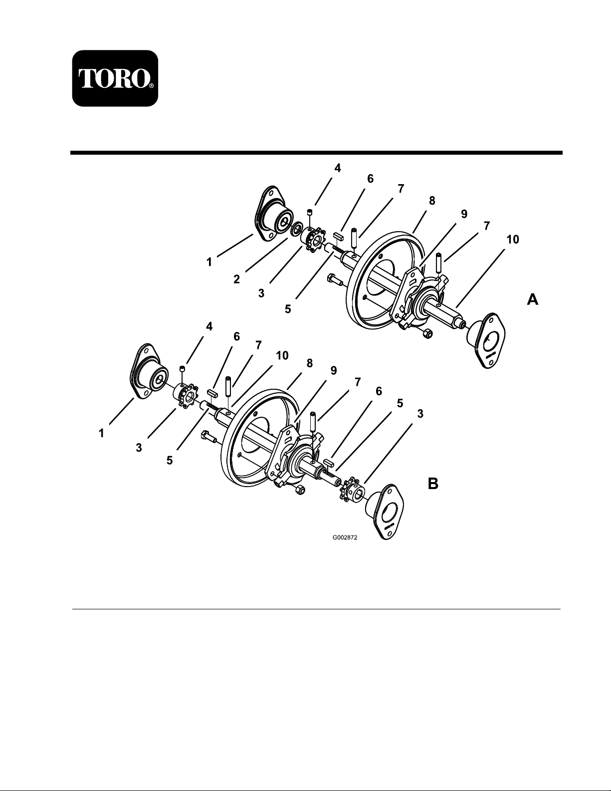
1. Bearing retainer (2)
2. Bushing spacer (chain drive
kit only)
3. Sprocket 6. Square key
4. Screw
5. Keyway
Instructions
Note: In Figure 1 abo v e , A is the c hain-dri v e hex
shaft ser vice kit and B is the clutc h-dri v e hex shaft
ser vice kit.
1. Disassemble the traction dri v e assembly .
Note: R efer to ser vice man ual 492-9138.
© 2005—The Toro® Company
8111 Lyndale Avenue South
Bloomington, MN 55420
Register at www.Toro.com. Original Instructions (EN)
Figure 1
7. Roll pin 10. Hex shaft
8. Rubber friction wheel
9. Hex trunnion
2. R emo v e the r ubber friction wheel from the
old hex shaft assembly (if y ou are using it with
the kit).
3. Mount the r ubber friction wheel on the new
hex tr unnion using the hardw are from the old
assembly , ensuring that the r ubber wheel is
oriented o v er the tr unnion.
Printed in the USA.
All Rights Reserved
Page 2

4. Apply a light coat of oil to the hex por tion of
the hex shaft.
5. Slide the r ubber friction wheel and hex
tr unnion assembly onto the hex shaft, ensuring
that the r ubber friction wheel is oriented on
the side closest to the k eyw a y (c hain-dri v e
model only).
6. Assemble the roll pins on the hex shaft with
the hex tr unnion assembly betw een them.
Note: T he roll pins should be centered on
the hex shaft.
7. Place the square k ey in the k eyw a y on the hex
shaft.
8. Assemble the sproc k et onto the hex shaft and
o v er the k ey .
Note: T he sproc k et should be flush ag ainst
the hex shaft shoulder and the k ey should not
protr ude bey ond the sproc k et.
9. Tighten the sproc k et to the hex shaft and
k eyw a y using the set screws pro vided. T or que
the screws to 60 to 80 in-lb .
10. R e peat ste ps 7 through 9 for the other end of
the hex shaft (clutc h-dri v e model only).
11. Assemble the spacer onto the sproc k et end of
the hex shaft (c hain-dri v e model only).
12. Inser t one of the bearing retainers through the
hole in the sno wthro w er frame and secure it to
the frame using the screws that y ou previously
remo v ed.
13. Inser t the end of the hex shaft assembly into
the bearing retainer so that the hex tr unnion is
on the right side of the r ubber friction wheel
( Figure 1 ).
14. Inser t the other bearing retainer through the
hole in the other side of the sno wthro w er
frame and capture the other end of the hex
shaft assembly with the bearing retainer .
15. Secure the bearing retainer to the sno wthro w er
frame using the screws that y ou previously
remo v ed.
16. Attac h the c hains and g rease the components .
17. Assemble the remaining traction dri v e
components .
Note: R efer to the ser vice man ual.
2
Page 3

Form No. 3354 -345 Rev A
Kit entretien d'arbre hexagonal
d'entraînement de chaîne Kit entretien
d'arbre hexagonal d'entraînement
d'embrayage
Déneigeuses Power Max® jusqu'à l'année 2005
N° de modèle 108 -7317
N° de modèle 108 -7318
Installation Instructions
1. Retenue de roulement (2)
2. Bague entretoise (kit
entraînement de chaîne
uniquement)
3. Pignon
© 2005—The Toro® Company
8111 Lyndale Avenue South
Bloomington, MN 55420
Figure 1
4. Vis
5. Rainure de clavette 8. Roue de friction en
6. Clavette carrée 9. Tourillon hexagonal
Enregistrez votre produit à www.Toro.com
7. Goupille cylindrique 10. Arbre hexagonal
caoutchouc
Traduction du texte d'origine (FR)
Imprimé aux États -Unis.
Tous droits réservés
Page 4

Instructions
Remarque: Dans le Figure 1 ci -dessus , A
re présente le kit d'entretien d'arbre hexag onal
d'entraînement de c haîne , et B re présente le kit
d'entretien d'arbre hexag onal d'entraînement
d'embra yag e .
1. Démontez l'ensemble transmission aux roues .
Remarque: R e por tez -v ous au man uel
d'entretien 492 -9138.
2. Déposez la roue de friction en caoutc houc
de l'ancien ensemble arbre hexag onal (si v ous
allez l'utiliser a v ec le kit).
3. Montez la roue de friction en caoutc houc sur
le nouv eau tourillon hexag onal à l'aide des
fixations de l'ancien ensemble . La roue de
friction doit être tour née v ers le tourillon.
4. Appliquez une fine couc he d'huile sur la par tie
hexag onale de l'arbre .
5. F aites coulisser l'ensemble roue de friction
en caoutc houc et tourillon hexag onal sur
l'arbre hexag onal. La roue de friction doit être
tour née du côté le plus près de la rain ure de
la cla v ette (modèle à entraînement de c haîne
uniquement).
12. Insérez une des reten ues de roulement dans le
trou du c hâssis de la déneig euse et fix ez -la au
c hâssis a v ec les vis retirées précédemment.
13. Insérez l'extrémité de l'ensemble arbre
hexag onal dans la reten ue du roulement de
sor te que le tourillon hexag onal se trouv e du
côté dr oit de la roue de friction en caoutc houc
( Figure 1 ).
14. Insérez l'autre reten ue de roulement dans le
trou de l'autre côté du c hâssis de la déneig euse
et bloquez l'autre extrémité de l'ensemble arbre
hexag onal a v ec la reten ue de roulement.
15. Fix ez la reten ue de roulement au c hâssis
de la déneig euse à l'aide des vis retirées
précédemment.
16. Fix ez les c haînes et g raissez les composants .
17. Assemblez les autres composants de la
transmission aux roues .
Remarque: R e por tez -v ous au man uel
d'entretien.
6. Montez les g oupilles cylindriques sur l'arbre
hexag onal et placez l'ensemble tourillon
hexag onal entre elles .
Remarque: Les g oupilles cylindriques
doi v ent être centrées sur l'arbre hexag onal.
7. Placez la cla v ette car rée dans la rain ure sur
l'arbre hexag onal.
8. Montez le pignon sur l'arbre hexag onal et par
dessus la cla v ette .
Remarque: Le pignon doit être en butée
contre l'épaulement de l'arbre hexag onal et la
cla v ette ne doit pas dépasser au -delà du pignon.
9. Ser rez le pignon sur l'arbre hexag onal et la
cla v ette à l'aide des vis de montag e four nies .
Ser rez les vis à 7 -9 Nm.
10. Répétez les étapes 7 à 9 à l'autre extrémité
de l'arbre hexag onal (modèle à entraînement
d'embra yag e uniquement).
11. Montez l'entretoise sur l'extrémité pignon de
l'arbre hexag onal (modèle à entraînement de
c haîne uniquement).
2
 Loading...