

Page 1
Form No. 3352-971
Chute Ring Kit
For Power Shift and Power Throw XL Snowthrowers
Part No. 108-7308
Installation Instructions
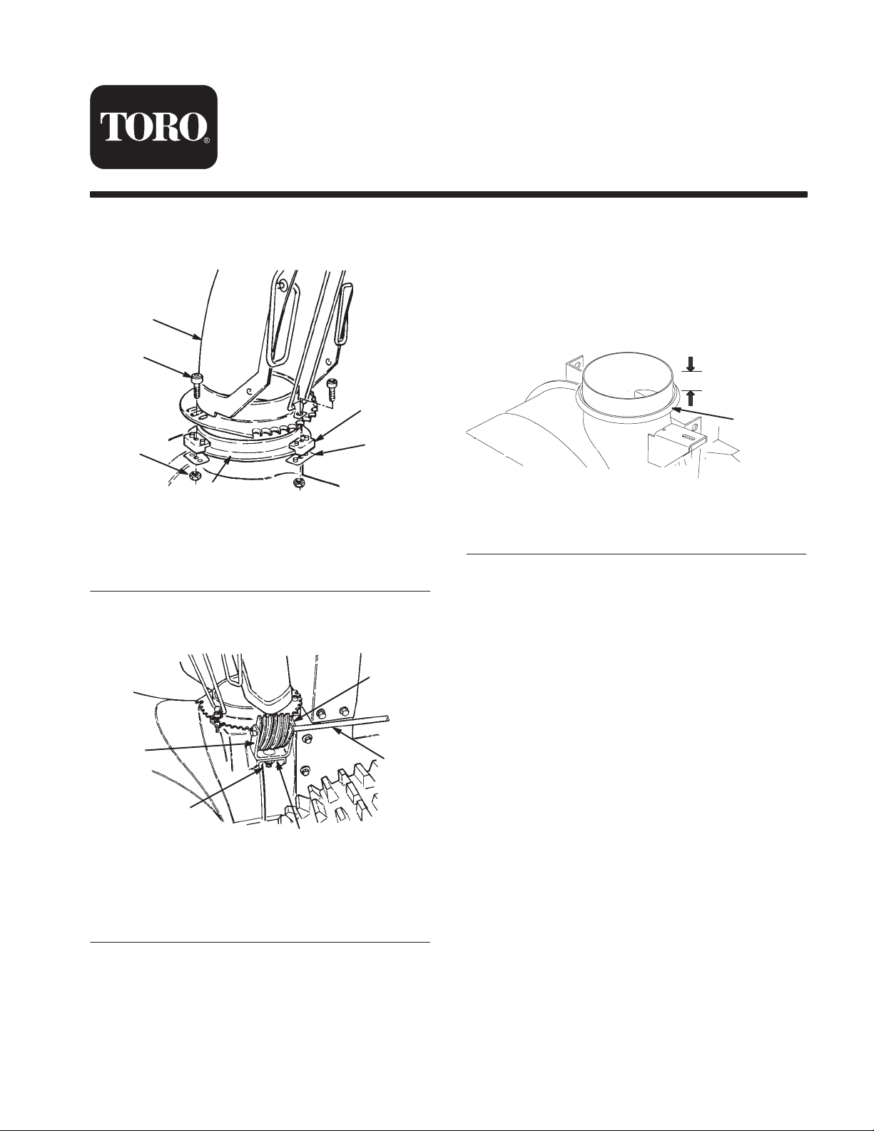
1. Remove the chute assembly by removing the chute
retainers, chute retainer plates, screws, and locknuts
(Fig. 1).
1
5
2
6
3
m-168
4
Figure 1
1. Discharge chute
2. Chute retainer (3)
3. Chute retainer plate (3)
4. Chute ring
5. Screw (3)
6. Locknut (3)
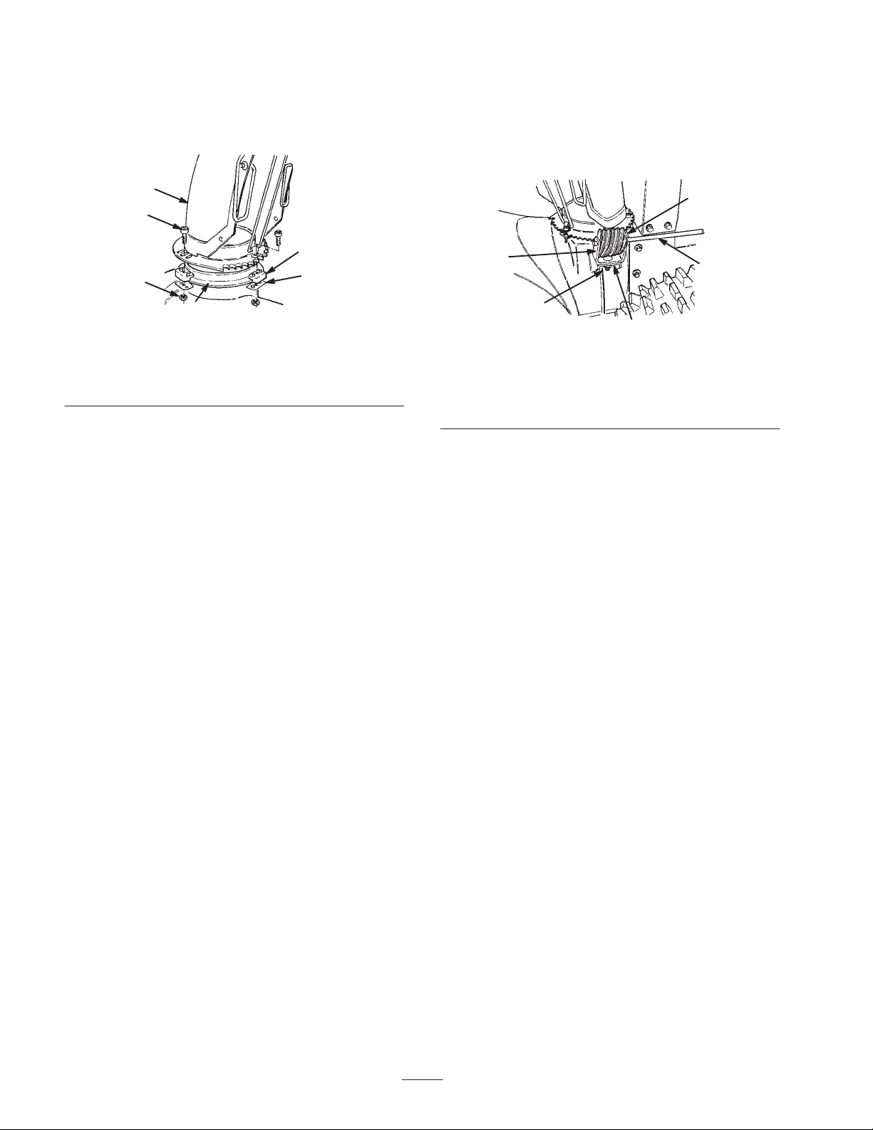
2. Remove the worm gear, gear bracket, chute gear rod,
carriage bolt, flat washer, and locknut (Fig. 2).
5
3. Chisel the weld and the remaining chute ring from the
chute opening of the auger housing.
4. Grind the surface clean of excess weld and paint the
surface.
5. Slide the new chute ring onto the chute opening and
position it so that it is 1-1/4 inches (3.2 cm) from the
top of the chute opening (Fig. 3).
1-1/4 in. (3.2 cm)
1
Figure 3
1. Chute ring
6. Weld the chute ring to the chute with 4 fillet welds
(1/8-inch) that are 1 inch long and 90 degrees apart.
7. Grind or scrape any weld splatter or excess weld from
the chute ring to allow the chute and retainers to freely
rotate.
8. Paint the areas where you removed any paint.
1
2
Figure 2
1. Gear bracket
2. Carriage bolt, flat washer,
and locknut
W 2004 by The Toro Company
8111 Lyndale Avenue South
Bloomington, MN 55420-1196
3
3. Mounting flange
4. Chute gear rod
5. Worm gear
4
170
Original Instructions (EN)
Contact us at www.Toro.com
All Rights Reserved
Printed in the USA
Page 2
Installing the Discharge Chute
Installing the Chute Control
1. Apply a light coat of low-temperature grease to the
chute ring (Fig. 4).
1
5
2
6
4
3
m-168
Figure 4
1. Discharge chute
2. Chute retainer (3)
3. Chute retainer plate (3)
4. Chute ring
5. Screw (3)
6. Locknut (3)
2. Set the discharge chute (open side forward) onto the
discharge opening so that the chute retainers are on the
chute ring (Fig. 4).
Note: Ensure that the chute retainer guide pins are in
the holes in the chute gear.
3. Tighten the screw and the locknut on the left side to
position the chute retainer against the chute retainer
plate and to secure the discharge chute to the chute ring
(Fig. 4).
4. Push the other chute retainers toward the discharge
chute (slotted) and tighten the screws (Fig. 4).
5. Ensure that the chute rotates freely on the chute ring. If
the chute binds, move the right-hand retainer outward
(Fig. 4).
Worm Gear
1. Insert the 1-inch (2.5 centimeters) carriage bolt into the
mounting hole of the gear bracket (Fig. 2).
5
1
2
3
Figure 5
1. Gear bracket
2. Carriage bolt, flat washer,
and locknut
3. Mounting flange
4. Chute gear rod
5. Worm gear
2. Position the worm gear into the bracket, align the holes,
and insert the chute gear rod through the bracket and the
gear (Fig. 2).
3. Loosely mount the worm gear and the bracket to the
mounting flange with a carriage bolt, a flat washer, and
a locknut (Fig. 2).
4. Slide the worm gear into the teeth of the chute gear and
tighten the locknut.
5. Operate the chute control. If the chute control binds,
apply a light coat of grease to the worm gear and move
it slightly outward if it binds; move it slightly inward if
it is too loose.
4
170
2
 Loading...