

Page 1

Form No. 3353-512
4
Recyclerr Kit
48in TURBO FORCE or 7–Gauge Side Discharge Mower
Part No. 108–2209
Installation Instructions
Note: Determine the left and right sides of the machine from the normal operating position.
Note: This kit will fit two different types of mower decks. One type of mower deck is shown in Figure 2 and has one front
baffle. The second type of mower deck is shown in Figure 3 and has an Adjustable Flow Baffle.
Loose Parts
Note: Use the chart below to identify parts for assembly.
Step Description Qty. Use
1
2
3
5
No parts needed – Removing the existing blades
No parts needed –
No parts needed –
Left baffle
Right baffle
Tapping bolt, 3/8 x 1 inch
Flange Nut, 3/8 inch
Carriage bolt, 3/8 x 3/4 inch
Washer, 3/8 inch (for mower decks with
an Adjustable Flow Baffle only)
Flange Nut, 5/16 inch
Carriage Bolt, 5/16 x 3/4 inch
Mulching blades 3 Installing the mulching blades
1
1
7
10
3
1
1
1
Removing the existing baffles from a
7–Gauge mower deck
Removing the existing baffles with
Adjustable Flow Baffle
Installing the baffles
W 2005 by The Toro Company
8111 Lyndale Avenue South
Bloomington, MN 55420-1196
Contact us at www.Toro.com
All Rights Reserved
1
Printed in the USA
Page 2
Side Discharge or Mulch Grass
Warning
Step
Without the grass deflector, discharge cover, or
complete grass catcher assembly mounted in place,
you and others are exposed to blade contact and
thrown debris. Contact with rotating mower
blade(s) and thrown debris will cause injury or
death.
• Never remove the grass deflector from the
mower because the grass deflector routes
material down toward the turf. If the grass
deflector is ever damaged, replace it
immediately.
• Never put your hands or feet under the mower.
• Never try to clear discharge area or mower
blades unless you move the power take off
(PTO) to disengage and turn the ignition key to
off. Also remove the key and pull the wire off
the spark plug(s).
Ensure the mower has the hinged grass deflector that
disperses clippings to the side and down toward the turf,
while in side discharge mode.
To mulch grass clippings, the baffles must be installed into
the mower as shown in the following steps.
1
Removing the Existing Blades
Parts needed for this step:
None
Procedure
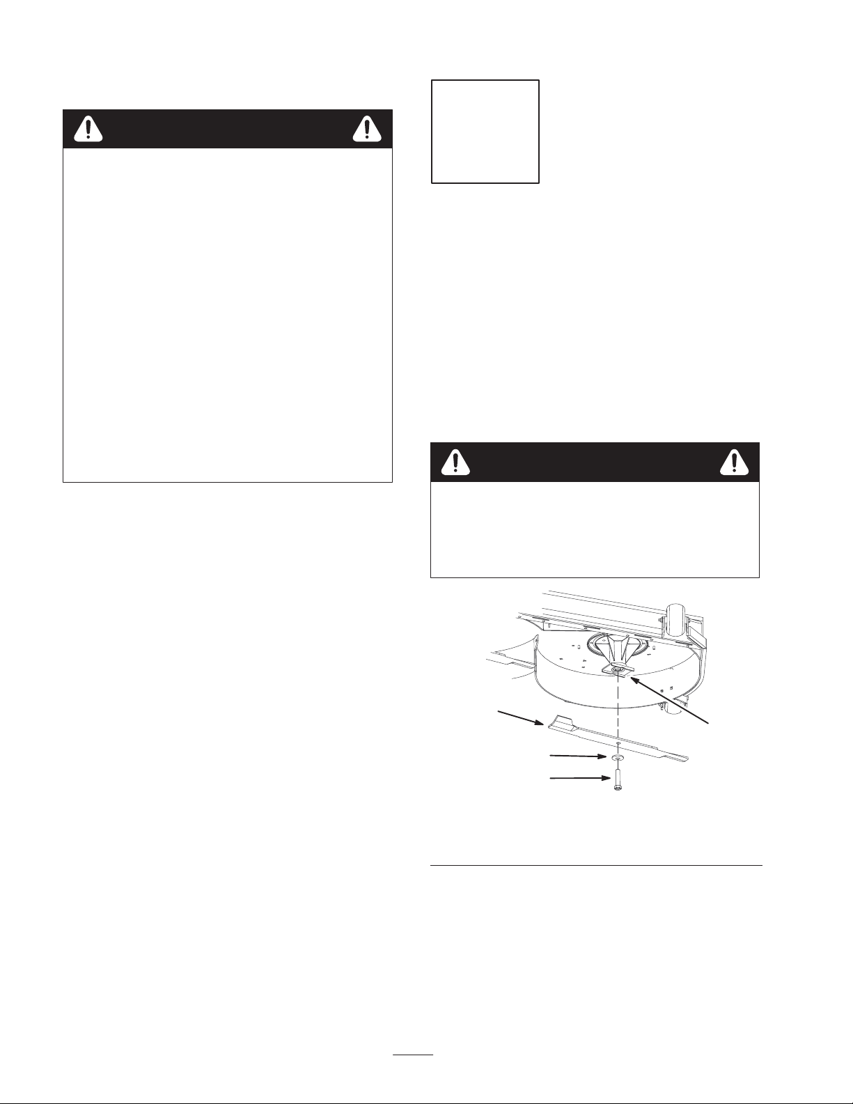
1. Remove the existing blades from the spindles (Fig. 1).
Note: Save the blades for use when in side discharging
mode. Use the blade bolt and washer for installing the
recycler blades in Step 4.
Warning
A blade is sharp. Contact with sharp blade can
cause serious personal injury.
• Wear gloves or wrap sharp edges of the blade
with a rag.
Before Installation
1. Thoroughly clean mower deck. All debris must be
removed to ensure baffles will fit properly against
mower deck.
2. Repair all bent or damaged areas of mower deck and
replace any missing parts.
1. Spindle
2. Blade
2
1
3
4
Figure 1
3. Washer
4. Blade bolt
m–6955
2
Page 3
Step
2
Removing the Existing Baffles
Removing the Existing Baffles with an
Adjustable Flow Baffle
Note: In the steps below, the bolts are threaded into the
mower deck. Remove the nuts first before removing bolts.
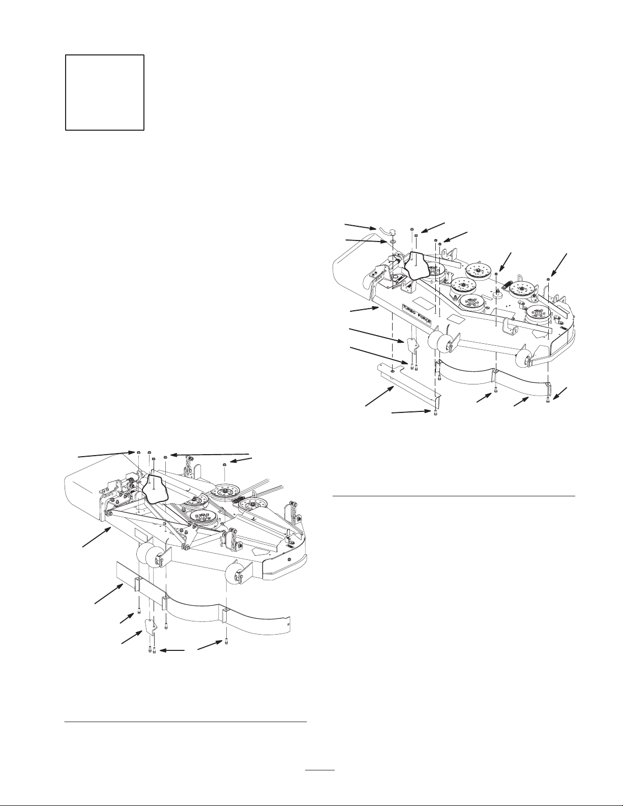
1. Remove the nuts holding the baffles in place (Fig. 3).
2. Remove the cam lock holding the Adjustable Flow
Baffle in place (Fig. 3).
3. Remove the bolts holding the baffles in place (Fig. 3).
Parts needed for this step:
None
Removing the Existing Baffles from a
7–Gauge Mower Deck
Note: The bolts are threaded into the mower deck. Remove
the nuts first before removing bolts.
1. Remove the nuts holding the front baffle in place
(Fig. 2).
2. Remove the nuts holding the discharge baffle in place
(Fig. 2).
3. Remove the bolts holding the front baffle in place
(Fig. 2).
4. Remove the bolts holding the discharge baffle in place
(Fig. 2).
Note: Save the baffle and hardware for use when changing
to side discharging mode.
4
4
Note: Save the baffles and hardware for use when changing
to side discharging mode.
5
6
7
8
3
1
3
1. Adjustable Flow Baffle
2. Left front baffle
3. Bolt
4. Lock Nut
4
Figure 3
4
4
3
5. Cam lock
6. Washer
7. Turbo Force mower deck
8. Discarge baffle
2
m–8144
4
3
3
1
2
m–8139
1. Front Baffle
2. Bolt
3. 7–gauge mower deck
5
2
Figure 2
4. Lock Nut
5. Discharge baffle
3
Page 4

Step
3
Installing the Baffles
Parts needed for this step:
Qty. Part
1 Left baffle
1 Right baffle
7 Tapping bolt, 3/8 x 1 inch
10 Flange nut, 3/8 inch
3 Carriage bolt, 3/8 x 3/4 inch
1 Washer, 3/8 inch (for mower decks with
Adjustable Flow Baffle only)
1 Flange nut, 5/16 inch
1 Carriage bolt, 5/16 x 1 inch
Procedure
Note: All holes exist in the mower for installing the new
baffles.
Note: Loosely install the baffles to align the baffles with all
existing holes in the mower. Tighten the tapping bolts into
the mower first, before tightening the flange nuts.
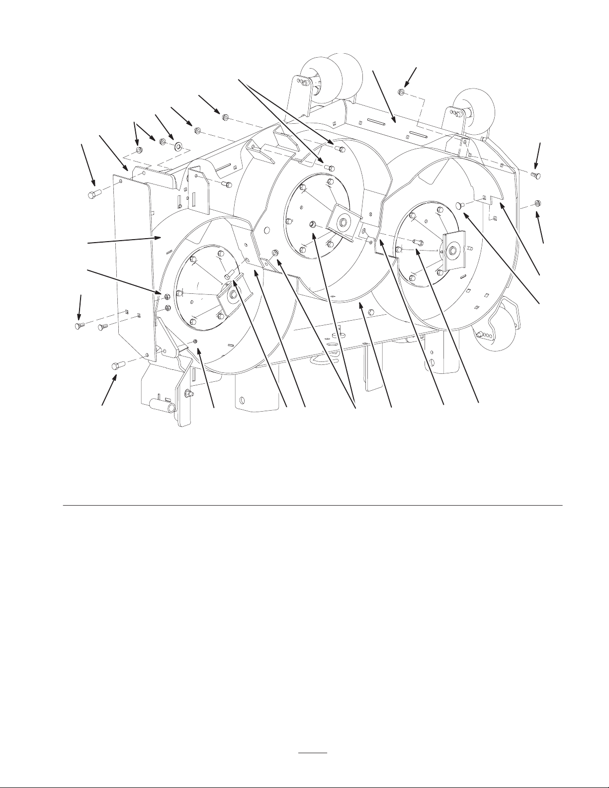
1. Install the right baffle into the mower.
Note: The tabs on the baffle for the center chamber need to
be installed to the outside.
2. Secure the right baffle to the mower deck with
2 tapping bolts (3/8 x 1 inch), 1 washer (3/8 inch, only
for Turbo Force mower decks), and 2 flange nuts
(3/8 inch) (Fig. 4).
3. Secure the right baffle to the rear baffle with 1 bolt
(3/8 x 1 inch) and 1 flange nut (3/8 inch) (Fig. 4).
4. Secure the right baffle to the mounting plate with
2 bolts (3/8 x 1 inch) and 2 flange nuts (3/8 inch)
(Fig. 4).
5. Install the left baffle into the mower.
6. Secure the left baffle to the mower deck with 1 tapping
bolt (3/8 x 1 inch) and 1 flange nut (3/8 inch) (Fig. 4).
7. Secure the left baffle to the front flat plate of the mower
with 1 carriage bolt (5/16 x 1 inch) and 1 flange nut
(5/16 inch) (Fig. 4).
8. Secure the left baffle to the left sidewall of the mower
deck with 1 carriage bolt (3/8 x 3/4 inch) and 1 flange
nut (3/8 inch) (Fig. 4).
9. Secure the left baffle to the rear baffle with 1 bolt (3/8 x
1 inch) and 1 flange nut (3/8 inch) (Fig. 4).
4
Page 5
3
13
5
6
6
8
6
11
5
4
1
6
9
5
1. Right front baffle
2. Left front baffle
3. Front flat plate
4. Carriage bolt, 5/16 x 3/4 inch
6
5. Tapping bolt, 3/8 x 1 inch
6. Flange nut, 3/8 inch
7. Rear baffle
5
12
Figure 4
6
8. Washer, 3/8 inch (for use on
mower decks with an
Adjustable Flow Baffle only)
9. Carriage bolt, 3/8 x 3/4 inch
7
12
10. Bolt, 3/8 x 1 inch
11. Mounting plate
12. Tab to the outside
13. Flange nut, 5/16 inch
5
6
2
9
m–7826
5
Page 6
Step
4
Installing the New Blades
lush and dense grass you may need to raise the
height-of-cut setting or convert to side discharge or bagging
operations.
Mowing in extreme conditions – Air is required to cut and
recut grass clippings in mower housing, so do not set
height–of–cut too low or totally surround housing by uncut
grass. Always try to have one side of the mower housing
free from uncut grass, allowing air to be drawn into
housing. When making an initial cut thru center of uncut
area, operate machine slower and back up if mower starts to
clog.
Parts needed for this step:
Qty. Part
3 Mulching blades
Procedure
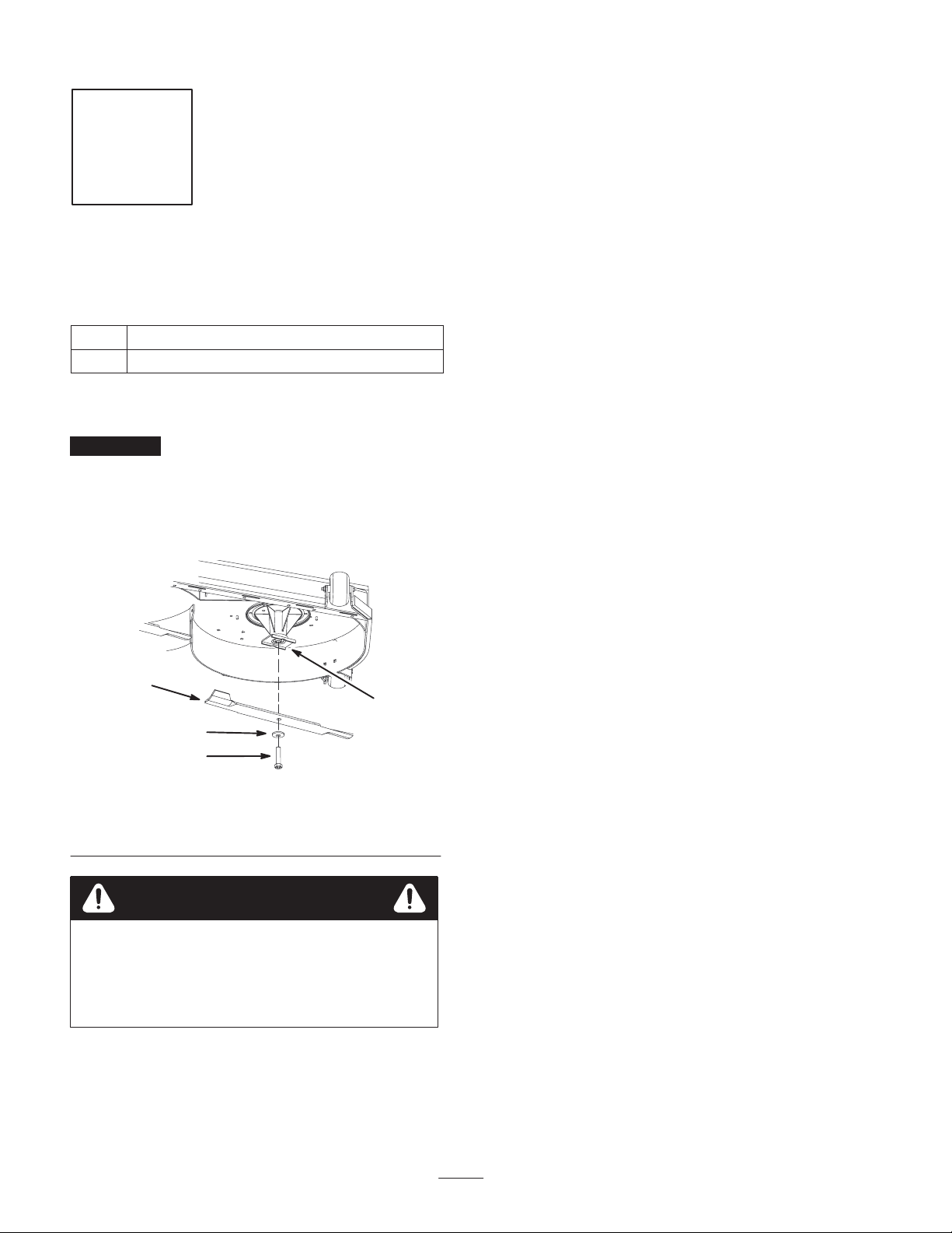
Important The sail part of the blade (i.e., the turned up
section) must face the inside of the mower (Fig. 5).
1. Install the new blades to the spindles with washers and
blade bolts that were previously removed (Fig. 5).
2. Tighten the blade bolt to 85–110 ft-lb (115–150 N⋅m).
2
1
3
Mow at proper intervals – Under most normal conditions
you’ll need to mow every 4–5 days. However, grass grows
at different rates at different times. Thus, in order to
maintain the same height-of-cut, which is a good practice,
you’ll need to cut more frequently in early spring; as the
grass growth rate slows in mid summer, cut only every
8–10 days. If you are unable to mow for an extended period
due to weather conditions or other reasons, convert to side
discharge or bagging options or mow first with the
height-of-cut at a high level; then mow again 2–3 days later
with a lower height setting.
Always mow with sharp blades – A sharp blade cuts
cleanly and without tearing or shredding the grass. A dull
blade will tear and shred the grass. Tearing and shredding
causes the grass to turn brown at the edges which impairs
growth and increases susceptibility to disease.
After operating – To ensure optimum performance, clean
underside of mower housing after each use. If residue is
allowed to build up in mower housing cutting performance
will decrease.
1. Spindle
2. Blade
4
Figure 5
3. Washer
4. Blade bolt
m–6955
Warning
A blade is sharp. Contact with sharp blade can
cause serious personal injury.
• Wear gloves or wrap sharp edges of the blade
with a rag.
Mulching Tips
Selecting the proper height-of-cut setting to suit
conditions – Remove approximately one inch or no more
than 1/3 of the grass blade when cutting. In exceptionally
6
Page 7

7
Page 8

8
 Loading...