

Toro 108-2162 Installation Instructions
Roller Striping Kit
For Z Master® TURBO FORCE® Mowers
Model No. 108-2162
Safety
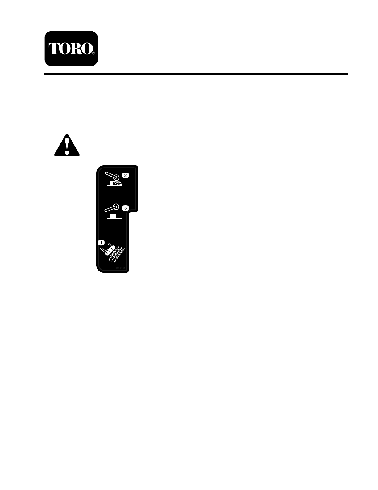
Safety and Instructional Decals
Safety decals and instr uctions are easily visible to the operator and are located near any
area of potential dang er . R e place any decal that is damag ed or lost.
Form No. 3355-906 Rev A
Installation Instructions
108-4108
1. Striping roller 3. Raise the striping roller.
2. Engage the striping roller.
© 2006—The Toro® Company
8111 Lyndale Avenue South
Bloomington, MN 55420
Register at www.Toro.com. Original Instructions (EN)
Printed in the USA.
All Rights Reserved
Installation
Loose Parts
Use the chart below to verify that all parts have been shipped.
Step
Flange bushing
Roller assembly
Bolt (3/8 x 4-3/4 inches)
Washer
1
2
Spacer 2
Right-hand spring
Left-hand spring
Locknut (3/8 inch)
Control lever assembly
Bolt (7/16 x 2 inches)
Flange nut (7/16 inch)
Locknut (3/8 inch)
Description
Note: Deter mine the left and right sides of the
mac hine from the nor mal operating position.
Step
1
Qty.
2
1
2
2
1
1
2
1
1
2
2
Install the roller.
Install the control lever assembly.
Use
Installing the Roller
Parts needed for this step:
2
Flange bushing
1
Roller assembly
2
Bolt (3/8 x 4-3/4 inches)
2
Washer
2 Spacer
1
Right-hand spring
1
Left-hand spring
2
Locknut (3/8 inch)
Procedure
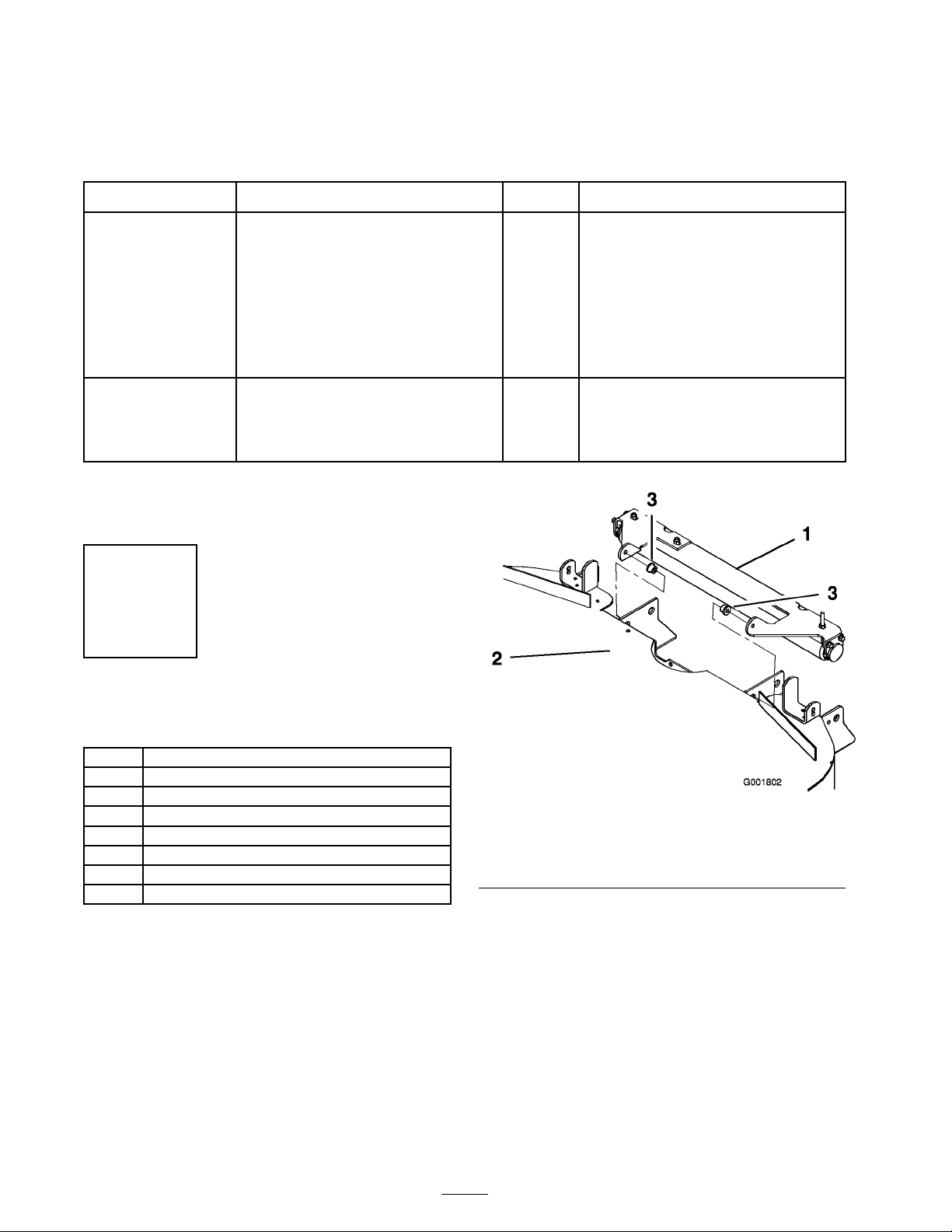
1. Inser t a flang e bushing into the front hole of
eac h brac k et on the bac k of the mo w er ( Figure
1 ).
Figure 1
1. Roller assembly 3. Flange bushing
2. Rear of the mower deck
(viewed from the front)
2. T hread a w asher , spacer , and spring (with the
long end to w ard the bolt head) onto eac h bolt
(3/8 x 4-3/4 inc hes) ( Figure 2 )
2
 Loading...