

Page 1

Roll Over Protection System Kit
400 Series Z Masters
Part No. 107–8093
Note: This kit is used for replacing an existing ROPS.
Loose Parts
Note: Use the chart below to identify parts for assembly.
Step Description Qty. Use
Form No. 3353–236
Installation Instructions
1
2
3
4
5
6
No parts needed – Removing the existing seat
Seat frame 1 Installing the new seat frame
Seat latch catch
Bolt, 5/16 x 7/8 inch
Locknut, 5/16 inch
Seat belt
Bolt, 7/16 x 1 inch
Locknut, 7/16 inch
Roll bar, right section
Roll bar, left section
Roll bar, center section
Bolt, 3/8 x 1 inch
Curved washer, 3/8 inch
Flange nut, 3/8 inch
Bolt, 1/2 x 3-1/4 inches
Flange nut, 1/2 inch
Lanyard
No parts needed – Checking the tire pressure
1
2
2
1
2
2
1
1
1
8
8
8
2
2
2
Installing the new seat latch catch
Installing the seat belt
Installing the roll over protection system
(ROPS)
2005—The Toro Company
8111 Lyndale Ave., Blomington, MN 55420, USA
Printed in the USA
All Rights Reserved
Register your product at www.Toro.com
Original Instructions (EN)
Page 2
2
Step
1
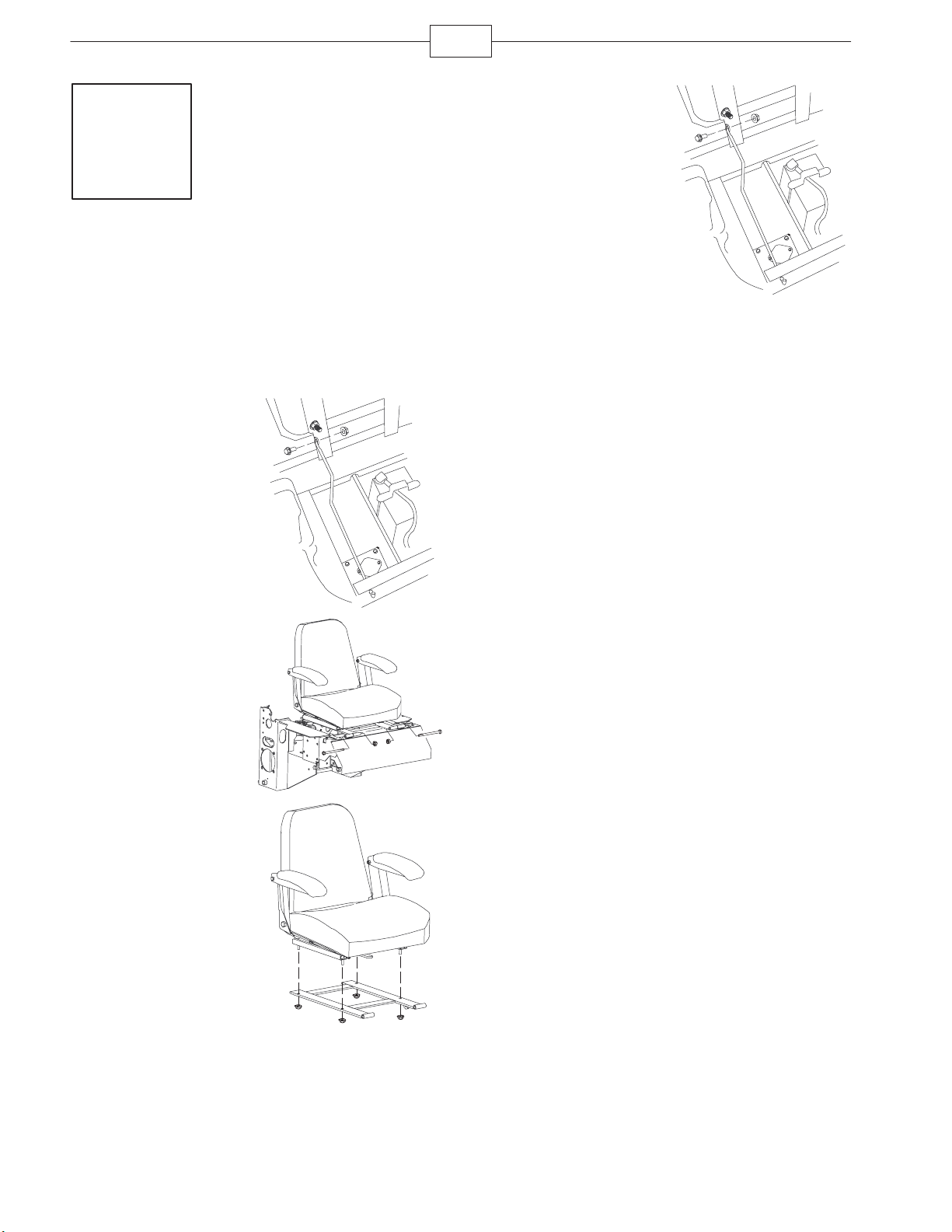
Removing the Existing Seat
Frame
Parts needed for this step:
None
Procedure
1. Remove the nut and
bolt from the seat
retaining rod.
5. Install the seat
retaining rod with the nut
and bolt previously
removed.
m–7036
2. Remove the 2 bolts
and 2 locknuts at the
front of the seat where it
is hinged. Save the
hardware.
3. Remove the seat
assembly from the
machine.
4. Remove the seat
frame from the existing
seat by removing the
four locknuts. Discard
the seat frame.
m–7036
m–7021
m–7023
Page 3
3
Step
2
Installing the New Seat
Frame
Parts needed for this step:
Qty. Part
1 Seat frame
Procedure
1. Install the seat to
the new seat frame with
the four locknuts
previously removed.
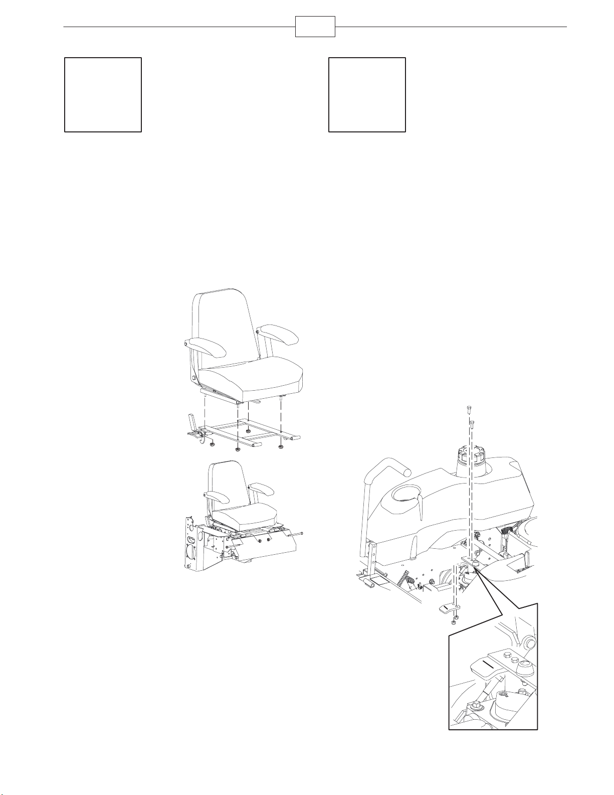
Step
3
Installing the Seat Latch
Catch
Parts needed for this step:
Qty. Part
1 Seat latch catch
2 Bolt, 5/16 x 7/8 inches
2 Locknut, 5/16 inch
m–7022
Procedure
1. Remove the existing seat latch from the machine.
2. Install the new seat latch catch under the frame
with 2 bolts (5/16 x 7/8 inch) and 2 locknuts
(5/16 inch).
Note: The bent part of the latch catch should point
downward.
2. Install the seat at
the hinges with the 2
bolts and 2 locknuts
previously removed.
m–7029
m–8224
Page 4

4
Step
4
Installing the Seat Belt
Parts needed for this step:
Qty. Part
2 Seat belt
2 Bolt, 7/16 x 1 inch
2 Locknut, 7/16 inch
Procedure
1. Install the receiver
part of the seat belt
between the cushion
and the metal seat
frame with 1 bolt (7/16 x
1 inch) and 1 locknut
(7/16 inch).
Step
5
Installing the Roll Over
Protection System (ROPS)
Parts needed for this step:
Qty. Part
1 Roll bar, right section
1 Roll bar, left section
1 Roll bar, center section
8 Bolt, 3/8 x 1 inch
8 Curved washer
8 Flange nut, 3/8 inch
2 Bolt, 1/2 x 3-1/4 inches
2 Flange nut, 1/2 inch
2 Lanyard
2. Install the long seat
belt strap between the
cushion and the metal
seat frame with 1 bolt
(7/16 x 1 inch) and
1 locknut (7/16 inch).
m–7024
Procedure
1. Loosely install the right and left roll bar sections
to the frame, using 8 bolts (3/8 x 1 inch), 8 curved
washers, and 8 flange nuts (3/8 inch).
m–7025
Page 5

5
5. Raise the roll bar
into the upright position
and secure it with the
pins and hairpin cotter
pins fastened to the
lanyards.
6. Torque all the lower
fasteners that are
attached to the machine
frame to 30 ft-lb.
7. Tighten the center
roll bar bolts
(1/2 x 3-1/4 inches) so
that the roll bar rotates
freely with some
resistance.
Note: Make sure that no
more than one thread is
exposed outside the nut.
m-7431
m-7432
2. Install the lanyard
clips onto the 2 bolts
(1/2 x 3-1/4 inches).
Note: Make sure the
bent tab points toward
the head of the bolt.
3. Lightly oil the ends
of the center roll bar
section.
4. Loosely install the
center roll bar section,
using 2 bolts
(1/2 x 3-1/4 inches) and
2 flange nuts (1/2 inch).
Note: Make sure the
bolts are installed on the
outside of the roll bar.
Note: Make sure the
lanyard tab is installed
as shown and points
forward.
m-7410
m-6916
m-7432
8. Tighten the front
handles against the
center roll bar ends.
m-7406
Page 6

Step
6
Checking the Tire Pressure
Parts Needed for This Step
None
Procedure
Check the air pressure
in the front and rear tires
and make sure that they
are set to 13 psi
(90 kPa).
6
m-6873
Page 7

7
Page 8

8
 Loading...