

Page 1

Conversion Kit
Z200 to Z500 DFS Bagger
Part No. 107–7650
Loose Parts
Note: Use the chart below to identify parts for assembly.
Step Description Qty. Use
Form No. 3351–335
Installation Instructions
1
2
3
4
5
6
7
No parts needed – Removing the bagger arm
Stop plate 1 Installing the stop plate
Bagger arm 1 Installing the bagger arm
Foam grip 2 Installing the latch lever
Cable
Long clevis, liquid cooled machines only
Short clevis
Clevis pin
Cotter pin
No parts needed – Adjusting the bagger arm
Pulley
Plate
Bearing housing
Key
Bolt, 3/8 x 5/8 inch
Spring washer, 3/8 inch
1
1
1
1
1
2
1
1
2
2
2
Installing the new cable
Installing the drive pulley assembly
Tensioner bracket template
8
9
10
11
2004 by The Toro Company
8111 Lyndale Avenue South
Bloomington, MN 55420-1196
Eyebolt template
Tensioner bracket 1
No parts needed –
No parts needed – Adjusting the bagger belt
1
1
1
Drilling holes for the idler bracket and
the eyebolt
Installing the tensioner bracket and the
eyebolt
Installing the bagger tensioner
assembly and the belt
Contact us at www.Toro.com
All Rights Reserved
Printed in the USA
Page 2
Step UseQty.Description
12
13
14
15
16
Step
No parts needed – Installing and adjusting the mower belt
Middle tube 1
Mounting plate 1
Boot
Middle tube
Flexible tube
Clamp
Weight
U–Bolt, 3/8 X 6 inch
Lock nut, 3/8 inch
Washer, 3/8 inch
Spacer
1
1
1
1
1
2
4
4
4
Installing hardware onto a new middle
tube
Installing the existing boot and brackets
to the new mounting plate
Installing the boot and discharge tubes
Installing the weight
5
2
4
7
8
1
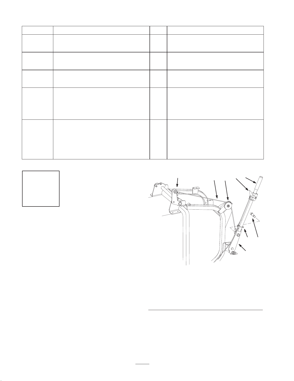
Removing the Existing Bagger
Arm
Parts needed for this step:
None
Procedure
1. Remove the shoulder bolt and cable from the bagger
arm (Fig. 1).
2. Loosen the nut and pulley on the bagger and remove the
cable from the pulley (Fig. 1).
3. Remove the cable from the bagger door hinge (Fig. 1).
Save all the hardware.
1
m–6136
Figure 1
1. Bagger arm
2. Cable
3. Shoulder bolt
4. Pulley and nut
4. Loosen the setscrew holding the latch lever (Fig. 6).
5. Remove the plastic cable ties on the handle and slide
the latch lever down the handle (Fig. 1).
5. Bagger door hinge
6. Cable tie
7. Latch lever
8. Grip
36
6. Remove the grip from the bagger arm (Fig. 3).
2
Page 3
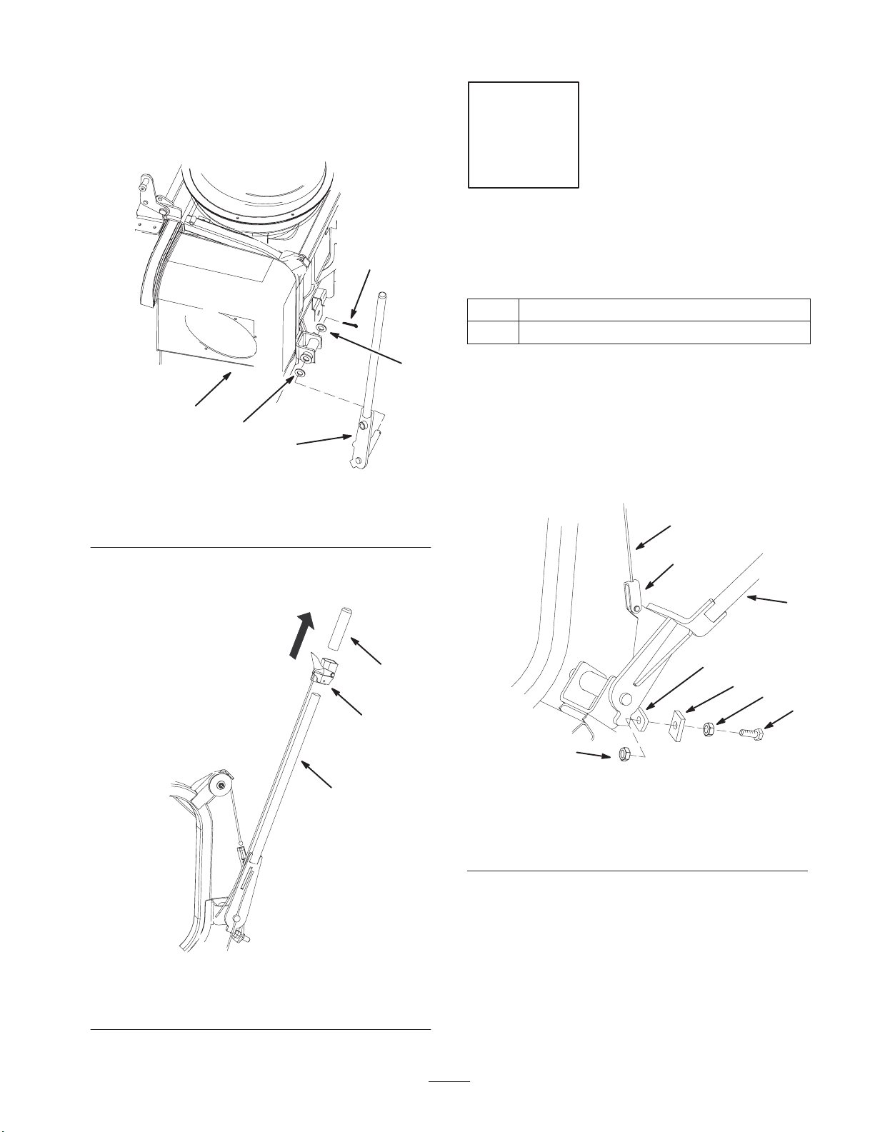
7. Remove the cotter pin and washer from the bagger arm
(Fig. 2). Save the washer and cotter pin.
8. Slide the bagger arm and washer out from the bagger
frame (Fig. 2). Save the washer.
3
Step
2
Installing the Stop Plate
Parts needed for this step:
Qty. Part
1
Stop plate
2
m–6206
1. Bagger arm
2. Bagger
9. Remove the latch lever off of the bagger arm and
discard the the bagger arm (Fig. 3).
4
1
Figure 2
3. Cotter pin
4. Washer
2
1
4
Procedure
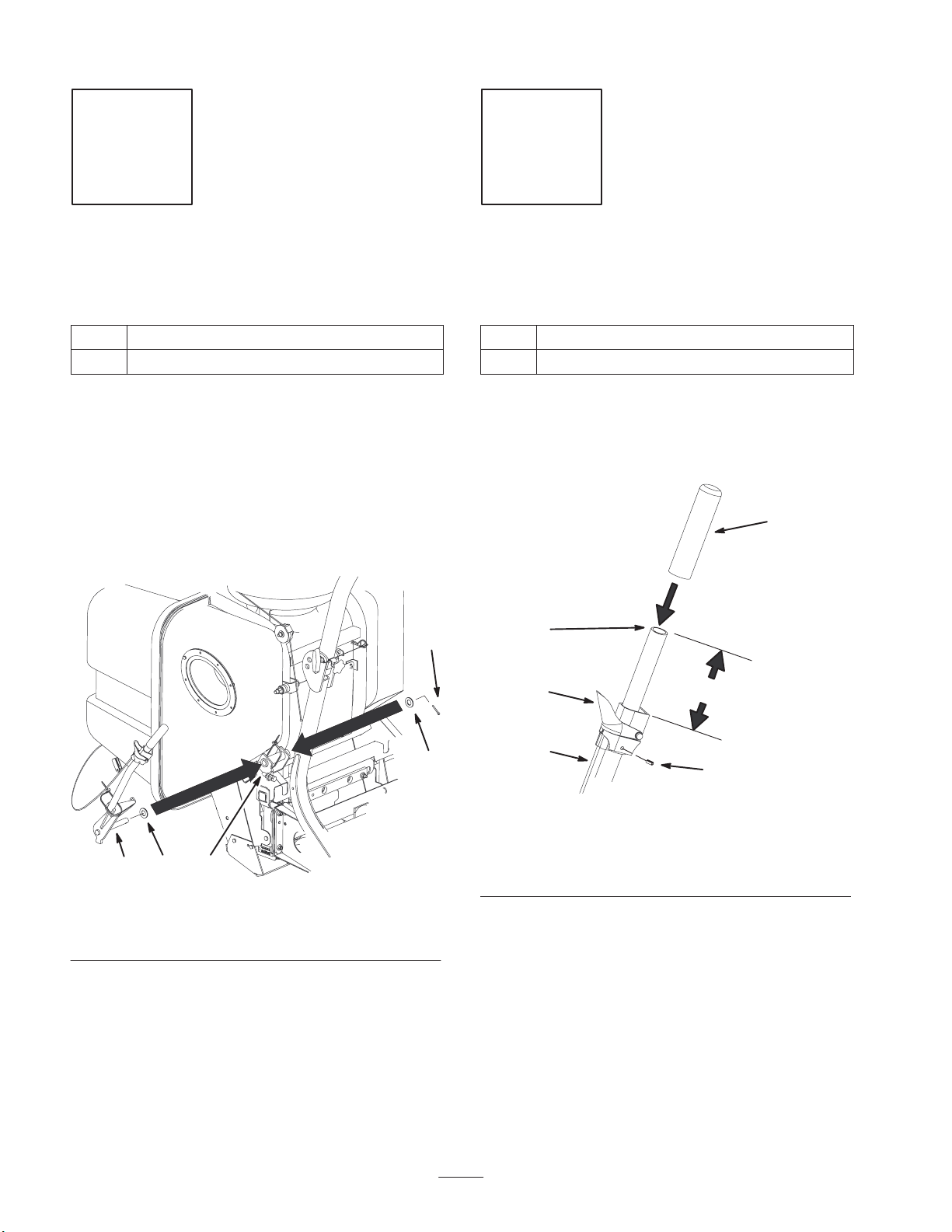
1. Remove the existing stop bolt and jam nuts from the
bagger frame (Fig. 4).
2. Install the stop plate to the stop bracket using the bolt
and jam nut previously removed (Fig. 4). Do not
tighten.
2
3
1
3
5
Figure 4
1. Bagger dump lever
2. Bagger cable
3. Bagger cable clevis
4. Bolt, 1/2 x 1–3/4 inch
5. Jam nut, 1/2 inch
6. Stop bracket
7. Stop plate
6
7
5
4
m–7513
1. Bagger Arm
2. Latch lever
m–7173
Figure 3
3. Foam grip
3
Page 4
Step
Step
3
Installing the Bagger Arm
Parts needed for this step:
Qty. Part
1
Bagger arm
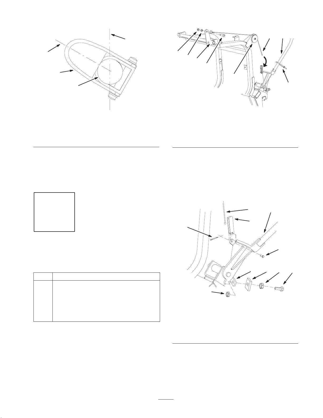
Procedure
1. Install the latch lever onto the bagger arm.
2. Install 1 washer previously removed onto the bagger
arm pivot and install the bagger dump handle into the
bagger frame (Fig. 5).
3. Secure the bagger handle with the previously removed
washer and cotter pin (Fig. 5).
4
Installing the Latch Lever
Parts needed for this step:
Qty. Part
1
Foam grip
Procedure
1. Position the latch lever 6 inches (15.2 cm) down from
the end of the bagger arm. See Figure 6.
5
214
1. Bagger arm pivot
2. Washer
Figure 5
3. Cotter pin
4. Bagger frame
m–7515
3
2
1. Bagger arm end
2. Latch lever position
3. Latch lever cable
2. Position the latch lever at the 10 o’clock position when
1
2
3
Figure 6
looking at the end of the handle (Fig. 7).
6
4
4. Set screw
5. Foam grip
6. 6 inches (15.2 cm)
m–7175
4
Page 5
2
1
4
3
1
2
m–7176
Figure 7
End view of handle
1. Latch lever
2. End of handle
3. 10 o’clock position
4. 12 o’clock position
3. Tighten the setscrew that holds the latch lever (Fig. 6).
4. Install the cable ties (Fig. 9).
5. Install the foam grip onto the bagger arm (Fig. 6).
Step
7
8
5
3
4
m–7178
Figure 8
1. Bagger arm
2. Cable
3. Shoulder bolt
4. Pulley and nut
5. Bagger door hinge
6. Cable tie
7. Nut
8. Washer
Note: Install the long cable clevis onto the bagger dump
handle if it is for a liquid cooled machine (Fig. 9).
3. Secure the bagger cable clevis to the bagger arm with
the clevis pin and cotter pin (Fig. 9).
4. Install the cable into the cable clevis installed on the
bagger handle (Fig. 9).
6
5
Installing the New Cable
Parts needed for this step:
Qty. Part
1
Cable
1 Long clevis, liquid cooled machines only
1 Short clevis
1 Clevis pin
1 Cotter pin
Procedure
1. Install the new cable to the top of the bagger with the
previously removed shoulder bolt, washer and nut
(Fig. 8).
2. Install the cable into the pulley and tighten the nut
(Fig. 8).
2
1
3
8
7
6
9
5 4
m–7520
5
Figure 9
1. Bagger dump lever
2. Bagger cable
3. Long cable clevis—liquid
cooled machines only
4. Bolt, 1/2 x 1–3/4 inch
5. Jam nut, 1/2 inch
6. Stop bracket
7. Clevis pin
8. Cotter pin
9. Stop plate
5. Adjust the handle stop, refer to Adjusting the Bagger
Arm, page 6.
5
Page 6

Step
Step
6
Adjusting the Bagger Arm
Parts needed for this step:
None
Procedure
The bagger arm needs to be adjusted to remove slack in the
bagger cable with the bagger door closed.
1. Loosen the nuts on both sides of the stop bracket
(Fig. 10).
2. Adjust the stop bolt until there is no slack in the bagger
cable (Fig. 10).
3. Tighten the nuts on both sides of the stop bracket
(Fig. 10).
1
7
Installing the Drive Pulley
Assembly
Parts needed for this step:
Qty. Part
2 Pulley
1 Plate
1 Bearing housing
2 Bolt, 3/8 x 5/8 inch
2 Spring washer, 3/8 inch
2 Key
Procedure
1. Remove the existing drive belts from the machine
(Fig. 21).
m–7514
1. Bagger dump lever
2. Stop bracket
3. Stop bolt
2. Remove the existing drive pulley assembly from the
machine (Fig. 11).
1 5 2645
3
Figure 10
4. Bagger cable
5. Nut
6. Stop plate
6
Page 7

5
1
7
8
9
7
6
9
8
10
2
4
2
1
7
5
6
3
m–6001
Figure 11
1. Rear frame
2. Drive pulley assembly
3. Bolt, 1/2 x 1–1/4 inch
4. Nut, 1/2 inch
5. Washer, 1/2 inch
6. Cut–out
7. Pulley plate
3. Remove the pulleys from the existing assembly.
4. Remove the plate from the existing bearing housing.
5. Install the new bearing housing and existing spacers to
the new plate (Fig. 12).
Note: Install the new small pulley nearest the cutout in the
plate (Fig. 12).
6. Install the new pulleys to the bearing housing with 2
bolts (3/8 x 5/8 inch), 2 spring washer (3/8 inch) and 2
keys (Fig. 12).
3
11
4
m–7495
Figure 12
1. New small pulley
2. New bearing housing
3. New plate
4. Bolt
5. Nut
6. Spacer
7. Bolt, 3/8 x 5/8 inch
8. Spring washer, 3/8 inch
9. Key
10. New large pulley
11. Cut–out
7. Install the mower belt onto the drive pulley assembly
(Figures 13 and 21).
Note: Make sure the cut–out in the pulley plate is on the
left–hand side of the machine (Fig. 11). This cut–out allows
room for the mower spring loaded idler pulley.
8. Install the pulley assembly under the rear frame, and
loosely install 4 bolts (1/2 x 1–1/4 inch), 4 washers
(1/2 in.) and 4 locknuts (1/2 inch) (Fig. 11). Do not
tighten bolts now.
Positioning the Drive Pulley Assembly on
an Air Cooled Machine
1. Push the drive pulley assembly all the way forward and
then rearward a 1/4 inch (6 mm) (Fig. 11).
Note: The bolt head on the drive pulley assembly, should
be approximately centered horizontally, in the frame slot
(Fig. 13). View this from the right–hand side of the
machine.
2. Tighten the 4 bolts (1/2 x 1–1/4 inch), 4 washers
(1/2 in.) and 4 locknuts (1/2 inch) (Fig. 11).
7
Page 8

Important A final adjustment may be needed when
installing the bagger belt.
Positioning the Drive Pulley Assembly on
a Liquid Cooled Machine
1. Pull the drive pulley assembly all the way rearward and
then forward a 1/4 inch (6 mm) (Fig. 11).
Step
8
Note: The bolt head on the drive pulley assembly, should
be approximately a 1/4 inch (6mm) rearward of the center
in the frame slot (Fig. 13). View this from the right–hand
side of the machine.
3
1
4
6
Figure 13
1. Drive pulley assembly
2. Bolt head—air cooled
machine only
3. Mower drive belt
2. Tighten the 4 bolts (1/2 x 1–1/4 inch), 4 washers
(1/2 in.) and 4 locknuts (1/2 inch) (Fig. 11).
Important A final adjustment may be needed when
installing the bagger belt.
4. Bolt head—liquid cooled
machine only
5. Frame slot
6. 1/4 inch—liquid cooled
5
2
m–5861
Drilling Holes for the Tensioner
Bracket and Eyebolt
Parts needed for this step:
Qty. Part
1
Tensioner bracket template
1 Eyebolt template
Procedure
1. Remove the four bolts in the skid plate (Fig. 14).
2. Remove the skid plate (Fig. 14). This will make it easier
to remove and install the hardware and belts.
1
2
m–6984
1. Bolts
2. Skid plate
4
Figure 14
3
3. Bagger tensioner
assembly
4. Existing tensioner bracket
3. Remove the existing bagger tensioner assembly from
the tensioner bracket (Fig. 14). Save the hardware.
4. Remove the existing tensioner bracket and eyebolt from
the bagger frame. Save the hardware.
5. Place the tensioner bracket template flush against the
wall and bottom of the bagger bracket and tight against
the side of the bagger bracket (Fig. 15).
8
Page 9

6. Align the eyebolt template with the existing hole in the
bagger frame (Fig. 15).
Note: Make sure the templates are tight against the bagger
frame (Fig. 15).
3
5
1
4
5
1
2
m–7491
Figure 15
1. Tensioner bracket
template
2. Eyebolt template
3. Bagger frame
4. Correct template position
5. Bagger wall
7. Using the templates, mark and center punch the holes.
8. Drill three 1/8 inch pilot holes into the frame (Fig. 16).
9. Remove the templates and discard them.
4
2
1. 9/32 inch hole to drill
2. 11/32 inch holes to drill
3. Bagger frame
2
3
1
m–7492
Figure 16
4. Tensioner bracket
template
5. Eyebolt template
10.Drill 2 holes, 11/32 inch diameter, into the 1/8 inch pilot
holes from the tensioner bracket template (Fig. 16).
11. Drill 1 hole, 9/32 inch diameter, into the 1/8 inch pilot
holes from the eyebolt template (Fig. 16).
9
Page 10

Step
Step
9
Installing the Tensioner
Bracket and Eyebolt
Parts needed for this step:
Qty. Part
1
Tensioner bracket
Procedure
1. Install the tensioner bracket to the bagger frame with
the previously removed nuts (Fig. 14).
2. Install the previously removed eyebolt with the
previously removed nuts (Fig. 14).
5
10
Installing the Bagger Tensioner
Assembly and Belt
Parts needed for this step:
None
Procedure
1. Install the bagger tensioner assembly to the tensioner
bracket with with the previously removed bolt, washers
and lock nut (Fig. 18).
7
3
4
1
1. Bolt
2. Eyebolt
3. Nut
Figure 17
4. New tensioner bracket
5. Bagger frame
3
3
2
m–7493
1. Bagger tensioner bracket
2. Eyebolt
3. Lock nut
4. Bolt
2. Install the bagger belt onto the drive pulley
(Fig. 20 and 21).
3. Route the bagger belt onto the bagger pulley
(Figures 19 and 20).
10
1
5
6
Figure 18
5. Washer
6. Bagger tensioner
7. Bagger frame
2
5
4
m–7496
assembly
Page 11

3
2
1
1
5
5
1. Tensioner spring
2. Eye bolt
3. Bagger tensioner pulley
4. Bagger pulley
Note: There should be a 1/4 twist in the belt when it is
installed onto the bagger tensioner pulley
4. Install the spring onto the idler arm (Fig. 19).
5. Install the tensioner spring onto the eyebolt attached to
the bagger (Fig. 19 and 22).
6. Adjust the bagger belt for proper tension. Refer to
Adjusting the Bagger Belt on page 11.
7. Adjust the Mower belt tension. Refer to Adjusting the
Mower Belt Tension on page 12.
8. Install the skid plate (Fig. 14).
3
Figure 19
5. Belt
6. Shortest space between
m–5887
belt strands, 1 inch
±1/8 inch
4
6
2
Figure 21
1. Drive pulley assembly
2. Mower belt
3. Bagger belt
4. Mounting bolts
5. Back of machine
Step
11
Adjusting the Bagger Belt
Parts needed for this step:
None
4
m–5892
1. Drive pulley
2. Bagger tensioner pulley
1
Figure 20
3. Bagger pulley
4. 1/4 twist
Procedure
1. Check the belt tension (Fig 22).
2. Measure the gap at the bagger tensioner pulley, between
the tight and slack side of the belt when the bagger
tensioner pulley and spring are installed (Fig. 22).
3
2
4
m–5773
3. There must be a gap of 1 inch ± 1/8 inch (26mm ± 3
mm) between the belt strands (Fig 22).
4. If the gap is not correct, remove the tensioner spring
from the eyebolt to remove the tension on the PTO
spring loaded idler (Fig 22).
5. Loosen the 4 mounting bolts holding the drive pulley
assembly (Fig 21).
6. If the gap measurement is too small, push the pulley
assembly forward slightly [1/8–3/16 inch (3–5 mm)]
from the original set–up position (Fig 21).
11
Page 12

7. If the gap measurement is too large, pull the pulley
assembly rearward slightly [1/8–3/16 inch (3–5 mm)]
from the original set–up position (Fig 21).
8. Tighten the 4 mounting bolts holding the drive pulley
assembly to the machine frame (Fig 21).
9. Install the tensioner spring to the eyebolt to apply
tension on the PTO spring loaded idler.
Step
12
10.Measure the bagger belt spacing. There must be a gap
of 1 inch ± 1/8 inch (26mm ± 3 mm) between the belt
strands (Fig 22).
11. Repeat this procedure if a gap of 1 inch ± 1/8 inch
(26mm ± 3 mm) was not achieved (Fig 22).
2
1
4
6
5
1. Tensioner spring
2. Eye bolt
3. Bagger tensioner pulley
4. Bagger pulley
3
Figure 22
5. Belt
6. Shortest space between
m–5887
belt strands, 1 inch
±1/8 inch
Installing and Adjusting the
Mower Belt
Parts needed for this step:
None
Procedure
1. Disengage the PTO, move the motion control levers to
the neutral locked position and set the parking brake.
2. Stop the engine, remove the key, and wait for all
moving parts to stop before leaving the operating
position.
3. Raise the mower to the transport position.
4. Ensure the mower belt is installed on all mower pulleys
(Fig 23).
Important Check the amount of twist in the belt
between the pulleys. Make sure it is only what is specified
in Figure 23.
1
3
3
5
2
1. Clutch
2. Mower belt
3. 1/4 turn belt twist
Important Check and make sure the belt is installed
into both the front and rear belt guides (Fig 24).
5. Check the belt tension. The spring loaded idler center
bolt needs to be near the top alignment hole in the left
support plate (Fig 24).
12
3
4
6
Figure 23
4. Belt guide
5. Mower spindle pulley
6. Mower idler pulley
4
3
m–6825
Page 13

Step
1
2
3
1
Figure 24
1. Center bolt
2. Alignment hole
6. If adjustment is required, loosen the mower idler plate
to adjust it (Fig. 25).
7. Insert a ratchet or breaker bar into the square hole in the
mower idler plate to adjust the tension (Fig. 25).
8. To increase belt tension, rotate the mower idler plate
until resistance is felt and rotation stops. Do not go past
when it stops (Fig. 25).
9. Tighten the idler plate bolts (Fig. 25).
3. Left support plate
4. Spring loaded idler
3
4
M–4417
13
Installing Hardware onto the
New Middle Tube
Parts needed for this step:
Qty. Part
1
Middle tube
Procedure
1. Remove the rubber latch, mounting bracket and the
hardware from the existing middle tube.
2. Install the rubber latch, mounting bracket to the new
middle tube with the existing hardware (Fig. 26).
1
2
m–6826
1. Mower idler plate
2. Square hole
1
Figure 25
3. Ratchet or breaker bar
4. Idler plate bolt
4
2
1. Middle tube
2. Existing rubber latch
3
4
4
m–7497
Figure 26
3. Existing mounting bracket
4. Hardware
13
Page 14

Step
4. Install the boot to the new mounting plate with exiting
hardware (Fig. 28).
14
Installing the Existing Boot and
Brackets to the New Mounting
Plate
Parts needed for this step:
Qty. Part
1
Mounting plate
Procedure
1. Remove the existing mounting plate from the boot.
Save the hardware.
2. Remove the existing mounting bracket and bracket
clamp from the existing mounting plate. Save the
hardware.
4
1
1. Boot
2. New mounting plate
Step
15
3
2
m–7499
Figure 28
3. Existing bolt
4. Existing nut
3. Install the existing mounting bracket and bracket clamp
to the new mounting plate (Fig. 27).
4
3 4
4
2
m–7500
1. New mounting plate
2. Existing mounting
bracket
1
Figure 27
3. Existing bracket clamp
4. Existing hardware
Installing the Boot and
Discharge Tubes
Parts needed for this step:
Qty. Part
1
Upper flexible tube
1 Middle tube
1 Boot
1 Clamp
Procedure
Note: Remember to replace the L or the straight end of the
spring when in side discharge mode.
1. Disengage the PTO and set the parking brake.
2. Stop the engine, remove the key, and wait for all
moving parts to stop before leaving the operating
position.
14
Page 15

3. To relieve the spring tension on the grass deflector,
place the L or the straight end of the spring in front of
the mounting bracket (Fig. 29).
4. Lift the grass deflector all the way back.
9
5. Position the boot’s front hook into the front slot on the
mounting bracket (Fig. 30).
1
2
m–7056
Figure 29
1. Grass deflector frame 2. Grind this part off
6. Place the rear hook over the rear of the mounting
bracket (Fig. 30).
7. Install the upper flexible tube into the bagger (Fig. 30).
8. Slide the clamp onto the upper flexible tube (Fig. 30).
4
1
8
6
5
1. Boot
2. Middle tube
3. Upper flexible tube
4. Latch
5. Mounting bracket
2
3
7
m–7498
Figure 30
6. Front slot
7. Rear hook
8. Front hook
9. Clamp
9. Slide the middle tube into the upper tube (Fig. 30).
10.Tighten the clamp around the upper and middle tube
connection (Fig. 30).
11. Slide the middle tube onto the boot and latch them
together (Fig. 30).
12.Adjust the flow baffle in the mower to match the
opening of the boot. Refer to your mower Operator’s
Manual.
15
Page 16

Step
2
16
Installing the Weight
Parts needed for this step:
Qty. Part
1
Weight
2 U–Bolt, 3/8 X 6 inch
4 Lock nut, 3/8 inch
4 Washer, 3/8 inch
4 Spacer
Procedure
1. Raise the foot pan and then remove the footrest from
the machine (Fig. 31).
2
1
m–7501
1. U–bolt
2. Single weight plate
3. Lock nut, 3/8 inch
6
Figure 32
1
4
5
3
4. Front caster
5. Spacer
6. Washer, 3/8 inch
4
3
M–6961
Figure 31
1. Footrest
2. Bolt
2. Install the single weight plate onto the machine frame
with 2 U–bolts (3/8 x 6 inch), 2 spacers, 2 washers
(3/8 inch), and 2 nuts (3/8 inch) (Fig. 32).
3. Install the footrest onto the machine and lower the
footpan (Fig. 31).
3. Nut
4. Machine frame
16
 Loading...