

Page 1
Light Kit
Power Max Snowthrowers with Alternator
Model No. 107-3827
Installation Instructions
Form No. 3351-124
Save these instructions with your Operator ’s Manual for
future reference.
Contents of the Kit
DESCRIPTION QUANTITY
Headlamp 1
Wire harness 1
U-clamp 1
Bracket 1
Washers 2
Nut, 5/16 in. 1
Locknuts, 1/4 in. 2
Serrated flange locknut 1
Plastic cable tie 1
Installing the Light Kit
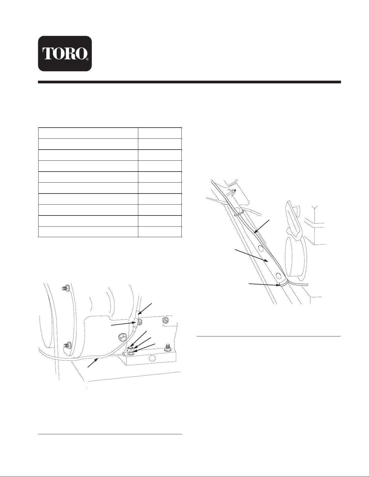
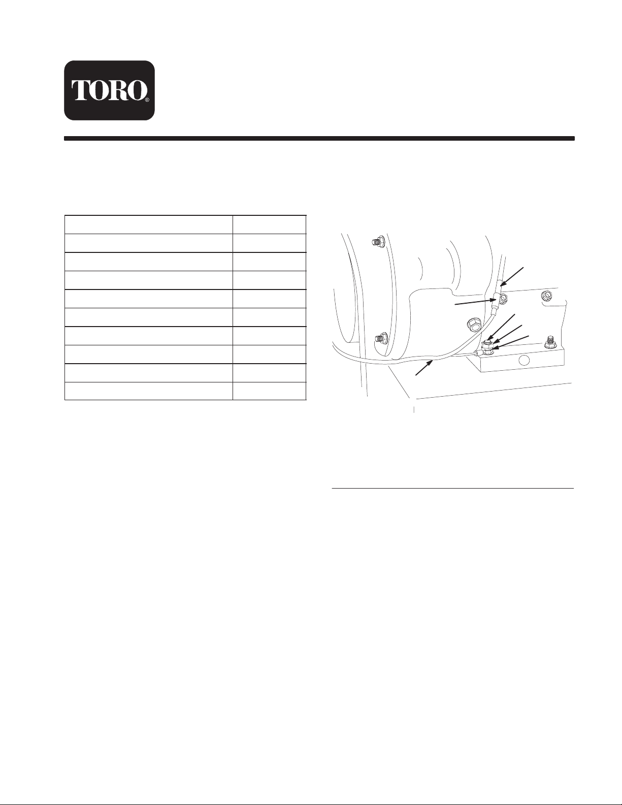
1. Secure the ring terminal of the wire harness to the
right rear engine mounting bolt with a serrated flange
locknut provided in the kit (Fig. 1).
Note: Position the ring terminal so that the wire
harness is routed toward the rear of the snowthrower
(Fig. 1).
2. Remove the rubber boot from the alternator connector
that hangs over the electric starter (Fig. 1).
3. Securely connect the wire harness connector to the
alternator connector (Fig. 1).
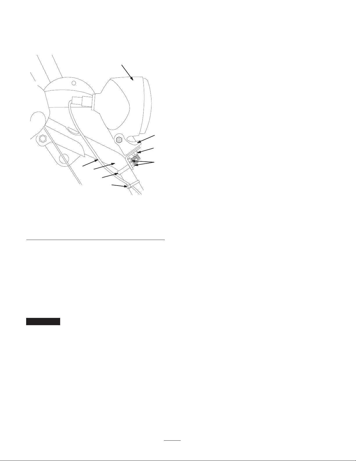
4. Secure the wire harness to the lower right side of the
handle assembly with a plastic cable tie (provided in
the kit) about an inch (2.5 cm) below the bottom end
of the upper handle (Fig. 2).
2
1
3
5
6
Figure 1
1. Right rear engine
mounting bolt
2. Serrated flange locknut
3. Ring terminal
2003—The Toro Company
8111 Lyndale A ve., Bloomington, MN 55420, USA
4. Alternator connector
5. Wire harness connector
6. Wire harness
4
Figure 2
1. Upper handle
1
2. Wire harness
3. Plastic cable tie
2
3
Printed in the USA
All Rights Reserved
Original Instructions (GB)
Page 2
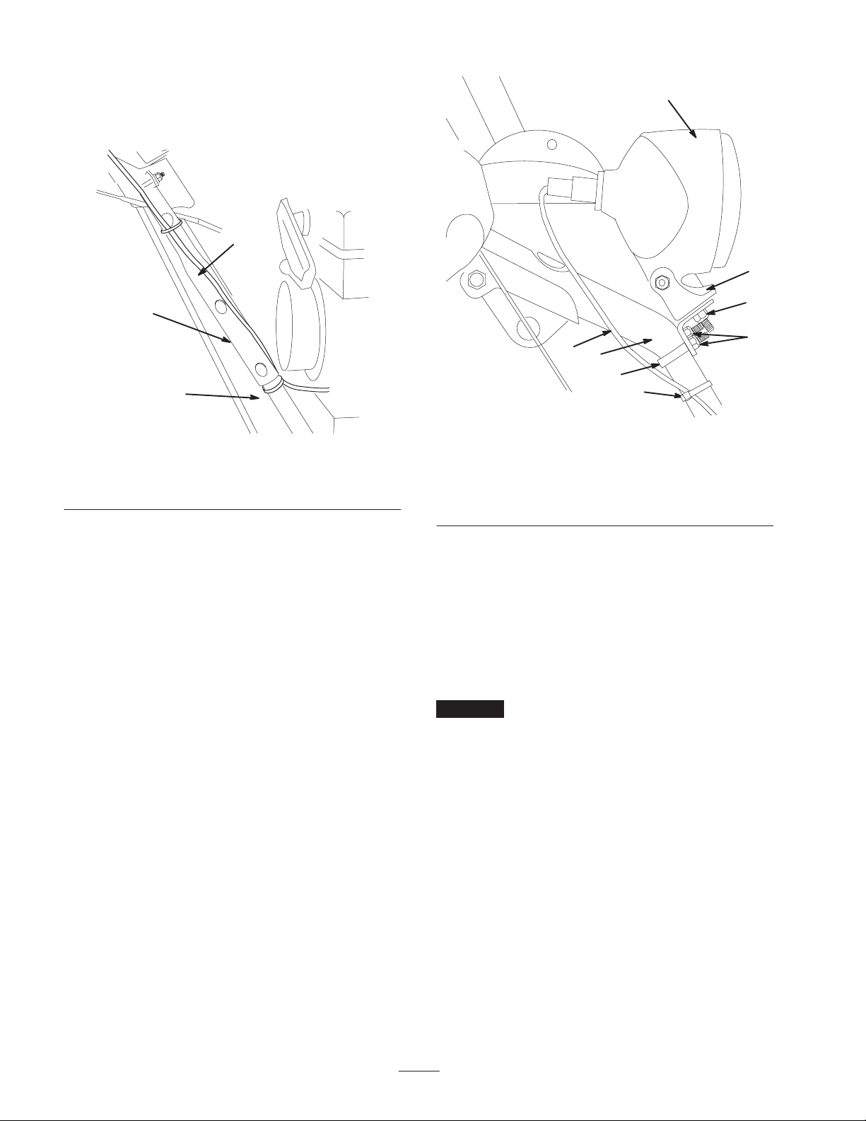
5. Secure the bracket to the right side of the handle using
the U-clamp, 2 washers, and 2 locknuts (1/4 in.)
provided in the kit (Fig. 3).
1
2
3
4
5
6
7
Figure 3
8
1. Headlamp
2. Bracket
3. Nut (5/16 In.)
4. Wire harness
5. Handle
6. U-bolt
7. Plastic cable tie
8. Locknuts (1/4 in.)
6. Secure the headlamp onto the bracket (Fig. 3) with the
nut (5/16 in.) provided in the kit.
7. Insert the wire connector (with the plastic clip on the
bottom) straight into the back of the headlamp until it
is securely in place (Fig. 3).
8. Secure the wire harness to the upper right side of the
handle assembly with a plastic cable tie (provided in
the kit) about an inch (2.5 cm) below the U-bolt
(Fig. 3).
Important Ensure that you do not pinch the wire
harness when you install it.
2
Page 3
Scheinwerfer-Kit
Power Max Schneefräse mit Lichtmaschine
Modellnr. 107-3827
Form No. 3351-124
Montageanleitung
Bewahren Sie diese Anleitungen mit der
Bedienungsanleitung auf.
Inhalt des Kits
BESCHREIBUNG MENGE
Scheinwerfer 1
Kabelbaum 1
U-Klemme 1
Halterung 1
Scheiben 2
Mutter, 5/16 Zoll 1
Sicherungsmutter, 1/4 Zoll 2
Gezackte Bundmutter 1
Kunststoffkabelbinde 1
Installieren des
Scheinwerfer-Kits
1. Befestigen Sie den Ringpol des Kabelbaums mit einer
gezackten Bundmutter aus dem Kit an der rechten
hinteren Motorbefestigungsschraube (Bild 1).
4
6
1. Rechte hintere Motorbefestigungsschraube
2. Gezackte Bundmutter
3. Ringpol
5
Bild 1
4. Lichtmaschinenanschluss
5. Kabelbaumanschluss
6. Kabelbaum
1
2
3
2003 – The Toro Company
8111 Lyndale A ve., Bloomington, MN 55420, USA
Hinweis: Positionieren Sie den Ringpol so, dass der
Kabelbaum zum Heck der Schneefräse verlegt ist
(Bild 1).
2. Nehmen Sie den Gummischuh vom Lichtmaschinenanschluss ab, der über dem Elektrostart hängt (Bild 1).
3. Befestigen Sie den Kabelbaumanschluss am
Lichtmaschinenanschluss (Bild 1).
Druck: USA
Alle Rechte vorbehalten
Übersetzung des Originals (D)
Page 4
4. Befestigen Sie den Kabelbaumanschluss mit einer
Kunststoffkabelbinde (aus dem Kit) unten rechts am
Griff, ungefähr 2,5 cm unter dem unteren Ende des
oberen Griffs (Bild 2).
2
1
2
1
3
Bild 2
1. Oberer Grif f
2. Kabelbaum
3. Kunststoffkabelbinde
5. Befestigen Sie die Halterung mit der U-Klemme, den
zwei Scheiben und zwei Sicherungsmuttern (1/4 Zoll)
aus dem Kit an der rechten Seite des Griffs (Bild 3).
3
8
4
5
6
7
Bild 3
1. Scheinwerfer
2. Halterung
3. Mutter (5/16 Zoll)
4. Kabelbaum
5. Griff
6. U-Schraube
7. Kunststoffkabelbinde
8. Sicherungsmutter (1/4 Zoll)
6. Befestigen Sie den Scheinwerfer mit der Schraube
(5/16 Zoll) aus dem Kit an der Halterung (Bild 3).
7. Stecken Sie den Kabelstecker (mit dem Kunststoffclip
unten) direkt hinten in den Scheinwerfer, bis er ganz
fest sitzt (Bild 3).
8. Befestigen Sie den Kabelbaum mit einer Kunststoff-
kabelbinde (aus dem Kit) oben rechts am Griff,
ungefähr 2,5 cm unter der U-Schraube (Bild 3).
Wichtig Stellen Sie sicher, dass Sie den Kabelbaum
bei der Montage nicht einquetschen.
4
Page 5

Kit phare
Déneigeuses Power Max avec alternateur
Modèle Nº 107-3827
Instructions d’installation
Form No. 3351-124
Conservez ces instructions avec le Manuel de l’utilisateur
à titre de référence.
Composition du kit
DESCRIPTION QUANTITÉ
Phare 1
Faisceau de câblage 1
Boulon en U 1
Support 1
Rondelles 2
Écrou 5/16 pouce 1
Contre-écrous 1/4 pouce 2
Contre-écrou à collerette dentelée 1
Serre-câble en plastique 1
Installation du kit phare
1. Fixez la cosse en anneau du faisceau de câble au
boulon de montage arrière droit du moteur au moyen
d’un contre-écrou à collerette dentelée fourni avec le
kit (Fig. 1).
4
6
1. Boulon d e montage arrière
droit du moteur
2. Contre-écrou à collerette
dentelée
3. Cosse en anneau
5
Figure 1
4. Connecteur de
l’alternateur
5. Connecteur du faisceau
de câblage
6. Faisceau de câblage
1
2
3
2003 – The Toro Company
8111 Lyndale A ve., Bloomington, MN 55420, États-Unis
Remarque : Placez la cosse en anneau de manière que
le faisceau de câblage soit acheminé vers l’arrière de
la déneigeuse (Fig. 1).
2. Retirez la gaine en caoutchouc du connecteur de
l’alternateur qui pend au-dessus du démarreur
électrique (Fig. 1).
3. Fixez solidement le connecteur du faisceau de câblage
au connecteur de l’alternateur (Fig. 1).
Imprimé aux États-Unis
Tous droits réservés
Traduction de l’original (F)
Page 6

4. Fixez le faisceau de câblage au côté inférieur droit de
l’ensemble guidon avec un serre-câble en plastique
(fourni avec le kit) à environ 2,5 cm au-dessous de
l’extrémité inférieure de la partie supérieure du guidon
(Fig. 2).
2
1
3
Figure 2
1. Partie supérieure du
guidon
2. Faisceau de câblage
3. Serre-câble en plastique
1. Phare
2. Support
3. Écrou 5/16 pouce
4. Faisceau de câblage
4
Figure 3
1
2
3
8
5
6
7
5. Guidon
6. Boulon en U
7. Serre-câble en plastique
8. Contre-écrous 1/4 pouce
5. Fixez le support au côté droit du guidon à l’aide du
boulon en U, de 2 rondelles et de 2 contre-écrous
(1/4 pouce) fournis avec le kit (Fig. 3).
6. Fixez le phare au support (Fig. 3) avec l’écrou
(5/16 pouce) fourni avec le kit.
7. Insérez le connecteur du câble (avec le serre-câble en
plastique en bas) directement au dos du phare jusqu’à
ce qu’il soit solidement fixé en position (Fig. 3).
8. Fixez le faisceau de câblage au côté supérieur droit de
l’ensemble guidon avec un serre-câble en plastique
(fourni avec le kit) à environ 2,5 cm au-dessous du
boulon en U (Fig. 3).
Important Veillez à ne pas pincer le faisceau de
câblage lors de l’installation.
6
Page 7

Kit faro
Spazzaneve Power Max con alternatore
Modello Nº 107-3827
Istruzioni per il montaggio
Form No. 3351-124
Conservate le presenti istruzioni insieme al Manuale
dell’operatore per future consultazioni.
Contenuto del kit
DESCRIZIONE QUANTITÀ
Faro 1
Cablaggio preassemblato 1
Morsetto ad U 1
Staffa 1
Rondelle 2
Dado 5/16 poll. 1
Dadi di bloccaggio 1/4 poll. 2
Dado di bloccaggio con flangia
zigrinata
Fascetta in plastica per cavi 1
1
Montaggio del Kit faro
1. Fissate il morsetto a spina tonda del cablaggio
preassemblato al bullone di fissaggio posteriore destro
del motore, utilizzando il dado di bloccaggio con
flangia zigrinata a corredo (Fig. 1).
4
6
1. Bullone di fissaggio
posteriore destro del
motore
2. Dado di bloccaggio con
flangia zigrinata
5
Figura 1
3. Morsetto a spina tonda
4. Connettore dell’alternatore
5. Connettore del cablaggio
preassemblato
6. Cablaggio preassemblato
1
2
3
2003 – The Toro Company
8111 Lyndale A ve., Bloomington, MN 55420, USA
Nota: Posizionate il morsetto a spina tonda in modo
che il cablaggio preassemblato sia diretto verso il retro
dello spazzaneve (Fig. 1).
2. Togliete la guaina di gomma dal connettore
dell’alternatore, che pende sopra l’avviamento
elettrico (Fig. 1).
3. Collegate saldamente il connettore del cablaggio
preassemblato al connettore dell’alternatore (Fig. 1).
Stampato negli USA
Tutti i diritti sono riservati
Traduzione del testo originale (I)
Page 8

4. Fissate il cablaggio preassemblato sul lato destro del
gruppo stegola, in basso, con una fascetta in plastica
per cavi (a corredo), circa 2,5 cm. sotto l’estremità
inferiore della stegola superiore (Fig. 2).
2
1
2
1
3
Figura 2
1. Stegola superiore
2. Cablaggio preassemblato
3. Fascetta in plastica per
cavi
5. Fissate la staffa sul lato destro della stegola utilizzando
il morsetto ad U, le due rondelle e i due dadi di
bloccaggio (1/4 poll.) a corredo (Fig. 3).
4
5
6
7
Figura 3
1. Faro
2. Staffa
3. Dado (5/16 poll.)
4. Cablaggio preassemblato
5. Stegola
6. Bullone ad U
7. Fascetta in plastica per
cavi
8. Dadi di bloccaggio
1/4 poll.
6. Fissate il faro sulla staffa (Fig. 3) con il dado
(5/16 poll.) a corredo.
7. Inserite a fondo il connettore serrafili (con il clip di
plastica in basso) sul retro del faro (Fig. 3).
8. Fissate il cablaggio preassemblato sul lato destro del
gruppo stegola, in alto, con una fascetta in plastica per
cavi (a corredo), circa 2,5 cm. sotto il bullone ad U
(Fig. 3).
3
8
Importante Prestate attenzione a non pizzicare il
cablaggio preassemblato in sede di montaggio.
8
Page 9

Lampesett
Power Max-snøfresere med generator
Modellnr. 107-3827
Form No. 3351-124
Installasjonsveiledning
Oppbevar denne veiledningen sammen med din
Brukerhåndbok slik at du har dem for fremtidig bruk.
Settets innhold
BESKRIVELSE ANTALL
Frontlys 1
Ledningsfastspenner 1
U-klemme 1
Brakett 1
Skiver 2
Mutter, 5/16 tommer 1
Låsemutter, 1/4 tomme 2
Sagtakket låsemutter med flens 1
Kabelsnor i plast 1
Installere lampesettet
1. Fest ringkoblingen på ledningsfastspenneren til høyre
monteringsbolt bak med en sagtakket låsemutter med
flens som medfølger i settet (fig. 1).
2. Fjern gummihetten fra generatorkoplingen som henger
over den elektriske starteren (fig. 1).
3. Fest ledningsfastspenneren godt til generatorkoplingen
(fig. 1).
4. Fest ledningsfastspenneren til høyre side nederst på
håndtaket med kabelsnoren i plast (medfølger i settet)
ca. 2,5 cm under nedsiden av det øvre håndtaket
(fig. 2).
2
1
3
4
5
1
2
6
Figur 1
1. Høyre monteringsbolt bak
2. Sagtakket låsemutter med
flens
3. Ringkobling
4. Generatorkopling
5. Ledningsfastspennerkobling
6. Ledningsfastspenner
Obs: Plasser ringkoblingen slik at ledningsfastspenneren ledes mot baksiden av snøfreseren (fig. 1).
2003 – The Toro Company
8111 Lyndale A ve., Bloomington, MN 55420, USA
3
Trykt i USA
Med enerett
1. Øvre håndtak
2. Ledningsfastspenner
Figur 2
3. Kabelsnor i plast
Oversettelse av originalen (N)
Page 10

5. Fest braketten til høyre side av håndtaket ved hjelp av
U-klemmen, to skiver og to låsemutre (1/4 tomme)
som medfølger i settet (fig. 3).
1
2
3
4
5
6
7
Figur 3
1. Frontlys
2. Brakett
3. Mutter (5/16 tomme)
4. Ledningsfastspenner
5. Håndtak
6. U-bolt
7. Kabelsnor i plast
8. Låsemutre (1/4 tomme)
6. Fest frontlyset i braketten (fig. 3) med mutteren
(5/16 tomme) som medfølger i settet.
7. Før ledningskontakten (med plastklemmen nederst)
rett inn bak i frontlyset til den sitter godt fast (fig. 3).
8. Fest ledningsfastspenneren til høyre side øverst på
håndtaket med kabelsnoren i plast (medfølger i settet)
ca. 2,5 cm) under U-bolten (fig. 3).
Viktig Pass på at ledningsfastspenneren ikke kommer i
klemme når du installerer den.
8
10
Page 11

Belysningssats
Power Max snöslungor med generator
Modellnr 107-3827
Form No. 3351-124
Monteringsinstruktioner
Spara de här instruktionerna tillsammans med din
bruksanvisning för framtida referens.
Satsens innehåll
BESKRIVNING MÄNGD
Strålkastare 1
Ledningsnät 1
U-klämma 1
Fäste 1
Brickor 2
Mutter, 5/16” 1
Låsmuttrar, 1/4” 2
Räfflad låsmutter med fläns 1
Kabelband i plast 1
Montera belysningssatsen
1. Montera ledningsnätets ringkoppling på den högra
motorfästbulten bak med en räfflad låsmutter med
fläns som medföljer i satsen (fig. 1).
2. Ta bort gummiskon från generatoranslutningen som
hänger över elstarten (fig. 1).
3. Koppla ihop ledningsnätanslutningen och generator-
anslutningen ordentligt (fig. 1).
4. Montera ledningsnät et på den undre högra sidan av
handtaget med ett kabelband i plast (medföljer i satsen)
ca 2,5 cm under det övre handt aget s nedre ände (fig. 2).
2
1
3
4
5
1
2
6
Figur 1
1. Höger motorfästbult bak
2. Räf flad låsmutter med fläns
3. Ringkoppling
4. Generatoranslutning
5. Ledningsnätanslutning
6. Ledningsnät
Observera: Placera ringkopplingen så att ledningsnätet
är draget mot snöslungans bakre del (fig. 1 ).
2003 – The Toro Company
8111 Lyndale A ve., Bloomington, MN 55420, USA
3
1. Övre handtag
2. Ledningsnät
Tryckt i USA
Med ensamrätt
Figur 2
3. Kabelband i plast
Översättning av originalet (S)
Page 12

5. Montera fästet på handtagets högra sida med
U-klämman, två brickor och två låsmuttrar (1/4”) som
medföljer i satsen (fig. 3).
1
2
3
4
5
6
7
Figur 3
1. Strålkastare
2. Fäste
3. Mutter (5/16”)
4. Ledningsnät
5. Handtag
6. U-bult
7. Kabelband i plast
8. Låsmuttrar (1/4”)
6. Montera strålkastaren på fästet (fig. 3) med muttern
(5/16”) som medföljer i satsen.
7. För in ledningsanslutningen (med plastklämman i
änden) rakt in i strålkastarens baksida, tills den sitter
fast ordentligt (fig. 3).
8. Montera ledningsnätet på den övre högra sidan av
handtaget med ett kabelband i plast (medföljer i
satsen) ca 2,5 cm under U-bulten (fig. 3).
Viktigt Kontrollera att du inte nyper fast ledningsnätet
när du monterar det.
8
12
Page 13

Valosarja
Power Max Laturilla varustetut lumilingot
Mallinro. 107-3827
Form No. 3351-124
Asennusohjeet
Säilytä nämä ohjeet käyttöoppaan kanssa tulevaa tarvetta
varten.
Sisältö
KUVAUS MÄÄRÄ
Ajovalo 1
Johdinsarja 1
U-liitin 1
Kannatin 1
Aluslevyt 2
Mutteri, 5/16” 1
Lukkomutterit, 1/4” 2
Hammastettu laippalukkomutteri 1
Muovinen nippuside 1
Valosarjan asennus
1. Kiinnitä johtosarjan rengasliitin moottorin oikean-
puoleiseen taka-asennuspulttiin mukana toimitetulla
hammastetulla laippalukkomutterilla (kuva 1).
2. Irrota kumisuojus sähkökäynnistimen yläpuolella
riippuvasta laturin liittimestä (kuva 1).
3. Kytke johdinsarjan liitin tiukasti laturin liittimeen
(kuva 1).
4. Kiinnitä johdinsarj a oike an kahvan alaosaa n muovi sella
nippusiteellä (pakka uksessa) noi n 2,5 cm:n pää hän
yläkahvan ala päästä (kuva 2 ).
2
1
3
4
5
1
2
3
6
Kuva 1
1. Moottorin oikeanpuoleinen
taka-asennuspultti
2. Hammastettu
laippalukkomutteri
3. Rengasliitin
4. Laturin liitin
5. Johdinsarjan liitin
6. Johdinsarja
Huomautus: Sijoita rengasliitin siten, että johdinsarja
kulkee lumilingon takaosaan päin (kuva 1).
2003 – The Toro Company
8111 Lyndale A ve., Bloomington, MN 55420, USA
1. Yläkahva
2. Johdinsarja
Painettu Yhdysvalloissa
Kaikki oikeudet pidätetään
Kuva 2
3. Muovinen nippuside
Käännös alkutekstistä (SF)
Page 14

5. Kiinnitä kannatin kahvan oikealle puolelle
U-liittimellä, kahdella aluslevyllä ja kahdella
1/4 tuuman lukkomutterilla (pakkauksessa) (kuva 3).
1
2
3
4
5
6
7
Kuva 3
1. Ajovalo
2. Kannatin
3. Mutteri (5/16 tuumaa)
4. Johdinsarja
5. Kahva
6. U-pultti
7. Muovinen nippuside
8. Lukkomutterit, 1/4”
6. Kiinnitä ajovalo kannattimeen (kuva 3) mukana
toimitetulla 5/16 tuuman mutterilla.
7. Työnnä johdinliitintä (jonka muovinipistin on
alapäässä) suoraan ajovalon takaosaan, kunnes se on
tiukasti paikallaan (kuva 3).
8. Kiinnitä johdinsarja oikean kahvan yläosaan
muovisella nippusiteellä (pakkauksessa) noin 2,5 cm
U-pultin alapuolelle (kuva 3).
Tärkeää Varo, että johdinsarja ei joudu puristuksiin
asennuksen yhteydessä.
8
14
Page 15

Page 16

 Loading...