

Toro 107-3816, 107-3817 Installation Instructions
Drift Breaker Kit
For Power Max® Snowthrowers
Model No. 107-3816
Model No. 107-3817
Installation
Loose Parts
Use the chart below to verify that all parts have been shipped.
Form No. 3355-309 Rev A
Installation Instructions
Step
Template
Side breaker
Top breaker
1
Carriage bolt, (5/16 x 3/4 inches)
Carriage bolt, (5/16 x 1 inch)
Locknut, 5/16 inch
Description
Qty.
1
2
1
4
2
6
Install the drift breaker on the
snowthrower.
Use
Note: Visit www .T oro .com and do wnload the F renc h Operator’ s Manual that cor responds to the model
and serial n umber of the product on whic h this kit is installed.
Step
1
Installing the Drift Breaker
on the Snowthrower
Parts needed for this step:
1
Template
2
Side breaker
1
Top breaker
4
Carriage bolt, (5/16 x 3/4 inches)
2
Carriage bolt, (5/16 x 1 inch)
6
Locknut, 5/16 inch
Procedure
1. T rim off the template along the dotted line .
2. P osition the template (printed side out) on the
right side of the aug er housing aligning the
dotted line (previously cut) edg e with the top
of the aug er housing and the right side of the
template with the front edg e of the housing
( Figure 1 ).
© 2006—The Toro® Company
8111 Lyndale Avenue South
Bloomington, MN 55420
Register at www.Toro.com. Original Instructions (EN)
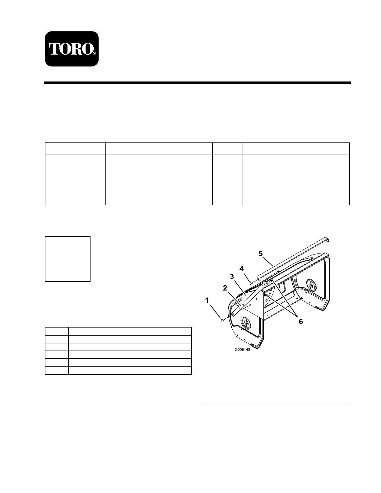
Figure 1
1. Carriage bolt, 5/16 x 3/4
inches (4)
2. Side breaker (2)
3. Template
4. Carriage bolt, 5/16 x 1 inch
(2)
5. Top edge of side breaker
6. Top breaker
7. Locknut (6)
3. Secure the template in place with tape and
center punc h through the hole on the template
and onto the sno wthro w er side frame .
4. Measure 4 inc hes (10.2 cm) do wn along the
diag onal line and mark the spot on that line .
Printed in the USA.
All Rights Reserved

5. Punc h through the mark y ou made on the
template and onto the sno wthro w er side frame .
6. R emo v e the template .
7. T ur n the template o v er (printed side in) and
position it on the left side of the aug er housing,
aligning it with the top and front edg es of the
aug er housing .
8. Use the holes previously punc hed in the
template and center punc h eac h hole location.
9. At eac h of the punc hed locations , drill a 21/64
inc h (0.83 cm) diameter hole .
10. Mount a side break er to eac h side of the
housing with 2 car riag e bolts (5/16 x 3/4
inc hes) and 2 loc kn uts ( Figure 1 ).
Note: Ensure that the top edg e of the side
break er is parallel to the g round ( Figure 1 ).
11. Mount the top break er o v er the top ends of the
side break ers and secure them with 2 car riag e
bolts (5/16 x 1 inc h) and 2 loc kn uts ( Figure 1 ).
2
Kit brise -congères
Déneigeuses Power Max®
N° de modèle 107 -3816
N° de modèle 107 -3817
Mise en service
Pièces détachées
Reportez -vous au tableau ci -dessous pour vérier si toutes les pièces ont été expédiées.
Form No. 3355 -309 Rev A
Instructions d'installation
Étape
Gabarit
Brise -congères latéral
Brise -congères supérieur
1
Boulon de carrossier (5/16 x 3/4")
Boulon de carrossier (5/16 x 1
pouce)
Contre -écrou 5/16"
Description
Qté
1
2
1
4
2
6
Montage du brise -congères sur la
déneigeuse.
Utilisation
Remarque: R endez -v ous sur le www .T oro .com et téléc harg ez, le Manuel de l’utilisateur en français
cor respondant au modèle et au n uméro de série du produit por tant ces autocollants .
fraise et le côté droit du g abarit a v ec le bord
a v ant du car ter ( Figure 1 ).
1
Montage du brise -congères
sur la déneigeuse
Pièces nécessaires pour cette
opération :
1
Gabarit
2
Brise -congères latéral
1
Brise -congères supérieur
4
Boulon de carrossier (5/16 x 3/4")
2
Boulon de carrossier (5/16 x 1 pouce)
6
Contre -écrou 5/16"
Procédure
1. Découpez le g abarit le long des pointillés .
2. Placez le g abarit (côté imprimé à l'extérieur)
sur le côté droit du car ter de la fraise . Alignez
le côté où figure le trait en pointillés (découpé
précédemment) a v ec le haut du car ter de la
© 2006—The Toro® Company
8111 Lyndale Avenue South
Bloomington, MN 55420
Enregistrez votre produit à www.Toro.com
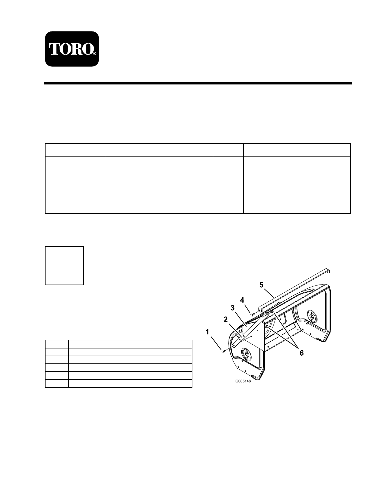
Figure 1
1. Boulon de carrossier 5/16
x 3/4" (4)
2. Brise -congères latéral (2)
3. Gabarit
4. Boulon de carrossier 5/16
x 1" (2)
5. Bord supérieur du
brise -congères
6. Brise -congères supérieur
7. Contre -écrou (6)
3. Fix ez le g abarit en place a v ec du r uban adhésif
et mar quez au pointeau l'emplacement de
Traduction du texte d'origine (FR)
Imprimé aux États -Unis.
Tous droits réservés
 Loading...