

Page 1
Snow Cab Kit
Power Max Snowthrowers
Model No. 107-3814
Form No. 3351-212
Installation Instructions
Save these instructions with your Operator ’s Manual for
future reference.
Warning
Installing this snow cab onto a Power Max
snowthrower without properly installing a
counterweight to the front of the snowthrower can
cause it to tip backward and fall on the operator,
causing injury.
• Do not operate a snowthrower with a snow cab
that does not have the proper counterweight.
• Obtain and install a Toro weight kit to the front
of the snowthrower in order to balance the
added weight of the snow cab.
Contents of the Kit
DESCRIPTION QUANTITY
U-brackets 2
Washers 4
End caps 2
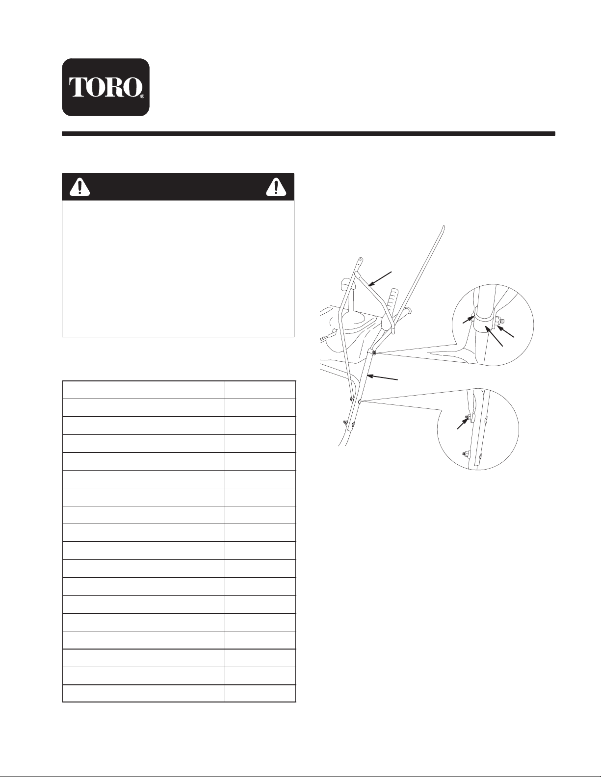
Installing the Snow Cab Frame
on the Snowthrower
1. Remove the 2 upper handle nuts (1 on each side) from
the snowthrower handle assembly (Fig. 1) and save
them for step 2.
6
4
5
3
1
2
Headlight extension bar 1
Bolts, 1/4 x 1 in. 2
Bolts, 1/4 x 3/4 in. 6
Bolts, 1/4 x 1-3/4 in. 2
Locknuts, 1/4 in. 10
Bolt, 5/16 x 3/4 in. 1
Flange locknut, 5/16 in. 1
Top frame 1
Rear frame 1
Horizontal frame 1
Left mounting bracket 1
Right mounting bracket 1
Front posts 2
Cover 1
2003—The Toro Company
8111 Lyndale A ve., Bloomington, MN 55420, USA
1. Handle assembly
2. Upper handle nut (2)
3. U-bracket (2)
2. Install the lower front end of the left and right
mounting brackets onto the handle assembly using the
upper handle mounting nuts you removed in step 1
(Fig. 1).
3. Install the other lower end of each mounting bracket
onto the handle assembly with a U-bracket, bolt (1/4 x
1-3/4 in.), and locknut (Fig. 1).
Note: You may need to squeeze each U-bracket together
slightly before installing it onto the handle assembly.
Note: The ends of the U-brackets should face downward.
Printed in the USA
All Rights Reserved
m-7249
Figure 1
4. Bolt, 1/4 x 1-3/4 in. (2)
5. Locknut (2)
6. Left mounting bracket
Original Instructions (EN)
Page 2
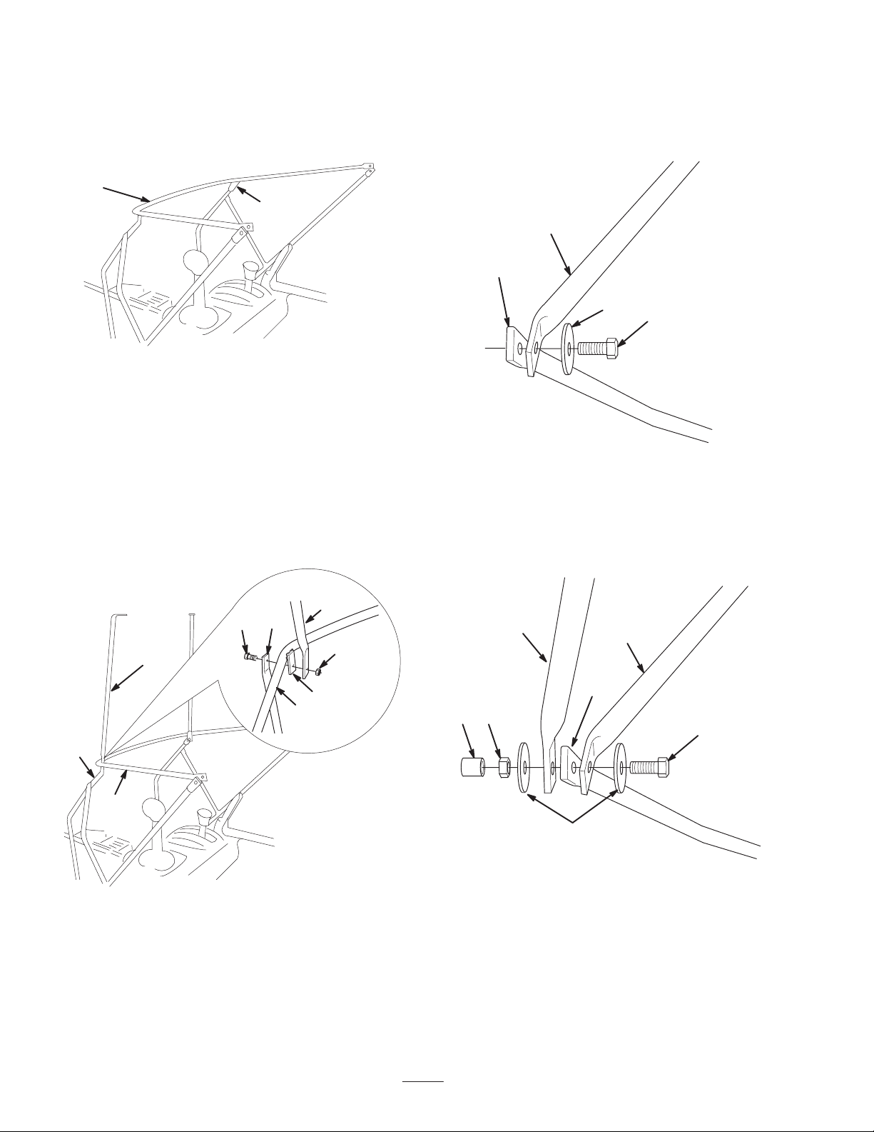
4. Position the horizontal frame inside the upper ends of
the mounting brackets (Fig. 2).
Note: Position the horizontal frame with the 2 front
tabs downward (see inset in Figure 3).
1
2
7. Repeat step 6 for the other front post.
8. For each side, align the holes in the frame ends in the
rear, insert a bolt (with a washer) through the holes
from the inside (Fig. 4).
2
1
m-7250a
Figure 2
1. Horizontal frame 2. Upper end of mounting
bracket (4)
5. Align each of the 2 holes in the front corners and insert
a bolt (1/4 x 3/4 in.) from the outside through each of
the holes and install locknuts on the bolts until they are
finger tight.
6. Remove a locknut that you just installed on one of the
front corners in step 5, install the bottom (straight) end
of a front post and a locknut onto the bolt, and tighten
the locknut until the front post stays upright (Fig. 3).
3
2
1
6
3
5
4
m-2699
2
3
4
Figure 4
1. Mounting bracket end (2)
2. Horizontal frame
3. Washer (2)
4. Bolt, 1/4 x 1 in. (2)
9. Position the rear frame with the top tabs facing
forward and the bottom ends to the outside of the other
frame ends (Fig. 5).
3
5
4
1
7
6
m-2700
4
m-7250
Figure 3
1. Bolt, 1/4 x 3/4 in. (2)
2. Upper end of mounting
bracket (2 in the front)
3. Front post (2)
4. Horizontal frame
5. Tab (2)
6. Locknut (2)
Note: The tabs at the top of the front post should face in
toward the operating position.
2
Figure 5
1. Locknut (2)
2. Washers (4)
3. Rear frame
4. Mounting bracket (2)
5. Horizontal frame
6. Bolt, 1/4 x 1 in. (2)
7. End cap (2)
10.Install a washer and a locknut on each of the bolts and
tighten each locknut until it is finger tight.
2
m-2700
Page 3

11. Hold the rear frame upright and tighten the locknuts
(Fig. 5).
Note: Do not overtighten the locknuts because you
will need to adjust the frame assembly to install the
top frame and the cover.
2
1
4
12.Attach the top frame to the front posts (Fig. 6) and to
the rear frame (Fig. 7) with 4 bolts (1/4 x 3/4 in.) and
4 locknuts.
Note: Insert the bolts from the bottom.
1
4
3
2
1
m-2702
2
3
3
m-2701
m-7252a
Figure 7
1. Locknut (2)
2. Rear frame
3. Top frame
4. Bolt, 1/4 x 3/4 in.
13.From the operating position, move the entire frame
assembly forward until the rear frame is at a 90-degree
angle to the horizontal frame. (Fig. 8).
Note: Ensure that the horizontal frame is parallel to
the ground. If it is not, adjust the U-brackets (step 3).
1
1. Top frame
2. Front post (2)
Figure 6
3. Bolt, 1/4 x 3/4 in.
4. Locknut (2)
90
2
m-2696
Figure 8
1. Rear frame 2. Horizontal frame
14.Tighten all fasteners securely and insert the end caps
on the bolt ends that extend from the washers (Fig. 5).
3
Page 4

Installing the Headlight
Installing the Cover
Extension Bar
If your snowthrower has a headlight, you will need to
move the headlight.
1. Loosen the nuts that hold the headlight bracket onto
the right side of the handle (Fig. 9).
1
2
m-7011
Figure 9
1. Headlight
2. Bracket
2. Rotate the headlight bracket to the right 90 degrees
(Fig. 9) and tighten the nuts.
3. Install the headlight extension bar with a bolt (5/16 x
3/4 in.) and a flange locknut (5/16 in.) and secure the
headlight to the bar.
3
3. Nut (2)
1. Open the 2 slits in the cover to allow room for the
chute control rod and the headlight extension bar.
2. Slip the cover over the frame assembly and close the
snaps to secure the cover around the top and rear
frames (Fig. 11).
1
3
2
4
m-2697
Figure 11
1. Top flap
2. Rear frame
3. Top frame
4. Side flap
3. Close the slits around the chute control bar and
headlight extension bar.
Note: The front of the snow cab should be slightly
forward from vertical when the snowthrower is not in use
(Fig. 12).
1. Headlight extension bar
(shown with cover)
1
m-7253
Figure 10
m-7253
Figure 12
1. Cover
4
 Loading...