

Page 1

Replacement Handle Kit
100 Series Z Masters with ROPS
Part No. 107–3089
Loose Parts
Note: Use the chart below to verify all parts have been shipped.
Step Description Qty. Use
Form No. 3350-728
Installation Instructions
1
2
3
4
5
6
No parts needed – Removing the bagger arm
Bagger arm 1 Installing the bagger arm
Foam grip 1 Installing the latch lever
Cable
Short clevis
Clevis pin
Cotter pin
No parts needed – Adjusting the bagger arm
Weight
Weight bracket
Large Washer
Locknut, 5/16 inch
Bolt, 5/16 x 1–1/4 inch
Washer, 11/32
1
1
1
1
1
2
2
2
2
2
Installing the new cable
Installing the weight
2003 by The Toro Company
8111 Lyndale Avenue South
Bloomington, MN 55420-1196
Contact us at www.Toro.com
All Rights Reserved
1
Printed in the USA
Page 2
Step
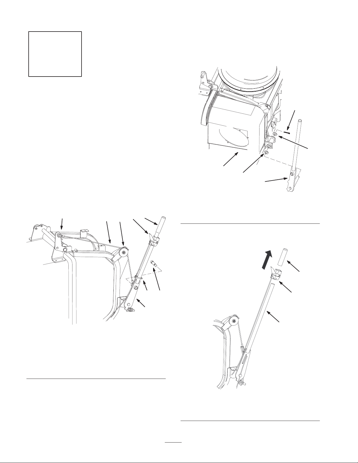
7. Remove the cotter pin and washer from the bagger arm
(Fig. 2). Save the washer and cotter pin.
8. Slide the bagger arm and washer out from the bagger
frame (Fig. 2). Save the washer.
1
Removing the Existing Bagger
Arm
No parts needed for this step.
Procedure
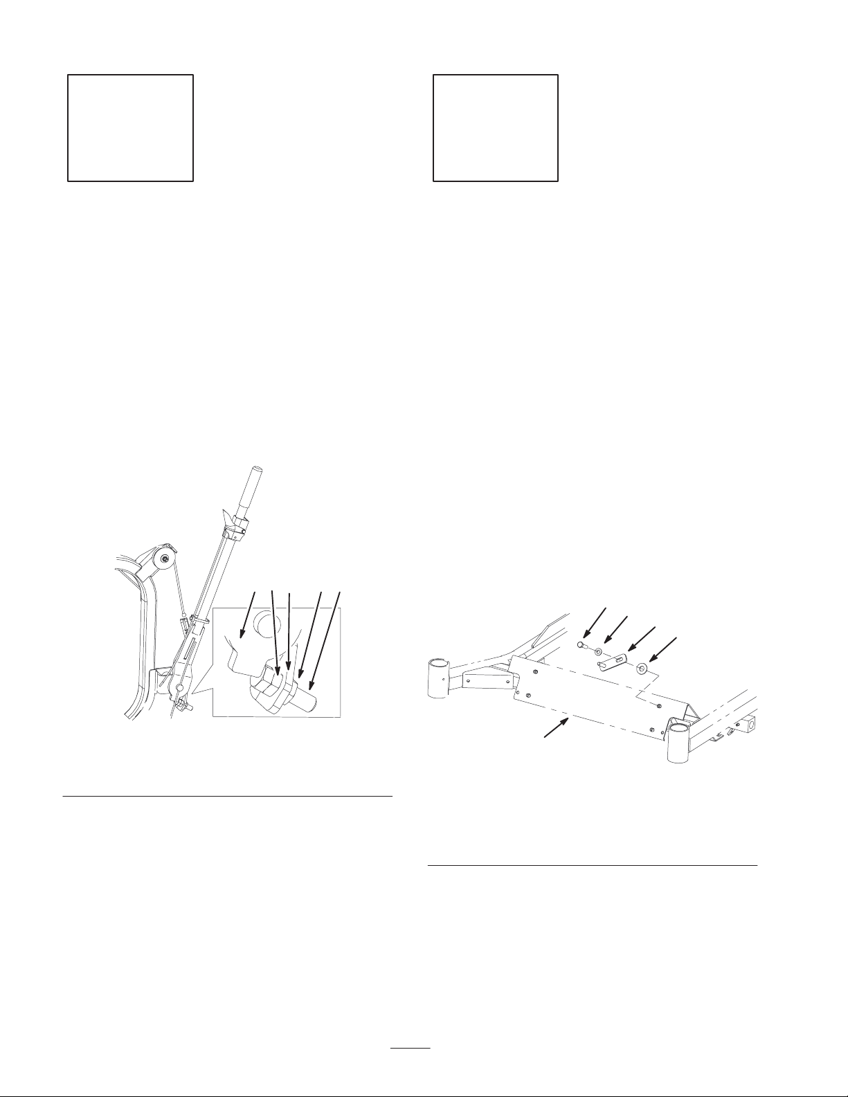
1. Remove the shoulder bolt and cable from the bagger
arm (Fig. 1).
2. Loosen the nut and pulley on the bagger and remove the
cable from the pulley (Fig. 1).
3. Remove the cable from the bagger door hinge (Fig. 1).
Save all the hardware.
5
2
4
7
8
3
2
m–6206
1. Bagger arm
2. Bagger
9. Remove the latch lever off of the bagger arm and
discard the the bagger arm (Fig. 3).
4
1
Figure 2
3. Cotter pin
4. Washer
4
1
m–6136
Figure 1
1. Bagger arm
2. Cable
3. Shoulder bolt
4. Pulley and nut
4. Loosen the setscrew holding the latch lever (Fig. 5).
5. Remove the plastic cable ties on the handle and slide
the latch lever down the handle (Fig. 1).
6. Remove the grip from the bagger arm (Fig. 3).
5. Bagger door hinge
6. Cable tie
7. Latch lever
8. Grip
3
36
Figure 3
1. Bagger Arm
2. Latch lever
3. Foam grip
2
1
m–7173
2
Page 3
Step
2
Installing the Bagger Arm
Parts needed for this step:
• 1 Dump handle
Procedure
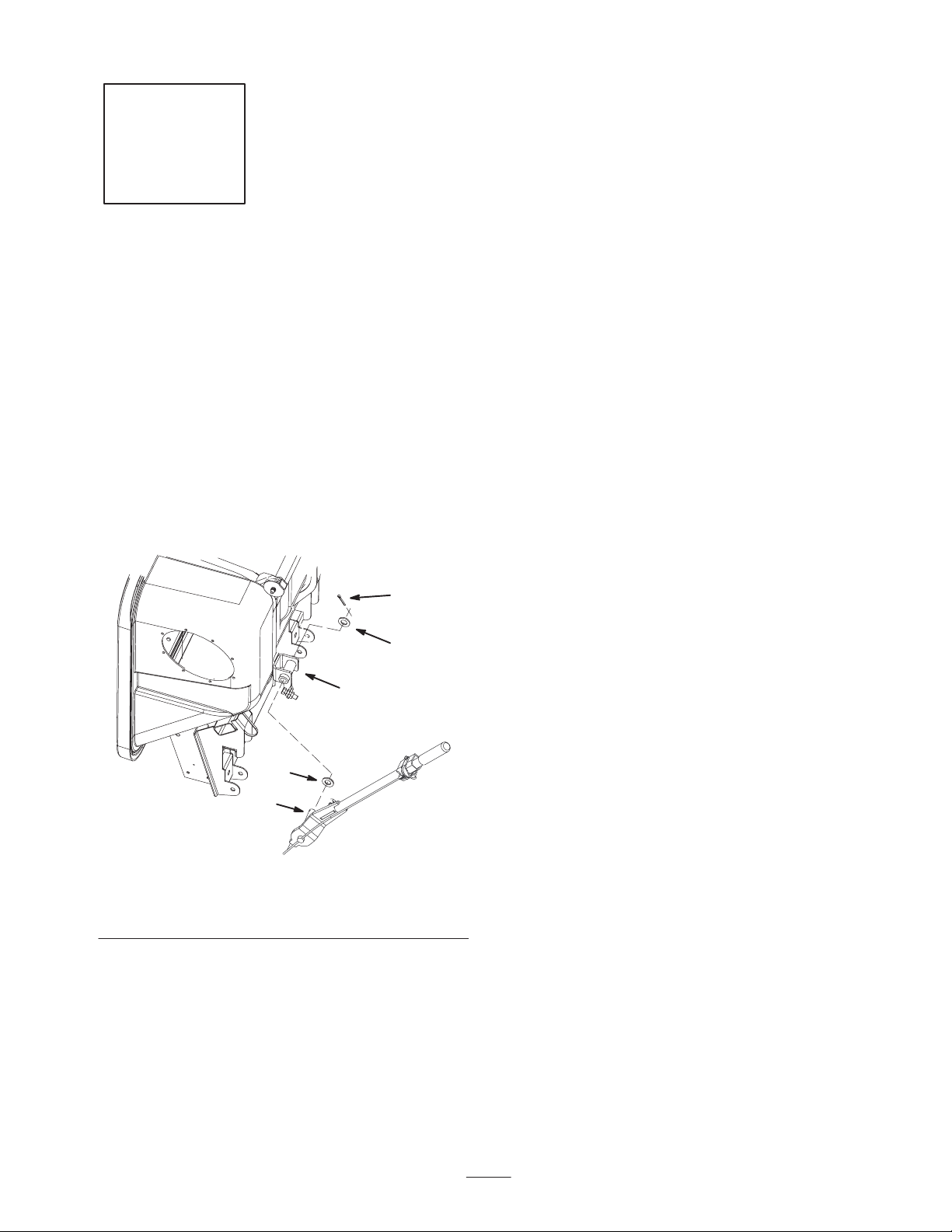
1. Install the latch lever onto the bagger arm.
2. Install 1 washer previously removed onto the bagger
arm pivot and install the bagger dump handle into the
bagger frame (Fig. 4).
3. Secure the bagger handle with the previously removed
washer and cotter pin (Fig. 4).
1. Bagger arm pivot
2. Washer
3
2
4
2
1
m–7170
Figure 4
3. Cotter pin
4. Bagger frame
3
Page 4
Step
3
Installing the Latch Lever
4
3
1
2
Parts needed for this step:
• 1 Foam grip
Procedure
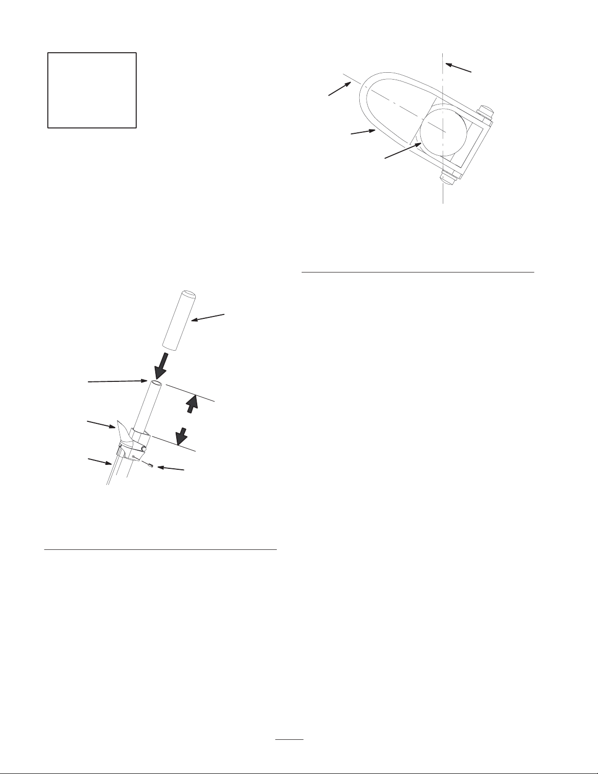
1. Position the latch lever 5 inches (12.7 cm) down from
the end of the bagger arm. See Figure 5.
6
1
2
3
Figure 5
1. Bagger arm end
2. Latch lever position
3. Latch lever cable
5
4
m–7175
4. Set screw
5. 5 inches (12.7 cm)
6. Foam grip
m–7176
Figure 6
End view of handle
1. Latch lever
2. End of handle
3. Tighten the setscrew that holds the latch lever (Fig. 5).
4. Install the cable ties (Fig. 7).
5. Install the foam grip onto the bagger arm (Fig. 5).
3. 10 o’clock position
4. 12 o’clock position
2. Position the latch lever at the 10 o’clock position when
looking at the end of the handle (Fig. 6).
4
Page 5
Step
2
4
4
Installing the New Cable
Parts needed for this step:
• 1 Cable
• 1 Clevis pin
• 1 Clevis
• 1 Cotter pin
Procedure
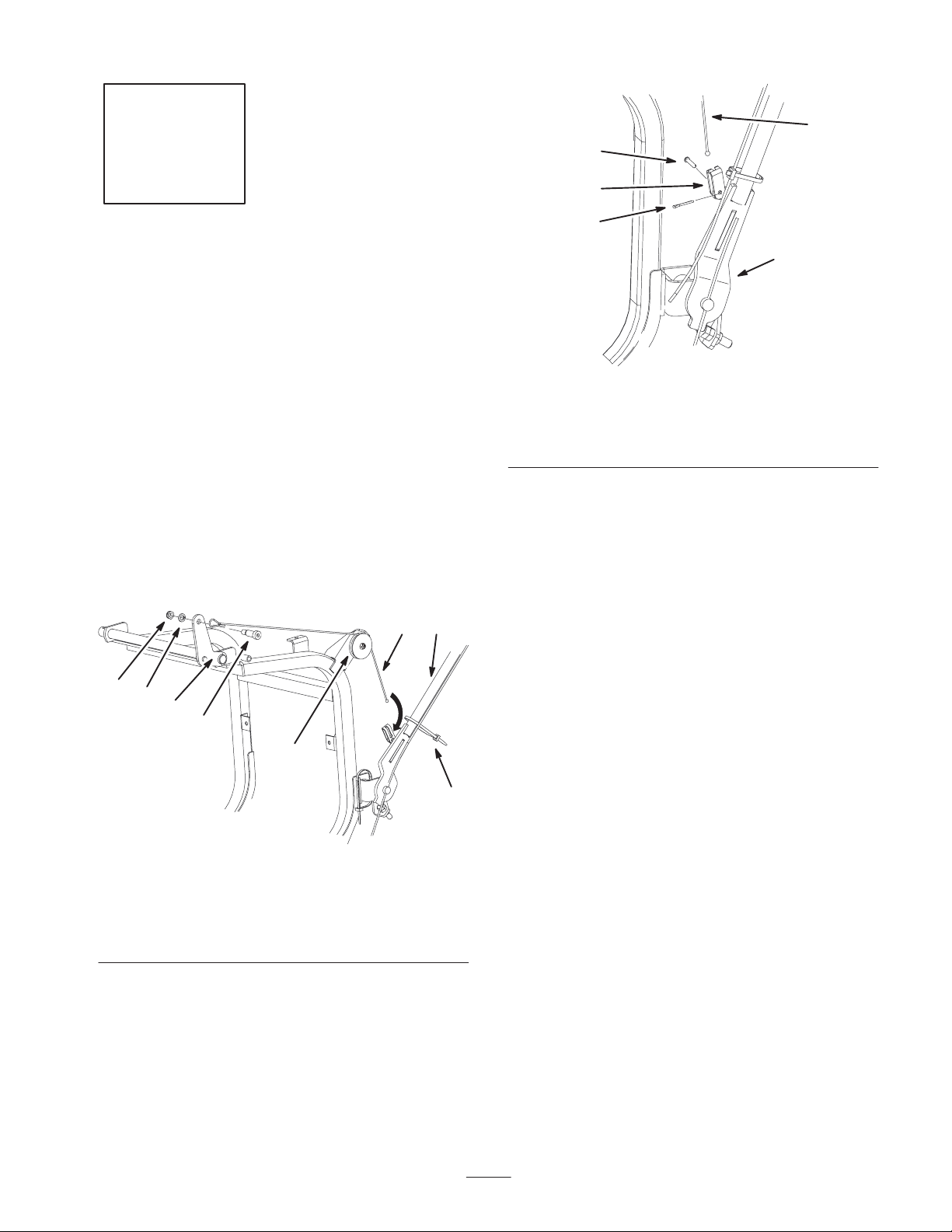
1. Install the new cable to the top of the bagger with the
previously removed shoulder bolt, washer and nut
(Fig. 7).
2. Install the cable into the pulley and tighten the nut
(Fig. 7).
2
1
3
5
1
m–7174
Figure 8
1. Bagger arm
2. Bagger cable
3. Cable clevis
5. Adjust the handle stop, refer to Adjusting the Bagger
Arm, page 6.
4. Clevis pin
5. Cotter pin
7
8
5
3
4
m–7171
Figure 7
1. Bagger arm
2. Cable
3. Shoulder bolt
4. Pulley and nut
3. Secure the bagger cable clevis to the bagger arm with
the clevis pin and cotter pin (Fig. 8).
4. Install the cable into the cable clevis installed on the
bagger handle (Fig. 8).
5. Bagger door hinge
6. Cable tie
7. Nut
8. Washer
6
5
Page 6
Step
Step
5
No parts needed for this step.
Adjusting the Bagger Arm
The bagger arm needs to be adjusted to remove slack in the
bagger cable.
1. Loosen the nuts on both sides of the stop bracket
(Fig. 9).
2. Adjust the stop bolt until there is no slack in the bagger
cable (Fig. 9).
3. Tighten the nuts on both sides of the stop bracket
(Fig. 9).
1 4 243
6
Installing the Weight
Parts needed for this step:
• Weight
• Weight bracket
• Washer,
• Locknut, 5/16 inch
• Bolt, 5/16 x 1–1/4 inch
• Washer,
Procedure
1. Remove the existing top bolts and washers from the
front of the footpan. Save the washers.
2. Install the weight brackets to the front of the footpan
with 2 bolts (5/16 x 1–1/4 inch) and 2 washers ( inch)
and 2 washers previously removed (Fig. 10).
4
3
2
5
m–7179
1. Bagger arm
2. Stop bracket
Figure 9
3. Stop bolt
4. Nut
m–7168
1. Front of footpan
2. Weight bracket
3. Previously removed
washer
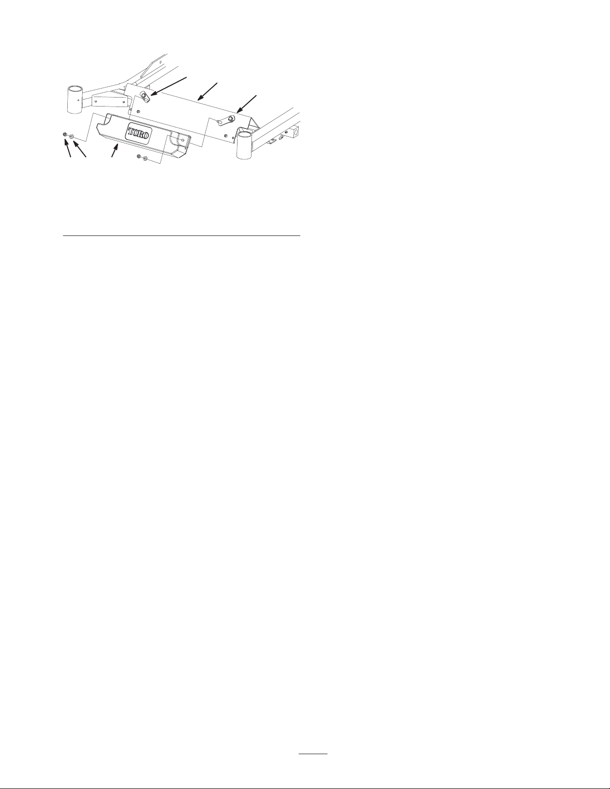
3. Install the weight onto the weight brackets with
2 washers (5/16 inch) and 2 locknuts (5/16 inch)
(Fig. 11).
6
1
Figure 10
4. Bolt, 5/16 x 1–1/4 inch
5. Large washer
Page 7
5 2
4
1. Front of footpan
2. Weight
3. Weight bracket
3
Figure 11
4. Locknut, 5/16 inch
5. Washer, 11/32 inch
1
3
m–7169
7
Page 8

8
 Loading...