

Page 1

Form No. 3350-456 Rev A
Roll Over Protection System Kit
100 Series Z Masters
Part No. 107–3066
Installation Instructions
Note: This kit is used for replacing an existing ROPS or adding it to a machine without an existing ROPS.
Loose Parts
Note: Use the chart below to identify parts for assembly.
Step Description Qty. Use
1
2
3
4
5
6
7
8
No parts needed – Raising the machine up
No parts needed – Removing the rear tires
Template 1 Drilling holes for the ROPS
No parts needed – Removing the existing seat
Seat frame 1 Installing the new seat frame
Seat latch catch
Bolt, 5/16 x 7/8 inch
Locknut, 5/16 inch
Seat belt
Bolt, 7/16 x 1 inch
Locknut, 7/16 inch
Roll bar, right section
Roll bar, left section
Roll bar, center section
Bolt, 3/8 x 1 inch
Curved washer, 3/8 inch
Flange nut, 3/8 inch
Bolt, 1/2 x 3-1/4 inches
Flange nut, 1/2 inch
Lanyard
1
2
2
1
2
2
1
1
1
8
8
8
2
2
2
Installing the new seat latch catch
Installing the seat belt
Installing the roll over protection system
(ROPS)
Domestic footrest decal
9
10
11
2003—The Toro Company
8111 Lyndale A ve., Blomington, MN 55420, USA
International footrest decal
International ROPS decal
Wheels 2 Installing the drive wheels
No parts needed – Checking the tire pressure
1
1
1
Printed in the USA
All Rights Reserved
Installing the Decals
Original Instructions (EN)
Register your product at www.Toro.com
Page 2
2
Step
1
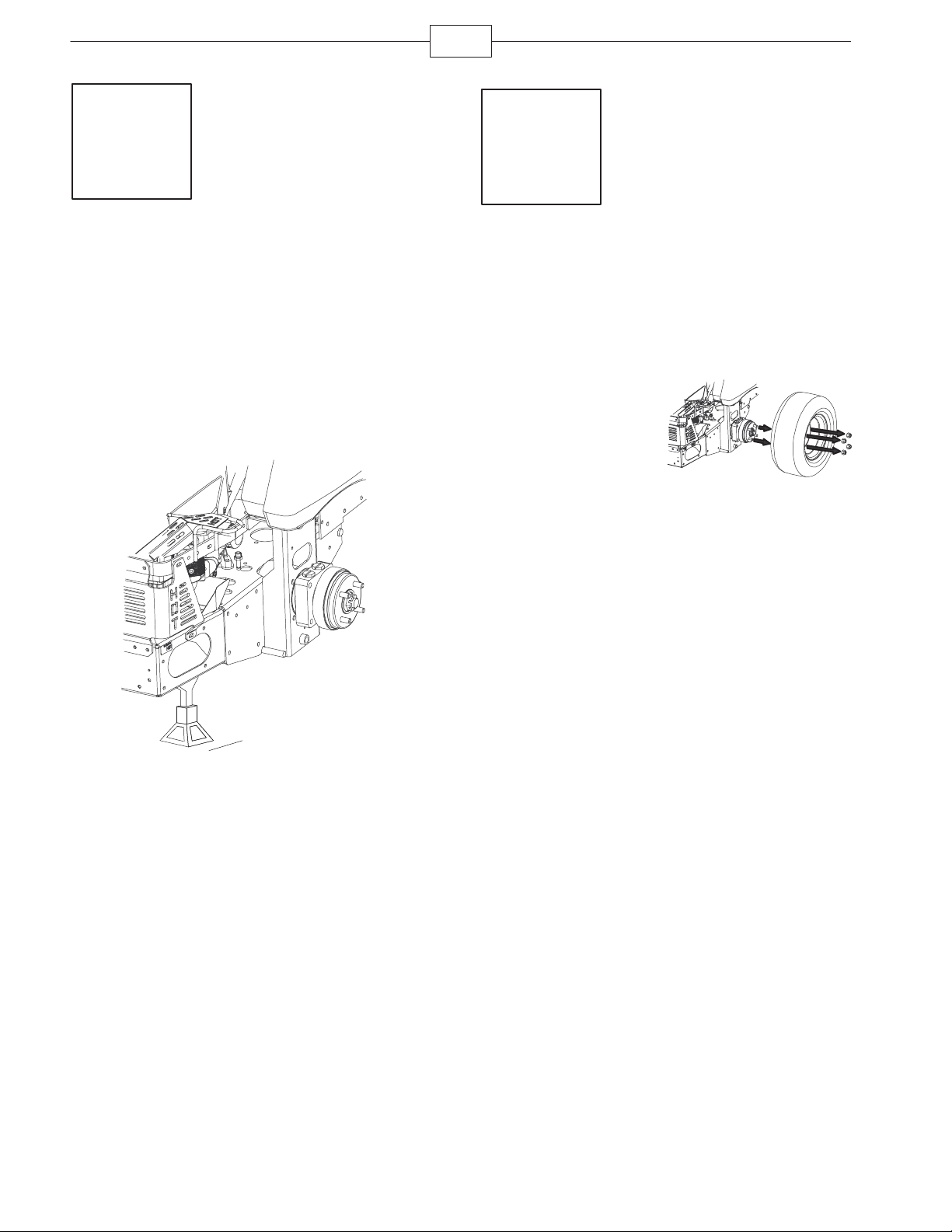
Raising the Machine Up
Parts needed for this step:
None
Procedure
1. Loosen the wheel nuts from both sides of the
vehicle.
2. Raise the back of the machine up and support it
with jack-stands.
Step
2
Removing the Rear Tires
Parts needed for this step:
None
Procedure
1. Remove the wheel
nuts from both sides of
the vehicle.
2. Remove the rear
wheels.
m–7026
m–6919
Page 3
Step
3
3
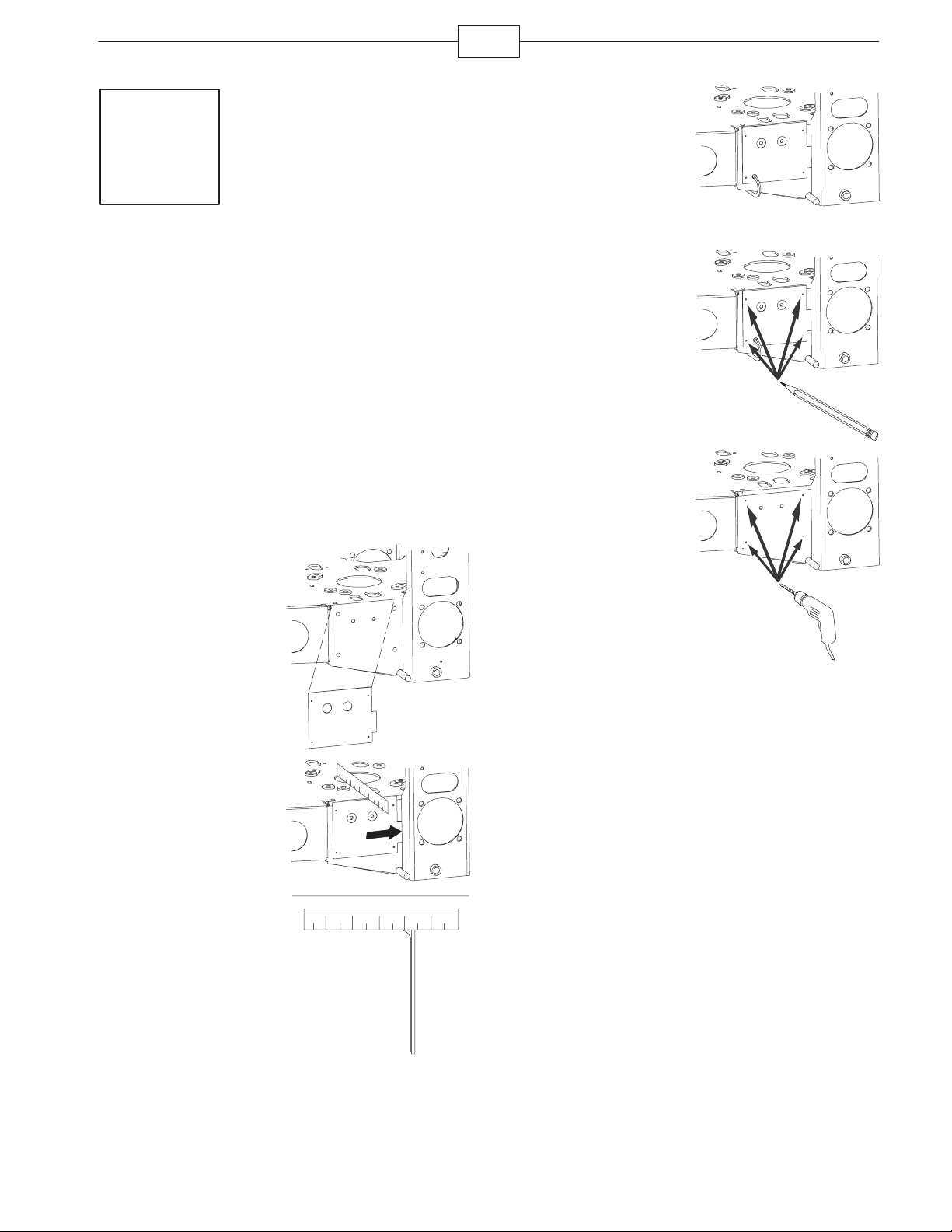
3. Clamp the template
into place.
Drilling Holes for the Roll
Over Protection System
(ROPS)
Note: If you are replacing an existing ROPS, this step
does not need to be performed.
Parts needed for this step:
Qty. Part
1 Template
Procedure
1. Place the template
to the side of the frame.
m–7035
4. Mark and center
punch the holes in the
template.
m–7033
5. Remove the
template and drill
1/8 inch pilot holes in
the marked locations.
6. Drill 13/32 inch
holes through the 1/8
inch pilot holes.
m–7034
7. Repeat this for the opposite side of the frame.
2. Align the template
flush to the top of the
frame and against the
wheel motor frame.
m–7032
m–7031
Page 4

4
Step
4
Removing the Existing Seat
Frame
Parts needed for this step:
None
Procedure
1. Remove the 2 bolts
and 2 locknuts at the
front of the seat where it
is hinged. Save the
hardware.
2. Remove the seat
assembly from the
machine.
5. Install the seat
retaining rod with the nut
and bolt previously
removed.
m–7036
3. Remove the nut and
bolt from the seat
retaining rod.
4. Remove the seat
frame from the existing
seat by removing the
four locknuts. Discard
the seat frame.
m–7021
m–7036
m–7023
Page 5

5
Step
5
Installing the New Seat
Frame
Parts needed for this step:
Qty. Part
1 Seat frame
Procedure
1. Install the seat to
the new seat frame with
the four locknuts
previously removed.
Step
6
Installing the Seat Latch
Catch
Parts needed for this step:
Qty. Part
1 Seat latch catch
2 Bolt, 5/16 x 7/8 inches
2 Locknut, 5/16 inch
m–7022
Procedure
1. Locate the existing holes in the right side of the
frame and drill the holes to 11/32 inch diameter.
2. Install the seat latch catch under the frame with 2
bolts (5/16 x 7/8 inch) and 2 locknuts (5/16 inch).
Note: The bent part of the latch catch should point
downward.
2. Install the seat at
the hinges with the 2
bolts and 2 locknuts
previously removed.
m–7029
m–7027
Page 6

6
Step
7
Installing the Seat Belt
Parts needed for this step:
Qty. Part
2 Seat belt
2 Bolt, 7/16 x 1 inch
2 Locknut, 7/16 inch
Procedure
1. Install the receiver
part of the seat belt
between the cushion
and the metal seat
frame with 1 bolt (7/16 x
1 inch) and 1 locknut
(7/16 inch).
Step
8
Installing the Roll Over
Protection System (ROPS)
Parts needed for this step:
Qty. Part
1 Roll bar, right section
1 Roll bar, left section
1 Roll bar, center section
8 Bolt, 3/8 x 1 inch
8 Curved washer
8 Flange nut, 3/8 inch
2 Bolt, 1/2 x 3-1/4 inches
2 Flange nut, 1/2 inch
2 Lanyard
2. Install the long seat
belt strap between the
cushion and the metal
seat frame with 1 bolt
(7/16 x 1 inch) and
1 locknut (7/16 inch).
m–7024
m–7025
Page 7

7
Procedure
1. Loosely install the right and left roll bar sections
to the frame, using 8 bolts (3/8 x 1 inch), 8 curved
washers, and 8 flange nuts (3/8 inch).
m–6916
3. Lightly oil the ends
of the center roll bar
section.
4. Loosely install the
center roll bar section,
using 2 bolts
(1/2 x 3-1/4 inches) and
2 flange nuts (1/2 inch).
Note: Make sure the
bolts are installed from
the outside of the roll
bar.
Note: Make sure the
lanyard tabs are install
as shown and point
forward.
5. Raise the roll bar
into the upright position
and secure it with the
pins and hairpin cotter
pins fastened to the
lanyards.
6. Torque all lower
fasteners, attached to
the machine frame, to
30 ft–lb.
m–6891
m–6893
2. Install the lanyard
clips onto the 2 bolts
(1/2 x 3-1/4 inches).
Note: Make sure the
bent tab points toward
the head of the bolt.
m–6892
7. Tighten the center
roll bar bolts
(1/2 x 3-1/4 inches) so
the roll bar rotates freely
with some resistance.
Note: No more than one
thread should be
exposed outside the nut.
m–6891
Page 8

8
5
8. Tighten the front
handles against the
center roll bar ends.
Step
m–683
Installing the ROPS Decal on
International Machines Only
1. Install the
international ROPS
decal over the existing
domestic decal on the
inside of the ROPS.
m–7028
Step
10
9
Installing the Decals
Parts needed for this step:
Qty. Part
1 Domestic footrest decal
1 International footrest decal
1 International ROPS decal
Installing the Footrest Decal on
Domestic and International
Machines
1. Install the footrest
decal onto the footrest
as shown.
m–7030
Installing the Drive Wheels
Parts needed for this step:
Qty. Part
2 Rear wheels
Procedure
1. Mount the wheels
with the valve stem to
the outside and secure
them with the nuts
previously removed in
Step 1.
2. Torque the nuts to
95 ft-lb (128 N⋅m).
m–6917
 Loading...