

Page 1

Form No. 3356-419 Rev A
Standard Suspension Seat Kit
For Compact and Mid-Size Z Master® Mowers
Model No. 107–1892
Installation Instructions
Note: Deter mine the left and right sides of the mac hine from the nor mal operating position.
Loose Parts
Use the chart below to verify that all parts have been shipped.
Step
Z100/400 Switch and actuator
assembly
1
2
3
4
Z200/500 Actuator assembly
Bolt, (1/4 x 3/4 inch)
Flange nut, (5/16 inch)
Z100/400 Switch and actuator
assembly
Z200/500 Actuator assembly
Bolt, (1/4 x 3/4 inch)
Flange nut, (5/16 inch)
No parts required
Seat suspension assembly
Bolt, (5/16 x 1 inch)
Washer, (3/8 inch)
Locknut, (5/16 inch)
Seat stop 2
Flange nut, (5/16 inch)
Description
Step
Qty.
1
1
2
2
1
1
2
2
–
1
4
4
4
4
Install the seat switch assembly.
Install the seat switch for an EFI Z
Master.
Remove the seat.
Install the pulley assembly.
spring . It is necessar y to install the seat switc h
assembly included in this kit to ensure the proper
Use
function of the safety interloc k system.
1
Installing the Seat Switch
Assembly
Parts needed for this step:
1
Z100/400 Switch and actuator assembly
1
Z200/500 Actuator assembly
2
Bolt, (1/4 x 3/4 inch)
2
Flange nut, (5/16 inch)
Procedure
Installation of a seat suspension requires a new ,
long er seat switc h actuator that has a strong er
© 2007—The Toro® Company
8111 Lyndale Avenue South
Bloomington, MN 55420
Register at www.Toro.com. Original Instructions (EN)
If safety inter lock s witches ar e disconnected
or dama ged the machine could operate
unexpectedl y causing per sonal injur y .
• Do not tamper with the inter lock
s witches.
• Check the operation of the inter lock
s witches dail y and r eplace an y dama ged
s witches bef or e operating the machine.
1. Stop the engine , w ait for all mo ving par ts to
stop , and remo v e the ignition k ey .
2. Tip the seat forw ard and disconnect the
neg ati v e batter y cable .
Printed in the USA.
All Rights Reserved
Page 2
3. T he switc h is located on the rear frame of the
seat compar tment.
4. Disconnect the electrical wire har ness from the
existing seat switc h assembly b y pulling fir mly
on the connector . Use Figure 1 for Z100/400
series mo w ers and Figure 2 for Z200/500
series mo w ers .
5. R emo v e the seat switc h assembly b y remo ving
the tw o bolts and n uts that secure the switc h
to the frame . R etain the fasteners for later use
( Figure 1 or Figure 2 ).
6. Install the new seat switc h assembly using the
fasteners remo v ed previously .
Note: On the Z200/500 series only the
actuator is re placed and fasteners pro vided in
the assembly can be used ( Figure 2 ).
7. Install the electrical wire har ness connector to
the seat switc h.
Step
2
Installing the Seat Switch
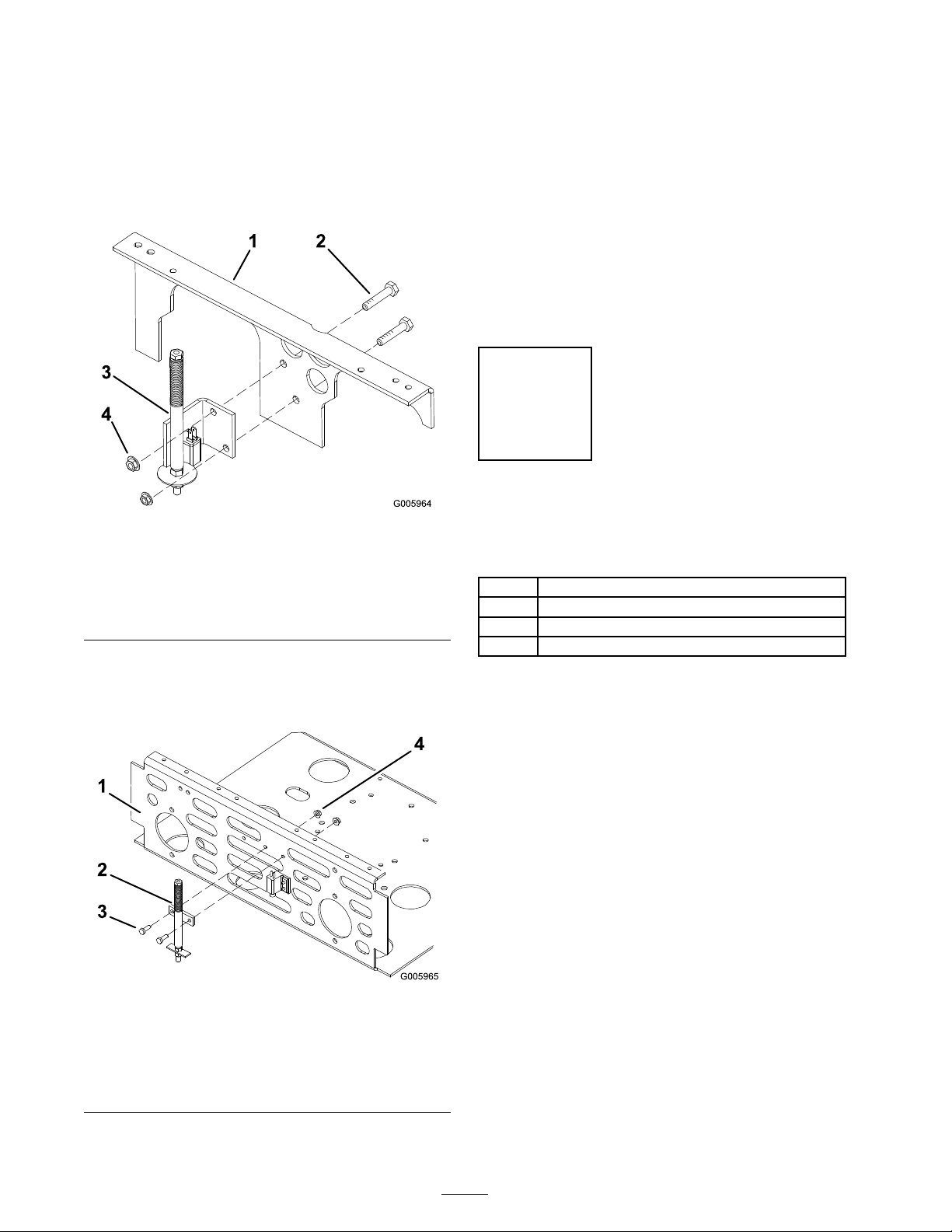
Figure 1
Z100/400 Series Only
1. Frame
2. Switch and catuator
assembly for Z100/400
Series
Note: T he Z100/400 series switc h assembly
v aries from the Z200/500 series actuator
assembly .
for an EFI Z Master
3. Bolt
4. Nut
Parts needed for this step:
1
Z100/400 Switch and actuator assembly
1
Z200/500 Actuator assembly
2
Bolt, (1/4 x 3/4 inch)
2
Flange nut, (5/16 inch)
Procedure
If y ou are re placing a delux e seat with a standard
seat and suspension on a Z Master unit with a
K ohler EFI engine , an actuator assembly and
switc h will not be present. Use the Z100/400
switc h and actuator assembly and the Z200/500
actuator included with this kit to install a new
actuator and switc h.
1. Stop the engine , w ait for all mo ving par ts to
stop , and remo v e the ignition k ey .
2. Tip the seat forw ard and disconnect the
neg ati v e batter y cable .
1. Frame
2. Switch and catuator
assembly for Z200/500
Series
Figure 2
Z200/500 Series Only
3. Disconnect the electrical wire har ness from the
operator presence switc h in the seat b y pulling
fir mly on the connector .
3. Bolt
4. Nut
4. R emo v e the switc h from Z100/400 actuator
and switc h assembly . R emo v e the tw o screws
and tapped plate to se parate the switc h from
the assembly ( Figure 3 ).
2
Page 3
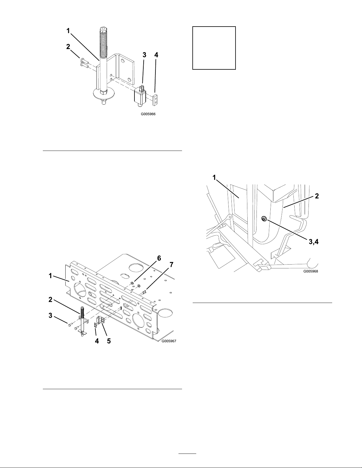
Figure 3
1. Atuator assembly for
Z100/400 Series
2. Screw
3. Switch
4. Tapped plate
5. Using the screws and the tapped plate , attac h
the switc h to the v er tical frame panel at the
rear of the compar tment under the seat as
sho wn in Figure 4 .
Unlatc h and remo v e the right belt co v er . Sa v e
this hardw are .
Step
3
Removing the Seat
No Parts Required
Procedure
Note: Clean the area around the right, rear
anti-scalp wheel.
1. Tip the seat forw ard and remo v e the tw o bolts
and w ashers holding the seat cushion to the
seat pan ( Figure 5 ). R etain the seat cushion
fasteners for later use .
6. Attac h the Z200/500 actuator assembly to
the v er tical frame panel at the rear of the
compar tment under the seat ( Figure 4 ) using
the tw o bolts (1/4 x 3/4 inc h) and tw o flang e
n uts (1/4 inc h) included in the assembly .
Figure 4
1. Frame
2. Z200/500 actuator
assembly
3. Bolt, (1/4 x 3/4 inch)
4. Tapped plate
5. Switch
6. Flange nuts, (1/4 inch)
7. Screws
Figure 5
1. Seat cushion 3. Bolt, left and right side
2. Seat pan
4. Washer, left and right side
2. R emo v e the seat cushion and tip the seat bac k
do wn.
3. R emo v e the n uts holding seat pan to the seat
trac ks ( Figure 6 ). R emo v e the seat and set
aside . R etain the seat pan fasteners for later
use . Discard the conical spacers .
7. Install the wire har ness connector to the
switc h.
3
Page 4

Figure 6
1. Seat pan
2. Flange nuts
4. R emo v e the n uts holding the seat trac k to the
seat mounting frame . R etain the seat trac ks
and fasteners for later use ( Figure 7 ).
Step
4
Installing the Suspension
and Seat
Parts needed for this step:
1
Seat suspension assembly
4
Bolt, (5/16 x 1 inch)
4
Washer, (3/8 inch)
4
Locknut, (5/16 inch)
2 Seat stop
4
Flange nut, (5/16 inch)
Procedure
1. Place the seat stops on the seat mounting
frame so that the bent ends are facing up and
the slots are forw ard ( Figure 8 ).
2. Install the seat trac ks onto the seat stops and
mounting frame ( Figure 8 ).
Figure 7
1. Flange nuts 3. Seat mounting frame
2. Seat track
Note: Mak e sure the seat trac k with the
adjustment lev er is on the right side of the seat.
3. Use the four flang e n uts remo v ed previously to
secure the trac ks and stops to the seat frame .
4. Tip the seat frame do wn.
Note: If the pulley does not tur n, loosen
the bolts to raise the bolt heads and allo w the
pulley to loc k into position.
5. P osition the seat suspension assembly with the
front holes onto the studs in the seat trac ks and
the w eight adjustment knob facing the front
( Figure 8 ). Use the four flang e n uts remo v ed
previously to secure the seat suspension to the
trac ks . Note: If the seat suspension has tw o
sets of mounting holes , use the outside set of
mounting holes .
6. Install the seat pan to the seat suspension with
four bolts (5/16 x 1 inc h), four w ashers (3/8
inc h), and four loc k n uts (5/16 inc h) included
in the suspension assembly .
7. Tilt the seat frame and suspension up .
8. Install the seat cushion to the seat pan using the
existing bolts and w ashers remo v ed previously .
9. After the suspension and seat are installed,
c hec k for proper adjustment of the seat switc h
4
Page 5

actuator rod length. See Adjusting the Seat
Actuator .
1. Pull the suspension adjustment knob out
(forw ard) to adjust the seat.
2. T ur n the knob in the direction indicated on the
label to ac hiev e the desired lev el of suspension.
Note: Initially adjust the setting so that the
seat barely mo v es when the operator slo wly
sits do wn.
3. Push the knob bac k in (rearw ard) when
adjustment is completed.
Adjusting the Seat Actuator
If necessar y , adjust the length of the seat actuator
rod so that the safety interloc k system functions
properly . T he mac hine , with the brak e diseng ag ed
or the PTO eng ag ed, should shut off when the
operator rises of the seat, but will contin ue to r un
when the operator shifts their w eight while in the
seat.
1. Tip the seat forw ard to access the seat switc h
and actuator .
Figure 8
1. Seat cushion 7. Seat tracks
2. Seat pan
3. Flange nut, (5/16 inch)
4. Suspension
5. Washer, (3/8 inch)
6. Bolts, (5/16 x 1 inch)
Operation
Adjusting the Suspension
2. Loosen the bottom loc k n ut of the actuator
rod.
3. Loosen the top n ut and mo v e the w asher/plate
to the desired position.
4. Tighten the n uts .
5. T est the seat to ensure the safety system
functions properly .
Note: R e peat the adjustment procedure if
necessar y .
8. Adjustment lever
9. Seat stops
10. Seat frame
11. Slot
Seat
T here are appro ximately 40 rev olutions needed
to c hang e the suspension setting from the softest
to the most stiff setting .
5
Page 6

Page 7

Page 8

 Loading...