

Page 1
DeluxeSuspensionSeatKit
Z100,Z200,Z400andZ500SeriesZMaster
ModelNo.78530or107–1891
Installation
LooseParts
Usethechartbelowtoverifythatallpartshavebeenshipped.
FormNo.3365-958RevA
®
Mowers
InstallationInstructions
ProcedureDescription
1
2
3
4
5
6
1
RemovingtheSeat
Qty.
Nopartsrequired
Bolt(7/16x1inch)
Deluxesuspensionseat1
Spacer(2holesforZ200/Z500Series)
Spacer(3holesforZ100/Z400Series)
Wireharness1
Plasticties
Nopartsrequired
Decal1Installthedecal.
–
2Installtheseatbelt.
2
2
5
–
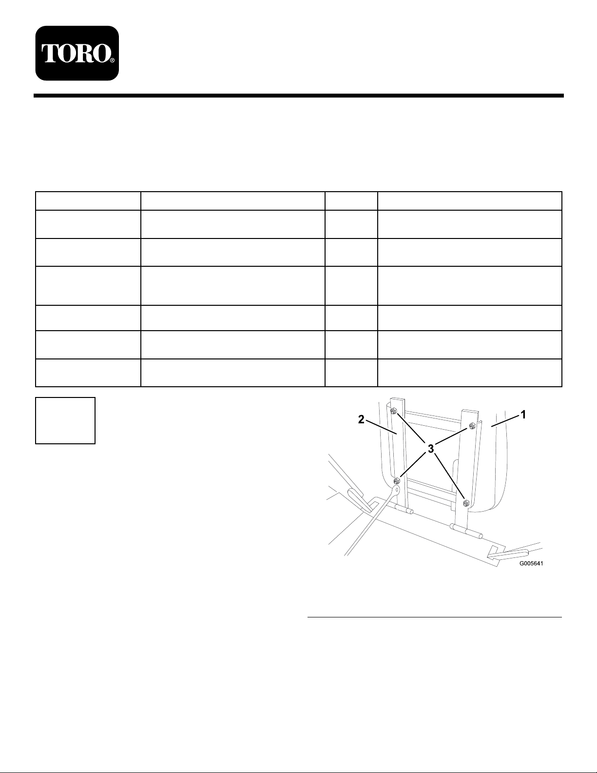
Removetheseat.
Installtheseat.
Installthewireharness.
Testthesafetyinterlocksystem.
Use
NoPartsRequired
Procedure
1.Unlatchtheseatandtiptheseatforward.
2.Removethenutsholdingtheseattothemounting
frame(
3.Removetheseatfromtheframeandsetitaside.
©2010—TheT oro®Company
8111LyndaleAvenueSouth
Bloomington,MN55420
Figure1).Retainthenuts.
Registeratwww.Toro.com.
1.Seat
2.Seatframe
Figure1
3.Nut
OriginalInstructions(EN)
PrintedintheUSA.
AllRightsReserved
Page 2
2
InstallingtheSeatBelt
Partsneededforthisprocedure:
2
Bolt(7/16x1inch)
Procedure
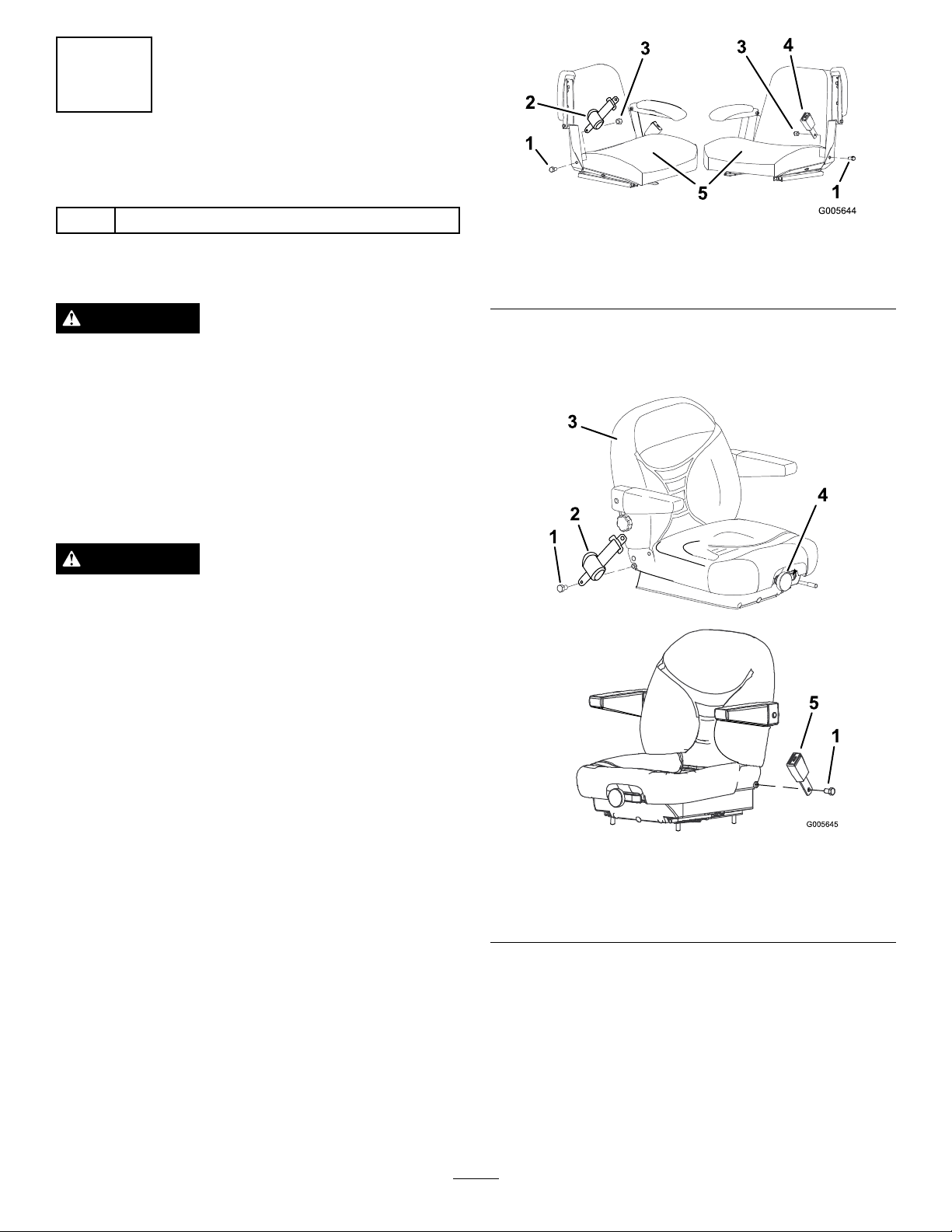
Figure2
1.Bolt
2.Seatbeltretractor5.Seat
3.Nut
4.Seatbeltreceiver
WARNING
Seriousinjuryordeathcanhappenwhentheseat
beltisusedwithoutarollbarinstalled.
Donotinstalltheseatbeltwithoutarollbar
installed.
Ifyoudonothavearollbar,contactanAuthorized
ServicedealertoobtainthecorrectRollOver
ProtectionSystem(ROPS).
WARNING
Toavoidinjuryordeathfromrollover:keepthe
rollbarintheraisedlockedpositionandusethe
seatbelt.
Ensurethattherearpartoftheseatissecuredwith
theseatlatch.
Thedeluxesuspensionseatdoesnotcomeequipped
withseatbeltrestraints.Ifyouareinstallingthe
deluxeseatonamachinewithaRollOverProtection
System(ROPS),theexistingseatbeltrestraintsmustbe
transferredfromtheoldseat.
2.Installtheseatbeltretractorandreceivertothe
deluxeseatusingthe2bolts(7/16x1inch)(Figure5
&Figure3).
Donotinstallandusetheseatbeltwithoutarollbar
installed.ContactanAuthorizedServicedealertoobtain
thecorrectRollOverProtectionSystem(ROPS).
1.Removetheseatbeltretractorandreceiverfromthe
standardseatbyremovingthenutandboltsecuring
thebeltassembliestotheseat(
Figure2).
Figure3
1.Bolt,(7/16x1inch)4.Suspensionadjustment
knob
2.Seatbeltretractor5.Seatbeltreceiver
3.Seat
2
Page 3
3
InstallingtheSeat
Partsneededforthisprocedure:
1Deluxesuspensionseat
2
Spacer(2holesforZ200/Z500Series)
2
Spacer(3holesforZ100/Z400Series)
Procedure
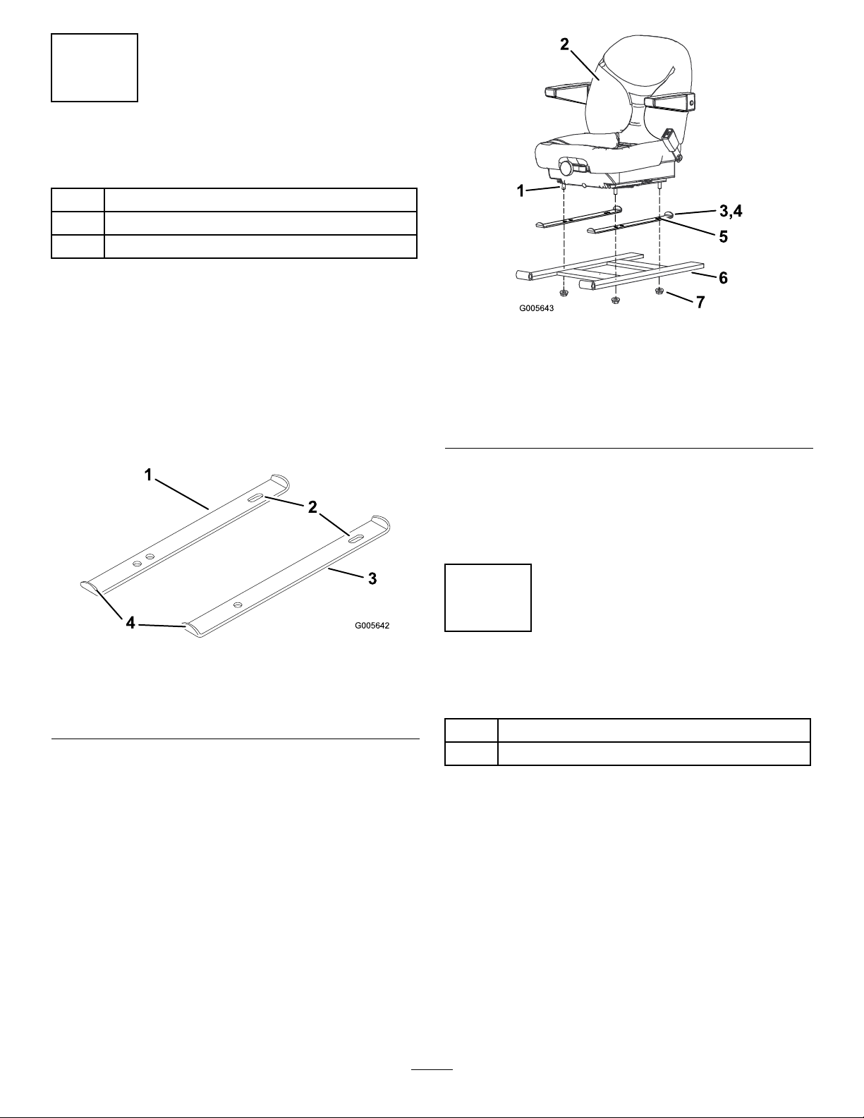
1.Placethespacersontheseatmountingframewith
thebentendsfacingup.Theslotinthespaceris
installedtothebackoftheseat(Figure4).
Note:ZMaster100or400Seriesmodelsare
installedwithspacersthathave3holes.ZMaster
200or500Seriesmodelsareinstalledwithspacers
thathave2holes(
1.Spacer—3holesforZ100
orZ400seriesmodels
2.Slot—installtobackof
seat
2.Removethepackingcoversguardingtheseattrack
studs.
Figure4).
Figure4
3.Spacer—2holesforZ200
orZ500seriesmodels
4.Bentends
Figure5
1.Seattrackstuds5.Slot
2.Seat6.Seatmountingframe
3.Spacer(2holesforZ200
orZ500seriesshown)
4.Spacer(3holesforZ100
orZ400seriesmodels)
Note:Iftheseatmountingframehastwosetsof
mountingholes,usethefrontsetofmountingholes.
4.Securetheseattotheseattrackswiththenuts
removedpreviously(Figure5).
7.Nut
4
InstallingtheWireHarness
Partsneededforthisprocedure:
1Wireharness
5
Plasticties
3.Positionthenewseatwiththeseattrackstudsinthe
spacersandseatmountingframe(
Figure5).
Procedure
1.Locateanddisconnectthewireharnessconnectors
thatareattachedtooldseatswitch(Figure7).
Note:Ensuretheoldswitchisremovedfromthe
machine.
2.Removetheexistingseatswitch,bolt,spring,switch
bracket,andnuts(
3
Figure7).
Page 4

WARNING
G013786
1 2
3
Ifthesafetyinterlockswitchesareboth
connectedthemachinecouldoperate
unexpectedlycausingpersonalinjury.
•Ensuretheoldswitchisremovedfromthe
machine.
•Ensurethenewharnessisconnectedtothe
newseatswitchintheseat.
•Checktheoperationoftheinterlockswitches
dailyandreplaceanydamagedswitches
beforeoperatingthemachine.
3.Ifyourmachinehasasingleconnectorfromthe
oldswitch,removetheplastictieholdingthewire
harnesstotheframeneartheseatswitch(Figure7).
Reconnecttheotherexistingwirestomachineframe.
4.Plugthesingleconnectorendofthenewwire
harnessintotheconnectorthatwasremovedfrom
theoldseatswitch(
5.Ifyourmachinehastwoleadsfromtheoldswitch,
foldoverthewireleadsandsecurethemwitha
plastictiecable(Figure6).Donotusethesewire
leads.
6.Ifyourmachinehastwoleadsfromtheoldswitch,
locatethesingleconnectorinthemainharnessnear
thecontrolpanel.Plugthenewharnessintothe
singleconnectorfromthemainharness(
Figure7).
Figure6).
Kubotapoweredmachineshown
1.Plastictiecable
2.Twowireleadsfromthe
oldswitch
Figure6
3.Singleconnectorfrom
mainharness(only
onmachineswithtwo
connectorsfromold
switch).
7.Positionthewireharnessalongtheseathold-uprod,
overtotheseatmountingframeanduptothenew
switch,locatedunderseat(
Figure7).
8.Attachthetwoconnectorsofthenewwireharness
intothenewseatswitch(Figure7).
9.Moveseattothefurthestrearposition.Usethethree
plastictiestoattachthewireharnesstoseatholdup
rodandseatmountingframe(
Figure7).
10.Carefullylowertheseatdownandensuretheharness
doesnotgetpinched.Ifitdoes,repositionthe
plasticties.
4
Page 5

G013785
9
11
12
13
14
15
5
TestingtheSafetyInterlock
System
NoPartsRequired
Procedure
WARNING
Ifsafetyinterlockswitchesaredisconnectedor
damagedthemachinecouldoperateunexpectedly
causingpersonalinjury.
•Donottamperwiththeinterlockswitches.
•Checktheoperationoftheinterlockswitches
dailyandreplaceanydamagedswitchesbefore
operatingthemachine.
Thesafetyinterlocksystemisdesignedtopreventthe
enginefromstartingunless:
Figure7
1.Removeexistingplastic
tieandreplacewhendone
2.Seathold-uprod10.Seatmountingframe
3.Singleconnectorfromold
seatswitch
4.Singleconnectoronnew
harness
5.Plasticties
6.Newwireharness14.Nuts
7.Newseatswitch
8.Twoconnectorsfromnew
harness
9.Oldseatswitchbracket
assembly
11.Bolt
12.Spring
13.Switchbracket
15.Oldseatswitch(remove)
•Theparkingbrakeisengaged.
•Thepowertakeoff(PTO)isdisengaged.
•Themotioncontrolleversareintheneutrallocked
position.
Thesafetyinterlocksystemalsoisdesignedtostopthe
enginewhenthetractioncontrolsaremovedfromthe
lockedpositionwiththeparkingbrakeengagedorifyou
risefromtheseatwhenthePTOisengaged.
Testthesafetyinterlocksystembeforeyouusethe
machineeachtime.Ifthesafetysystemdoesnotoperate
asdescribedbelow,haveanAuthorizedServiceDealer
repairthesafetysystemimmediately.
1.Sittingontheseat,engagetheparkingbrakeand
movethePTOtoon.Trystartingtheengine;the
engineshouldnotcrank.
2.Sittingontheseat,engagetheparkingbrakeand
movethePTOtooff.Moveeithermotioncontrol
lever(outofneutrallockedposition).Trystarting
theengine;theengineshouldnotcrank.Repeatfor
othercontrollever.
3.Sittingontheseat,engagetheparkingbrake,move
thePTOswitchtooffandmovethemotioncontrol
leverstoneutrallockposition.Nowstarttheengine.
Whiletheengineisrunning,releasetheparking
brake,engagethePTOandriseslightlyfromthe
seat;theengineshouldstop.
4.Sittingontheseat,engagetheparkingbrake,move
thePTOswitchtooffandmovethemotioncontrol
5
Page 6

leverstoneutrallockposition.Nowstarttheengine.
Whiletheengineisrunning,centereithermotion
controlandmove(forwardorreverse);theengine
shouldstop.Repeatforothermotioncontrol.
Operation
AdjustingtheSuspension
5.Sittingontheseat,disengagetheparkingbrake,
movethePTOswitchtooffandmovethemotion
controlleverstoneutrallockposition.Trystarting
theengine;theengineshouldnotcrank.
6
InstallingtheDecal
Partsneededforthisprocedure:
1Decal
Procedure
Removethebackingoffthedecalandplacethedecalon
thebackoftheseatasshowninFigure8.
Seat
Usetheadjustmentknobandweightgaugelocatedin
thefrontoftheseattoadjusttheseatsuspensiontothe
weightoftheoperator
Figure3.
1.Backofseat
Figure8
2.Decal
6
Page 7

Notes:
7
Page 8

 Loading...