

Page 1

Form No. 3350-454
Roll Over Protection System Kit
200 and 500 Series Z Masters
Part No. 107–0038
Installation Instructions
Note: This kit is used for replacing an existing ROPS or adding it to a machine without an existing ROPS.
Loose Parts
Note: Use the chart below to identify parts for assembly.
Step Description Qty. Use
1
2
3
4
5
No parts needed – Removing the drive wheels
Roll bar, right section
Roll bar, left section
Roll bar, center section
Bolt, 3/8 x 1 inch
Bolt, 3/8 x 1–1/2 inch
Curved washer, 3/8 inch
Flange nut, 3/8 inch
Locknut, 3/8 inch
Internal lock washer
Bolt, 1/2 x 3-1/4 inches
Flange nut, 1/2 inch
Lanyard
No parts needed – Installing the drive wheels
No parts needed – Removing the existing seat frame
Seat frame 1 Installing the new seat frame
1
1
1
4
2
6
6
2
2
2
2
2
Installing the roll over protection system
(ROPS)
Seat latch catch
6
7
8
9
2003—The Toro Company
8111 Lyndale A ve., Blomington, MN 55420, USA
Bolt, 5/16 x 3/4 inch
Locknut, 5/16 inch
Template 1
Seat latch catch
Side locknut, 5/16 inch
Serrated locknut, 5/16 inch
Seat belt
Bolt, 7/16 x 1 inch
Locknut, 7/16 inch
1
2
2
1
2
2
1
2
2
Printed in the USA
All Rights Reserved
Installing a seat latch catch on 500 Series
machines
Drilling holes for a seat latch catch on 200
Series Machines
Installing a seat latch catch on 200 Series
machines
Installing the seat belt on a standard seat
Original Instructions (EN)
Register your product at www.Toro.com
Page 2

Step UseQty.Description
2
10
11
Seat belt
Bolt, 7/16 x 1 inch
Washer, 7/16 inch
Footrest decal 1 Installing the Decals
1
2
2
Installing the seat belt on a deluxe seat
Page 3
3
Step
1
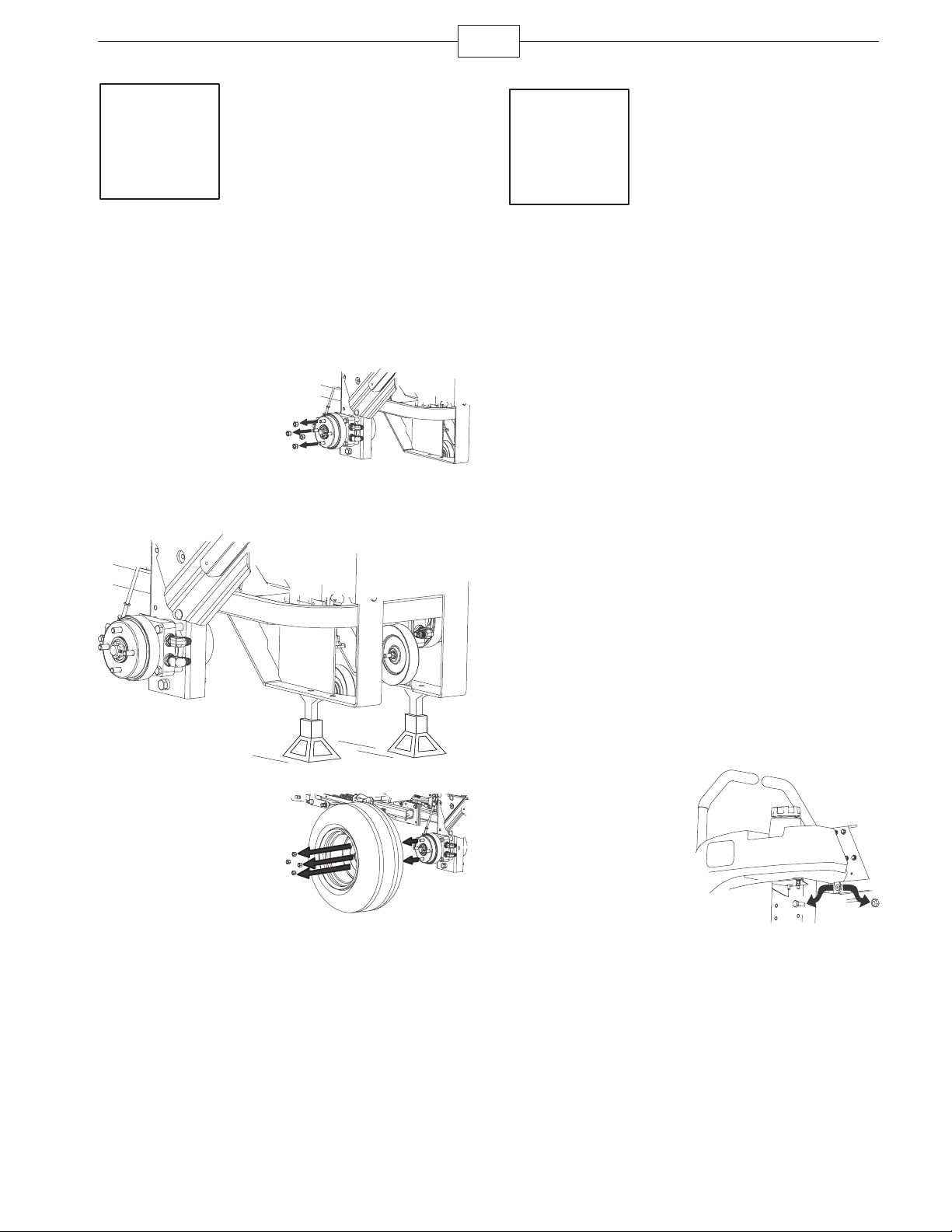
Removing the Drive Wheels
Parts needed for this step:
None
Procedure
1. Loosen the wheel
nuts or bolts on both
sides of the machine.
m–6858
2. Raise the back of the machine up and support it
with jack-stands.
Step
2
Installing the Roll Over
Protection System (ROPS)
Note: When installing the ROPS with a previously
installed bagger, contact an Authorize Service Dealer
for the correct procedure.
Parts needed for this step:
Qty. Part
1 Roll bar, right section
1 Roll bar, left section
1 Roll bar, center section
2 Bolt, 3/8 x 4–1/2 inches
2 Bolt, 3/8 x 1–1/2 inch
2 Lock nut, 3/8 inch
2 Internal lock washer, 3/8 inch
4 Bolt, 3/8 x 1 inch
6 Curved washer
6 Flange nut, 3/8 inch
2 Bolt, 1/2 x 3-1/4 inches
2 Flange nut, 1/2 inch
3. Remove the wheel
nuts on both sides of the
machine.
4. Remove the drive
wheels from the
machine.
m–6859
Procedure
1. Remove and discard
the fuel tank mounting
bolt and nut from under
the tank on each side.
m–6857
Page 4
4
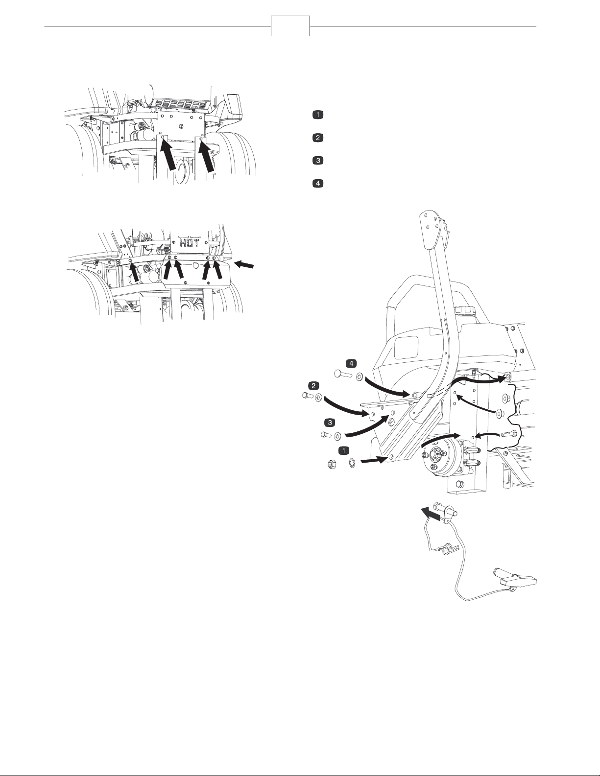
2. For an air cooled machine, loosen the two bottom
bolts in the rear bumper.
m–6886
3. For a liquid cooled machine, loosen the two side
and four back bolts in the rear bumper.
m–6885
4. Install the bolts in the order shown in the figure
below.
5. Loosely install the right and left roll bar sections
to the frame, in numbered order as follows:
Lock nut (3/8 inch), internal tooth lock washer, and
Bolt (3/8 x 1–1/2 inch)
Bolt (3/8 x 1 inch), curved washer, and flange nut
(3/8 inch)
Bolt (3/8 x 1 inch), curved washer, and flange nut
(3/8 inch)
Bolt (3/8 x 4-1/2 inches), curved washer, and
flange nut (3/8 inch)
m–7125
6. Install the lanyard
clips onto the 2 bolts
(1/2 x 3-1/4 inches).
Note: Make sure the
bent tab points toward
the head of the bolt.
m–6892
Page 5

5
5
7. Lightly oil the ends
of the center roll bar
section.
8. Loosely install the
center roll bar section,
using 2 bolts
(1/2 x 3-1/4 inches) and
2 flange nuts (1/2 inch).
Note: Make sure the
bolts are installed on the
outside of the roll bar.
Note: Make sure the
lanyard tab is installed
as shown and points
forward.
9. Raise the roll bar
into the upright position
and secure it with the
pins and hairpin cotter
pins fastened to the
lanyards.
m–6891
m–6893
12. Tighten the front
handles against the
center roll bar ends.
13. Tighten the rear
bumper bolts.
m–683
Step
10. Tighten the center
roll bar bolts
(1/2 x 3-1/4 inches) so it
rotates freely with some
resistance.
Note: No more than one
thread should be
exposed outside the nut.
11. Torque all lower
fasteners, attached to
the machine frame, to
30 ft–lb.
m–6891
3
Installing the Drive Wheels
Parts needed for this step:
Qty. Part
2 Rear wheels
Procedure
1. Mount the wheels
with the valve stem to
the outside and secure
them with the nuts or
bolts previously
removed in Step 1.
2. Torque the nuts or
bolts to 95 ft-lb
(128 N⋅m).
m–6859
Page 6

6
Step
4
Removing the Existing Seat
Frame
Parts needed for this step:
Qty. Part
1 Seat
4 Flange nuts (installed on the seat)
Procedure
Note: Standard seat is shown in the following two
diagrams.
1. Remove the 2 bolts
and 2 locknuts at the
front of the seat where it
is hinged. Save the
hardware.
2. Remove the seat
assembly from the
machine.
Steps needed for a Deluxe Seat
1. Remove the two connectors from the seat switch.
2. Remove the cable ties from the seat frame.
m–6877
3. Remove the seat
frame from the existing
seat by removing the
four locknuts. Discard
the seat frame.
4. Remove the nut and
bolt from the seat
retaining rod.
m–7021
m–7023
m–7108
Page 7

Step
5
Installing the New Seat
Frame
Parts needed for this step:
Qty. Part
1 Seat frame
Procedure
Note: Standard seat shown only.
1. Install the seat to
the new seat frame with
the four locknuts
previously removed.
7
3. Install the seat
retaining rod with the nut
and bolt previously
removed.
Note: Do not over
tighten the nut and bolt
to allow the retaining rod
to pivot.
m–7108
4. If needed, attach the two connectors onto the
seat switch.
m–7022
2. Install the seat at
the hinges with the 2
bolts and 2 locknuts
previously removed.
m–6877
m–7029
Page 8

8
Step
6
Replacing a Seat Latch
Catch on 500 Series
Machines
Parts needed for this step:
Qty. Part
1 Seat latch catch
2 Bolt, 5/16 x 3/4 inches
2 Locknut, 5/16 inch
Procedure
1. Remove the existing latch catch.
2. Install the new seat latch catch to the frame with
2 bolts (5/16 x 3/4 inch) and 2 locknuts (5/16 inch).
Note: The bent part of the latch catch needs to point
downward.
Step
7
Drilling Holes for a Seat
Latch Catch on 200 Series
Machines
Parts needed for this step:
Qty. Part
1 Template
Procedure
1. Position the template, by locating it with the
second existing hole from the right side of the frame.
The existing hole is on the top of the frame.
m–7103
m–7101
2. Mark the holes in the template and drill two holes
(11/32 inch diameter) into the side of the frame.
m–7102
Page 9

Step
8
Installing the Seat Latch
Catch for 200 Series
Machines
Parts needed for this step:
Qty. Part
1 Seat latch catch
2 Side locknut, 5/16 inch
2 Serrated locknut, 5/16 inch
Procedure
The diagram to the right
shows a serrated
locknut. Notice the
grooves on the flange
side of the nut.
9
2. Install the new seat latch catch and serrated
locknuts to the frame with 2 side locknuts (5/16 inch).
Torque the side locknuts to 33 ft–lb.
m–7104
3. Ensure the seat latch catch is installed 5/8 inches
(16 mm) from the frame as shown below. If it is not
correct, adjust the nuts to achieve this dimension.
Side View
m–7111
The diagram to the right
shows a side locknut.
Notice the dimples in the
side of the nut.
m–7111
1. Install the serrated locknuts onto the seat latch
catch as far as they can go on by hand.
Note: The 200 Series seat latch catch is shown
below.
m–7111
m–7116
Page 10

10
Step
9
Installing the Seat Belt on a
Standard Seat
Parts needed for this step:
Qty. Part
1 Seat belt
2 Bolt, 7/16 x 1 inch
2 Locknut, 7/16 inch
Procedure
1. Install the receiver
part of the seat belt
between the cushion
and the metal seat
frame with 1 bolt (7/16 x
1 inch) and 1 locknut
(7/16 inch).
Step
10
Installing the Seat Belt on a
Deluxe Seat
Parts needed for this step:
Qty. Part
1 Seat belt
2 Bolt, 7/16 x 1 inch
2 Washer, 7/16 inch
Procedure
1. Install the receiver
part of the seat belt to
the outside of the metal
seat frame with 1 bolt
(7/16 x 1 inch) and
1 washer (7/16 inch).
m–7109
2. Install the long seat
belt strap between the
cushion and the metal
seat frame with 1 bolt
(7/16 x 1 inch) and
1 locknut (7/16 inch).
m–7024
m–7025
2. Install the long seat
belt strap to the outside
of the metal seat frame
with 1 bolt (7/16 x
1 inch) and 1 washer
(7/16 inch).
m–7110
Page 11

Step
11
Installing the Decals
Parts needed for this step:
Qty. Part
1 Footrest decal
Installing the Footrest Decal
1. Install the footrest
decal onto the footrest
as shown.
m–7030
11
Page 12

12
 Loading...