

Page 1

36/42” Rear Discharge Mower Conversion Kit
42/48” Side Discharge Mower Conversion Kit
XT Series Garden Tractors
Part No. 106–8252
Part No. 106–8253
Installation Instructions
Note: Determine the left and right sides of the machine from the normal operating position.
Loose Parts
Note: Use the chart below to identify parts used for assembly.
Description Qty. Use
Form No. 3329–500
Mower bracket–L.H.
Mower bracket–R.H.
Carriage bolt–3/8 x 1 inch
Lock nut–3/8
Carriage bolt–7/16 x 1–1/2 inch
Spacer–11/16 inch long
Lock nut–7/16
Draft bar assembly–L.H.
Draft bar assembly–R.H.
Hitch assembly
Washer–5/8 x 1 inch
Cotter pin–1/8 x 1–1/2 inch
Bolt–3/8 x 1–1/4 inch
Spacer–5/16 inch long
Flange nut
Adjusting rod
Lift trunnion
Lock nut–3/8 inch
Washer–3/8 x 13/16 inch
Washer–3/8 x 13/16 inch
(Use on Side Discharge Mowers only)
Cotter pin–3/32 x 1–3/4 inch
1
1
4
4
2
2
2
1
1
1
4
2
4
4
4
1
1
1
1
1
2
Installing the new mower suspension
Pulley box assembly 1 Installing the pulley box to tractor
PTO belt–46 in. length 1 Mount to tractor and pulley box
Drive belt–69 in. length 1 Use with 42” and 48” Side Discharge Mowers
Drive belt–63.88 in. length 1 Use with 42” Rear Discharge Mower
Drive belt–62.75 in. length 1 Use with 36” Rear Discharge Mower
2003 by The Toro Company
8111 Lyndale Avenue South
Bloomington, MN 55420-1196
1
All Rights Reserved
Printed in the USA
Page 2
Preliminary Preparation
Installing the New Mower
1. Park the tractor and mower on a level surface,
disengage the blade control (PTO), set the parking
brake, stop the engine, and remove the ignition key.
2. Lower the mower to its lowest position and remove the
mower from the tractor. Refer to the mower Operator’s
Manual for removal instructions.
3. Thoroughly clean the mower. All debris must be
removed to ensure that parts will fit the mower
properly.
Removing the Old Mower
Suspension
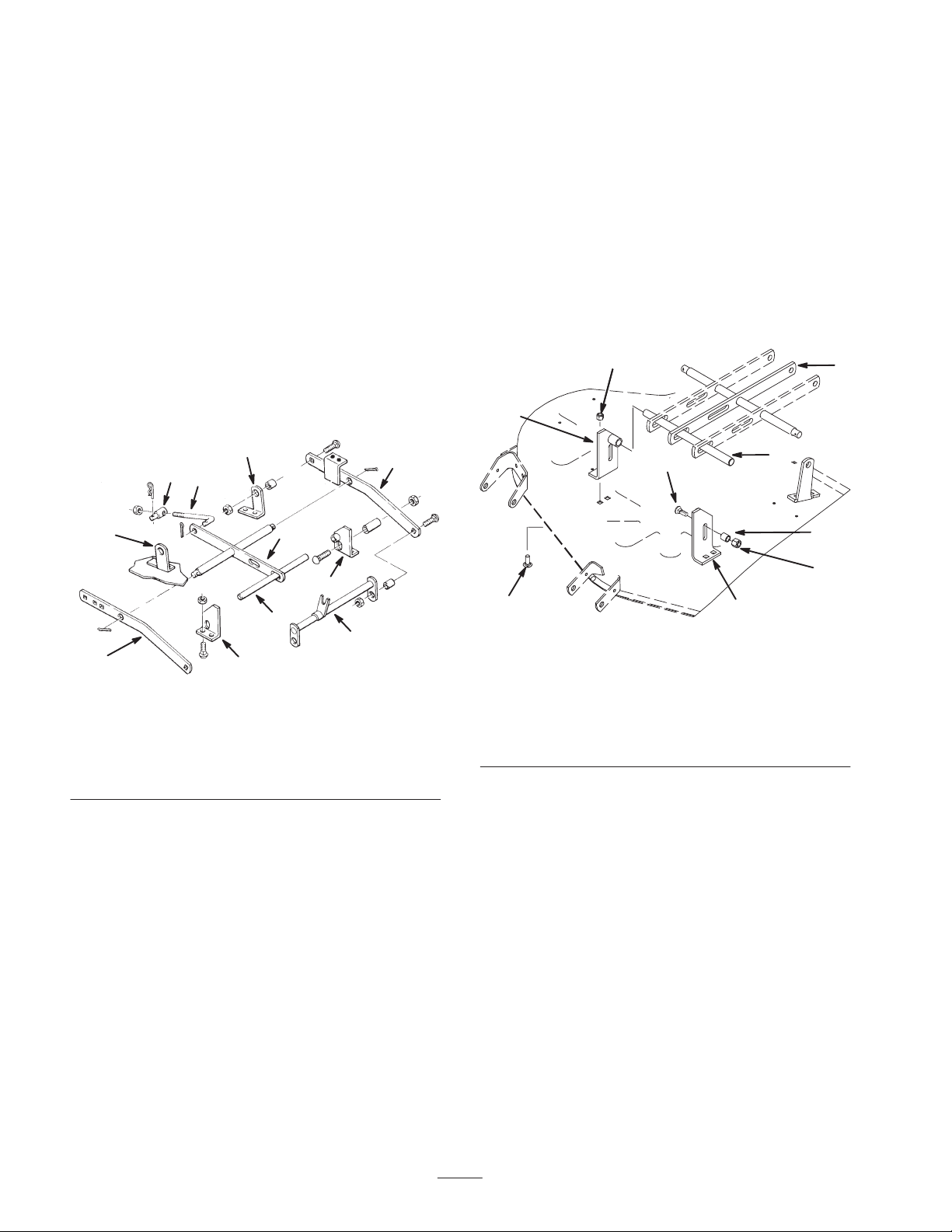
1. Remove the cotter pin securing the adjusting rod
trunnion to the mower bracket (Fig. 1).
7
1
2
7
5
4
6
3
4
Figure 1
1. Adjusting rod
2. Adjusting rod trunnion
3. Draft bar
4. Front mower brackets
5. Leveler bar
6. Leveler shaft
7. Rear mower brackets
8. Hitch assembly
2. Remove the carriage bolts, spacers and nuts securing
the draft bars to the rear mower brackets (Fig. 1).
3. Remove the cotter pins securing the draft bars to the
leveler bar (Fig. 1).
4. Remove the carriage bolts and nuts securing the front
mower brackets to the mower (Fig. 1).
5. Remove and retain the leveler shaft and the leveler bar.
Discard all other components (Fig. 1). Do not remove
the rear mower brackets from the mower.
3
8
m–6698
Suspension
1. Make sure the leveler shaft is positioned through the
hole(s) in the leveler bar(s) (Fig. 2).
Note: Some side discharge mowers may be equipped with
one, two or three leveler bars.
2. Insert a new right and left front mower bracket onto the
appropriate end of the leveler shaft. Position the
brackets as shown in figure 2.
Note: On side discharge mowers, the mounting flanges on
the mower bracket face inward.
66
3
7
5
Figure 2
1. Leveler bar
2. Leveler shaft
3. R.H. mower bracket
4. L.H. mower bracket
5. Carriage bolt
(3/8 x 1 inch)
6. Lock nut (3/8 inch)
7. Carriage bolt (7/16 x
1–1/2 inch
8. Spacer (11/1‘6 inch long)
9. Lock nut (7/16 inch)
3. Using the old bracket mounting holes, mount each
mower bracket to the mower with 2 carriage bolts
(3/8 x 1 inch) and locknuts (3/8 inch) (Fig. 2).
Note: The carriage bolt heads are to be positioned under
the mower.
4. Loosely mount a carriage bolt (7/16 x 1–1/2 inch),
spacer (11/16 inch long) and flange lock nut (7/16 inch)
to each front mower bracket. Position the components
as shown in figure 2.
2
8
9
4
m–6699
1
2
Page 3
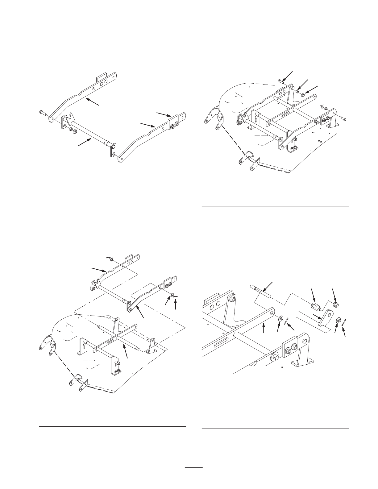
5. Loosely mount a new draft bar assembly to each end of
the hitch assembly with a capscrew (3/8 x 1–1/4 inch),
spacer (5/16 inch long) and lock nut (3/8 inch) (Fig. 3).
Make sure the draft bar bumpers are positioned to the
outside.
7. Secure each draft bar to the rear mower brackets with a
capscrew (3/8 x 1–1/4 inch), spacer (5/16 inch long)
and flange nut (3/8 inch) (Fig. 5). Position the fasteners
as shown in figure 5.
1
2
3
1
3
2
4
m–6700
Figure 3
1. R.H. draft bar assembly
2. L.H. draft bar assembly
3. Bumper
4. Hitch assembly
6. Assemble the draft bars onto the leveler bar (Fig. 4) and
secure each end with a washer (5/8 x 1 inch) and cotter
pin.
Note: The draft bars will rest on the front mower bracket
spacers and positioned to the outside of the rear mower
brackets.
2
m–6701
Figure 5
1. Capscrew
2. Spacer
3. Flange nut (3/8 inch)
8. Assemble the lift trunnion and the lock nut (3/8 inch)
onto the adjusting rod (Fig. 6).
9. Hook the adjusting rod into the leveler bar and secure
with a washer and cotter pin (Fig. 6).
10.Insert the lift trunnion into the mower bracket and
secure it with a washer (3/8 x 13/16 inch) (side
discharge mowers only) and cotter pin (Fig. 6).
1
2 3
1. Leveler bar
2. Draft bar
Figure 4
2
1
3. Washer
4. Cotter pin
3
4
5
4
7
6
8
9
m–6703
Figure 6
m–6702
1. Adjusting rod
2. Lift trunnion
3. Lock nut (3/8 inch)
4. Leveler bar
5. Washer
6. Cotter pin
7. Mower bracket
8. Washer (Side discharge
mowers only)
9. Cotter pin
3
Page 4

Installing the Mower
1. Disengage the PTO and set the parking brake.
2. Stop the engine, remove the key, and wait for all
moving parts to stop before leaving the operating
position.
8. Place the attachment lift pin into the slot in the center
lever bar and secure it with a washer (3/4 inch) and a
hairpin cotter (Fig. 8).
9. Rotate the front mounting shaft so the fork faces
straight up and aligned so the spacers are between the
mid-mount hitch plates (Fig. 9).
3. Position the mower on the right side of the tractor.
4. Turn the front wheels fully to the left and raise
attachment lift lever or electric lift all the way up. Refer
to the tractor Operator’s Manual.
5. Open the mid-mount hitch by pulling out the J–pin and
moving the lock handle rearward (Fig. 7).
1
m–6622
Figure 7
1. Front hitch
2. Mid-mount hitch
3. J–pin
4. Lock handle
5
4
1
4
2
3
1. Front mounting shaft
2. Fork
3. Spacer
Figure 9
4. Mid-mount hitch plate
5. Hitch rod
2
3
3
m–2825
10.Lift the mower with the attachment lift lever or electric
lift and guide the fork to capture the hitch rod (Fig. 9).
11. Close the mid-mount hitch lock handle by rotating it
forward (Fig. 10).
6. Slide the mower under the tractor from the right side
and slide the attachment lift between the center and left
side level bar (Fig. 8).
1
5
6
2
3
4
m–2824
Figure 8
1. Attachment lift
2. Slot in center level bar
3. Washer
4. Hairpin cotter pin
5. Left level bar
6. Right footrest
7. Straighten the front wheels and lower the attachment lift
lever or electric lift to the mounting position; refer to
the tractor Operator’s Manual.
1
m–6622
Figure 10
1. Front hitch
2. Mid-mount hitch
3. J–pin
4. Lock handle
Installing the Front Pulley Box
Install the front pulley box if it is not already installed.
1. Rotate the knobs to adjust the idler pulleys so there is a
1/4 inch (7 mm) clearance between the idler arms and
the mounting pins (Fig. 11).
4
2
3
4
Page 5

3 2
4
2
4
4
7
1
1
8
2
3
3
m–6621
Figure 11
1. Mounting Pins
2. Idler arm
3. 1/4 inch (7 mm) clearance
4. Knob
2. Make sure the front latches are open and then slide the
pulley box into the front hitch.
Note: Make sure the pulley box engages and closes the
latches.
3. Adjust both idler pulleys until they are totally to the
outside by turning the knobs.
4
6
5 1
m–6624
Figure 13
1. Pulley box
2. Upper pulley
3. Upper Idler pulley
4. PTO clutch pulley
5. Right knob
6. Left knob
7. PTO belt
8. Check 1/2 inch deflection
here
Installing the Mower Drive Belt
1. Adjust the mower height–of–cut to the middle position;
refer to the tractor Operator’s Manual.
2. Install the mower drive belt onto the mower center
pulley (Fig. 14). Ensure that it is on the upper center
pulley.
2
3. Install the mower drive belt onto the lower pulley and
the lower idler pulley in the pulley box (Fig. 14).
1
3
m–6620
Figure 12
1. Front hitch
2. Pulley box
3. Knob
4. Idler pulley
Installing the PTO Belt
If desired, remove the hood for better access to the upper
pulleys in the pulley box. Refer to the tractor Operator’s
Manual.
1. Install the PTO belt onto the clutch pulley (Fig. 13).
2. Install the PTO belt onto the upper pulley and upper
idler pulley in the pulley box (Fig. 13).
3. Turn the left (upper) knob on the front pulley box to
tighten the PTO drive belt (Fig. 13). There needs to be a
1/2 inch (13 mm) deflection in the belt.
4. Turn the right (lower) knob on the front pulley box to
tighten the mower drive belt (Fig. 13). There needs to
be a 1/2 inch (13 mm) deflection in the belt.
6
5
4
23
m–6625
Figure 14
1. Pulley box
2. Lower pulley
3. Lower Idler pulley
4. Mower center pulley
5. Mower drive belt
6. Check 1/2 inch deflection
here
1
5
Page 6

Checking the Front-to-Rear
Blade Slope
Check the front-to-rear blade slope any time you install the
mower.
1. Check the tire pressure on the tractor. Refer to the
tractor Operator’s Manual.
2. Position one blade front-to-rear (Fig. 15). Measure at C
and either D location (Fig. 15) from a level surface to
the cutting edge of the blade tips (Fig. 16).
3. The mower blade should be 1/8–1/4 inch (4–7 mm)
lower in front at C than in the rear at D. Rotate the
blades and repeat for the other blades.
4. If it is not correct, proceed to Changing the mower
Front–to–Rear Pitch.
Front
C
1
2
m–3499
Figure 17
1. Adjustable link 2. Locknut
Transport Height Adjustment
Transport height is adjusted to stabilize the mower in the
up, locked position.
1. Raise the mower to the highest height–of–cut and check
if the transport level stops contact the bottom of the
draft bars (Fig. 18).
2. If needed, loosen and adjust the transport level stops so
they just contact the bottom of the draft bars (Fig. 18).
D
D
m–1078
Figure 15
MEASURE FROM
CUTTING EDGE TO A
LEVEL SURFACE
m–2539
Figure 16
Changing the Front-to-Rear
Blade Slope
1. To adjust the front-to rear blade slope turn the locknut
on rear adjustable link (Fig. 17).
Note: To raise the front of the mower, turn locknut
clockwise, to lower front turn counterclockwise.
m–6637
3
1
2
Figure 18
1. Transport level
stop—right side shown
2. Draft bar
3. Right side footrest
3. Raise the attachment lift lever or electric lift all the way
up. Check if bumpers, on rear of mower draft bars
contact under footrests (Fig. 19).
6
Page 7

Replacing the Power Take Off
1
2
4
(PTO) Belt
Warning
3
m–6623
Figure 19
1. Bumper
2. Right rear tire
3. Draft bar
4. Footrest
4. If the bumpers do not contact footrests, adjust the lift
chain by turning the nut on the eyebolt in the rear hole
of tractor lift (Fig. 20). Turn the nut clockwise to raise
the mower or counterclockwise to lower it.
5. If one of the bumpers does not contact the footrest,
adjust the appropriate transport level stop (Fig. 18).
5
2
1
Components around engine will be hot if the
machine has been running. Touching hot
components can cause burns.
• Do not touch the engine components or the
muffler when hot.
• Allow the engine to cool before performing
maintenance.
Note: If desired, remove the hood for better access to the
upper pulleys in the pulley box. Refer to the tractor
Operator’s Manual.
1. Turn the left (upper) knob on the front pulley box to
loosen the PTO drive belt (Fig. 21).
2. Remove the PTO belt from the clutch pulley (Fig. 21).
3. Remove the PTO belt from the upper pulley and upper
idler pulley in the pulley box (Fig. 21).
4. Install the PTO new belt onto the clutch pulley
(Fig. 21).
5. Install the PTO belt onto the upper pulley and upper
idler pulley in the pulley box (Fig. 21).
6. Turn the left (upper) knob on the front pulley box to
tighten the PTO drive belt (Fig. 21). There needs to be a
1/2 inch (13 mm) deflection in the belt.
1. Bumper
2. Trunnion
3. Leveling bolts
4
3
Figure 20
4. Transport level stop
5. Hairpin cotter
m–2813
4
7
8
1. Pulley box
2. Upper pulley
3. Upper Idler pulley
4. PTO clutch pulley
5. Right (lower) knob
3 2
6
5 1
m–6624
Figure 21
6. Left (upper) knob
7. PTO belt
8. Check 1/2 inch deflection
here
7
Page 8

Replacing the Mower Drive Belt
1. Turn the right (lower) knob on the front pulley box to
loosen the mower drive belt (Fig. 13).
2. Remove the mower drive belt from the mower center
pulley (Fig. 14).
3. Remove the mower drive belt from the lower pulley and
the lower idler pulley in the pulley box (Fig. 14).
4. Install the new mower drive belt onto the mower center
pulley (Fig. 14). Ensure that it is on the upper center
pulley.
5. Install the mower drive belt onto the lower pulley and
the lower idler pulley in the pulley box (Fig. 14).
6. Turn the right (lower) knob on the front pulley box to
adjust the mower drive belt (Fig. 13). There needs to be
a 1/2 inch (13 mm) deflection in the belt.
6
5
4
1. Pulley box
2. Lower pulley
3. Lower Idler pulley
4. Mower center pulley
1
23
m–6625
Figure 22
5. Mower drive belt
6. Check 1/2 inch deflection
here
8
 Loading...