

Page 1

Track Guide Refit Kit
Dingo TX 425 Wide Track Compact Utility Loader
Model No. 106-7720, 106-7721, 106-7722
Determine the left and right sides of the traction unit from the operator’s position.
Loose Parts
Description Qty. Use
Form No. 3351-896
Installation Instructions
Track guide
Road wheel
Snap ring, internal
Gasket
Bolt, 5/8 x 1-1/2 inch
Wheel cap
Guide adapter plate, right-hand
Guide adapter plate, left-hand
Carriage bolt, 1/2 x 1-1/4 inch
Locknut, 1/2 inch
Clamp plate
1
1
1
1
1
Hex flush screw, 1/2 x 1-1/2 inch
Bolt, 1/2 x 1-1/4 inch
Lockwasher, 1/2 inch
Track
1
Used in track guide refit on machines within Serial No. range 220000001-220000400 only.
1
10
10
10
10
10
1
1
3
3
1
2
4
4
1
Install the track guide.
W 2004 by The Toro Company
8111 Lyndale Avenue South
Bloomington, MN 55420-1196
Original Instructions (EN)
Contact us at www.Toro.com
All Rights Reserved
Printed in the USA
Page 2
Track Guide Refit:
Serial No. 220000001- 220000400
The Dingo TX 425 Compact Utility Loaders with serial
numbers that range from 220000001 to 220000400 have an
offset track guide and this kit contains both left-hand and
right-hand adapter plates. The following procedure depicts
the track guide refit on the left-hand side; however, it can
be used to refit the track guide on either side.
Preparing the machine
Installing the Track Guide
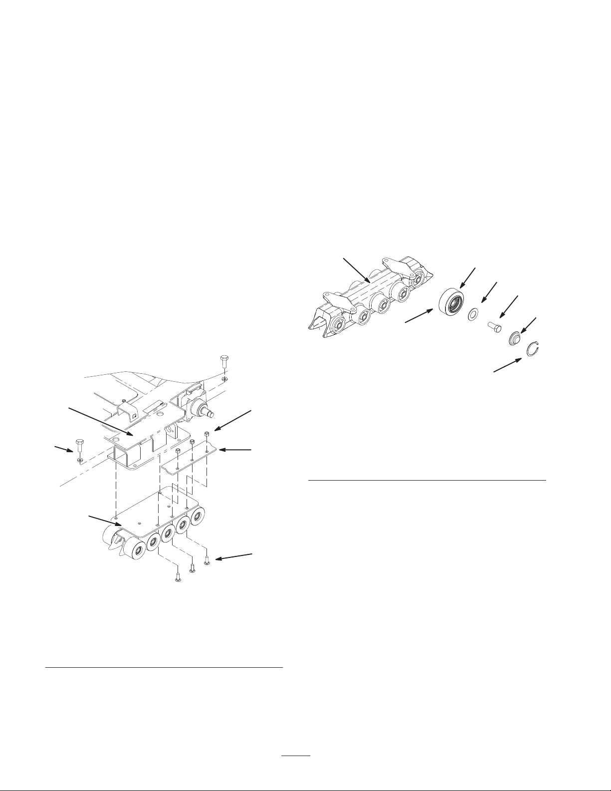
1. Assemble the new track guide and wheels as shown in
Figure 2.
2. Add grease between the bearing and the seal behind the
wheel (Fig 2).
3. Install the new road wheel onto the track guide using
the gasket in the kit and a new bolt (5/8 x 1-1/2 inch) as
shown in Fig. 2.
4. Torque the road wheel bolt to 135 to 165 ft-lb (183 to
223 N⋅m).
1. Lower the loader arms, stop the engine, and remove the
key.
2. Lift/support the side of the unit to be worked on so that
the track is three to four inches (7.6 to 10 cm) off of the
ground.
3. Remove the track from the machine. Refer to the
Operator’s Manual for more information.
4. Remove the existing track guide from the frame by
removing the three carriage bolts and lock nuts securing
the guide and clamp plate to the frame (Fig. 1). Discard
the clamp plate.
5
6
4
2
5. Fill the road wheel cap with grease and place it over the
bolt head (Fig 2).
6. Secure the road wheel cap with a snap ring (Fig 2).
1
2
3
4
7
m–7731
6
Figure 2
1. Track guide
2. Wheel
3. Gasket
4. Bolt, 5/8 x 1-1/2 inch
5. Wheel cap, add grease
under the cap
6. Snap ring
7. Add grease behind the
wheel between the
bearing and the seal
5
1
3
m–7730
Figure 1
Left-hand side shown
1. Track guide
2. Clamp plate
3. Carriage bolt
4. Locknut
5. Frame
6. Bolt and lock washer
5. Remove the two bolts and two lock washers securing
the track guide to the frame (Fig. 1). Remove the track
guide and fasteners and discard.
7. Repeat Steps 1–6 for all ten wheels.
2
Page 3

8. Install three carriage bolts (1/2 x 1-1/4 inch) to the
adapter plate before installing the plate to the track
guide (Fig. 3).
Important Ensure the notch in the track guide is
pointing toward the rear of the machine.
10. Install the track guide assembly to the machine using
two bolts (1/2 x 1-1/4 inch) and two lock washers
(1/2 inch) down through the frame to the adapter plate
of the track guide assembly (Fig. 4).
m–7733
m–7732
4
1
Left-hand adapter plate shown
1. Adapter plate, left
2. Carriage bolt,
1/2 x 1-1/4 inch
3. Track guide
4. Hex-head flush screw,
1/2 x 1-1/2 inch
Figure 3
5
6
7
3
5. Bolt, 1/2 x 1-1/4 inch
6. Lockwasher, 1/2 inch
7. Notch, toward the rear of
machine
2
3
7
4
5
1
6
Figure 4
2
1. Track guide assembly
2. Frame
3. Bolt, 1/2 x 1-1/4 inch
4. Lock washer, 1/2 inch
Left-hand side shown
5. Clamp plate
6. Carriage bolt,
1/2 x 1-1/4 inch
7. Locknut, 1/2 inch
11. Secure the track guide assembly to the frame installing
the clamp plate and three locknuts (1/2 inch) over the
carriage bolts installed previously as shown in (Fig. 4).
9. Install the adapter plate to the track guide (Fig. 3) using
two hex-head flush screws (1/2 x 1-1/2 inch) and two
bolts (1/2 x 1-1/4 inch) and lock washers (1/2 inch).
Note: Use the adapter plate that corresponds to the side of
the machine being worked on.
12. Install the new track to the machine. Refer to the
Operator’s Manual for more information.
13. Lower the traction unit to the ground.
Track Guide Refit:
Serial No. 220000401- 220000999
Use the following procedures for installing the Track Guide
Refit Kit on Dingo TX 425 Compact Utility Loaders with
serial numbers with range: 220000401-220000999. The
following procedure depicts the track guide refit on the
left-hand side; however, it can be used to refit the track
guide on either side.
Preparing the machine
1. Lower the loader arms, stop the engine, and remove the
key.
2. Lift/support the side of the unit to be worked on so that
the track is three to four inches (7.6 to 10 cm.) off of the
ground.
3
Page 4

3. Remove the track from the machine. Refer to the
Operator’s Manual for more information.
3. Torque the road wheel bolt to 135 to 165 ft-lb (183 to
223 N⋅m).
4. Remove the 4 bolts and 4 lock washers securing the
existing track guide to the frame (Fig. 5). Remove the
track guide and fasteners and discard.
1
3
1
1
1
2
m–7734
Figure 5
Left-hand side shown
1. Bolt and lockwasher
2. Track guide
3. Frame
Installing the Track Guide
1. Assemble the new track guide and wheels as shown in
Figure 6.
2. Add grease between the bearing and the seal behind the
wheel (Fig 6).
1
2
3
4
4. Install the new road wheel onto the track guide using
the gasket in the kit and the bolt (5/8 x 1-1/2 inch) as
shown in (Fig. 6).
5. Fill the road wheel cap with grease and place it over the
bolt head (Fig 6).
6. Secure the road wheel cap with a snap ring (Fig 6).
7. Repeat Steps 1–6 for all ten wheels.
8. Install the track guide assembly to the machine using
four bolts (1/2 x 1-1/4 inch) and four lock washers
(1/2 inch) down through the frame to the track guide
assembly (Fig. 7).
Important Ensure the notch in the track guide is
pointing toward the rear of the machine.
1
2
4
1
1
2
5
2
1
3
m–7735
Figure 7
Left-hand side shown
1. Bolt, 1/2 x 1-1/14 inch
2. Lockwasher, 1/2 inch
3. Track guide assembly
4. Frame
5. Notch, toward the rear of
machine
2
m–7731
1. Track guide
2. Wheel
3. Gasket
4. Bolt, 5/8 x 1-1/2 inch
5. Wheel cap, add grease
under the cap
7
Figure 6
6
6. Snap ring
7. Add grease behind the
wheel between the
bearing and the seal
5
9. Install the new track to the machine. Refer to the
Operator’s Manual for more information.
10. Lower the traction unit to the ground.
4
 Loading...