

Page 1
CE Kit
for Dingo Backhoe
Part No. 106-7705
Loose Parts
Note: Use the chart below to identify parts for assembly.
Form No. 3350-228
Installation Instructions
Description
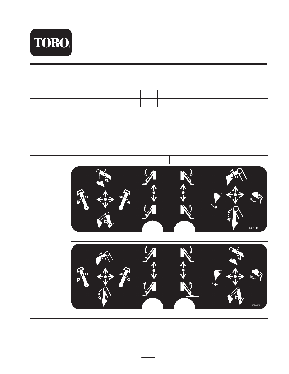
Control panel decal, 104-9956 1 Installing the CE decal
Installing the Decal
Install the CE decal over the English decal on the backhoe.
Install the decal as follows:
1. Thoroughly clean the area where you will install the
decal.
Location
US English CE
Qty. Use
2. Dampen the area with water or mildly soapy water.
3. Peel the decal from the backing and install it in place.
4. Squeegee across the surface of the decal, starting at the
center of the decal and working toward the edges using
overlapping strokes.
On console
2003 by The Toro Company
8111 Lyndale Avenue South
Bloomington, MN 55420-1196
100-4138 (US English)
104-6072 (CE)
1
Contact us at www.Toro.com
All Rights Reserved
Printed in the USA
Page 2
Switching the Hydraulic Hoses
1. Stop the engine, remove the key, install the boom pins,
and allow the engine and hydraulic system to cool
completely.
4. Remove the 6 locknuts securing the control access
panel (Fig. 1) and remove the panel.
2
2. Cycle the hydraulic lever to remove pressure from the
hydraulic lines.
Warning
Hydraulic fluid escaping under pressure can
penetrate skin and cause injury.
• Make sure all hydraulic fluid hoses and lines are
in good condition and all hydraulic connections
and fittings are tight before applying pressure to
the hydraulic system.
• Keep your body and hands away from pin hole
leaks or nozzles that eject high pressure
hydraulic fluid.
• Use cardboard or paper to find hydraulic leaks.
• Safely relieve all pressure in the hydraulic
system before performing any work on the
hydraulic system.
• Get immediate medical help if fluid is injected
into skin.
3. Disconnect the hydraulic couplers from the traction
unit.
1
m–4587
Figure 1
1. Control access panel 2. Control cover plate
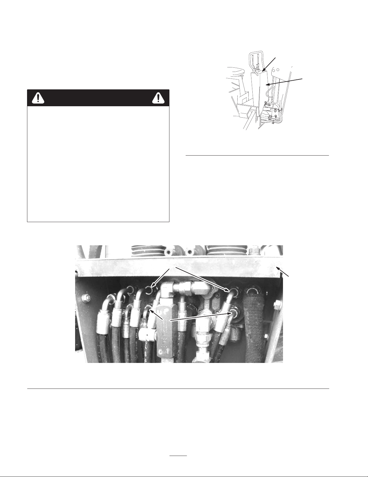
5. Remove the 4 screws securing the control cover plate
(Fig. 1 and 2) and remove the plate.
6. Disconnect the lower hydraulic hoses indicated in
Figure 2.
Note: Some hydraulic fluid may leak when you disconnect
the hoses.
7. Swap the hoses (i.e., place the right hose in the left
fitting and the left hose in the right fitting) and tighten
the fittings.
1
2
Figure 2
1. Upper hydraulic hoses 2. Lower hydraulic hoses 3. Control cover plate
8. Disconnect the upper hydraulic hoses indicated in
Figure 2.
Note: Some hydraulic fluid may leak when you disconnect
the hoses.
9. Swap the hoses (i.e., place the right hose in the left
fitting and the left hose in the right fitting) and tighten
the fittings.
10.Replace and secure the control cover plate and access
panel.
3
2
 Loading...