

Page 1
Brake Kit
Dingo TX 420 & 425 Compact Utility Loader
Part No. 106–7580 & 106–7581
Installation Instructions
Loose Parts
Note: Determine the left and right sides of the machine from the normal operating position.
Description Qty. Use
Drive wheel
Brake rim
Wheel hub
Brake plate 1 Removing the brake assembly
Brake block 1 Installing the brake block
1
2
2
1
1
1
Removing the rear wheel
Form No. 3329-412
Hex socket screw, 3/8 x 1-1/4 inch
Lock washer, 3/8 inch
1
Found in 106-7580 only
2
Found in 106-7581 only
This kit requires parts to be welded to the chassis. Welding can expose you to a number of
hazards including toxic fumes, smoke, dust, burns, fires, explosions, electric shock, radiation,
noise, and heat stress which can cause serious injury and death.
• Welding portions of the kit should be performed by a trained welder.
• Weld in a adequately ventilated area with suitable fire extinguishing equipment readily
available.
• Weld in a firesafe workplace. This can be accomplished by welding behind firesafe barriers or
curtains and on concrete or other firesafe flooring. Remove or protect all combustibles from
ignition sources.
• Wear proper protective clothing when welding, such as fire retardant coveralls. Protect your
hands with leather gauntlet gloves. Feet should be protected by high top leather shoes,
preferably safety shoes.
• Protect your eyes when welding. A welding helmet or hand shield with filter plate and cover
plate is mandatory to protect the eyes while welding. Transparent goggles or safety glasses
should be worn at all times.
2
Installing the brake assembly
2
Warning
2003 by The Toro Company
8111 Lyndale Avenue South
Bloomington, MN 55420-1196
All Rights Reserved
Printed in the USA
1
Page 2
Installation
Preparing the Unit
1. Lower the loader arms, stop the engine, and remove the
key.
2. Open the rear access cover and disconnect the negative
battery cable.
4. Push the tension wheel toward the rear of the unit to
move the fork tube against the frame (Fig. 2). (If it does
not touch the frame, continue turning the tensioning
screw until it does.)
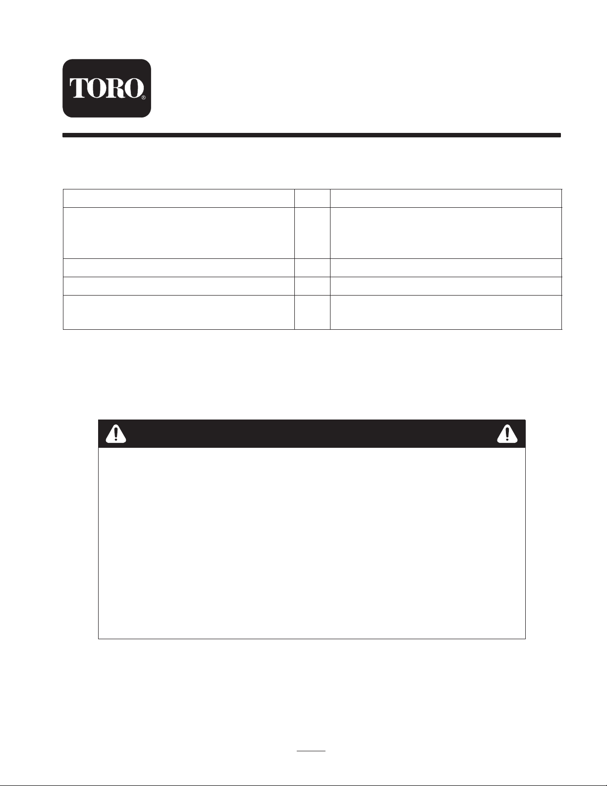
5. Begin removing the track at the top of the tension
wheel, peeling it off of the wheel while rotating the
track forwards.
6. When the track is off of the tension wheel, remove it
from the drive wheel and road wheels (Fig. 2).
Removing the Track
(Dingo TX 420)
1. Lift/support the side of the unit to be worked on so that
the track is three to four inches (7.6 to 10 cm.) off of the
ground.
2. Remove the tensioning screw locking bolt and nut
(Fig. 1).
4
1. Locking bolt
2. Tensioning screw
3. Using a 1/2 inch drive socket, release the drive tension
by turning the tensioning screw clockwise (Fig. 2).
1
5
m–4774
1. Track
2. 1/2 in. socket
3. Tension wheel
4. Fork tube
23
1
Figure 1
3
4
8
Figure 2
Dingo TX 420
m–4747
3. Tension tube
4. Tension wheel
7
6
2
5. Track lug
6. Drive wheel
7. Wheel spacer
8. Road wheels
7. Repeat steps 1–6 for the opposite track when installing
a second brake kit.
Removing the Track
(Dingo TX 425)
1. Lift/support the side of the unit to be worked on so that
the track is three to four inches (7.6 to 10 cm.) off of the
ground.
2. Remove the tensioning screw locking bolt and nut (Fig.
1).
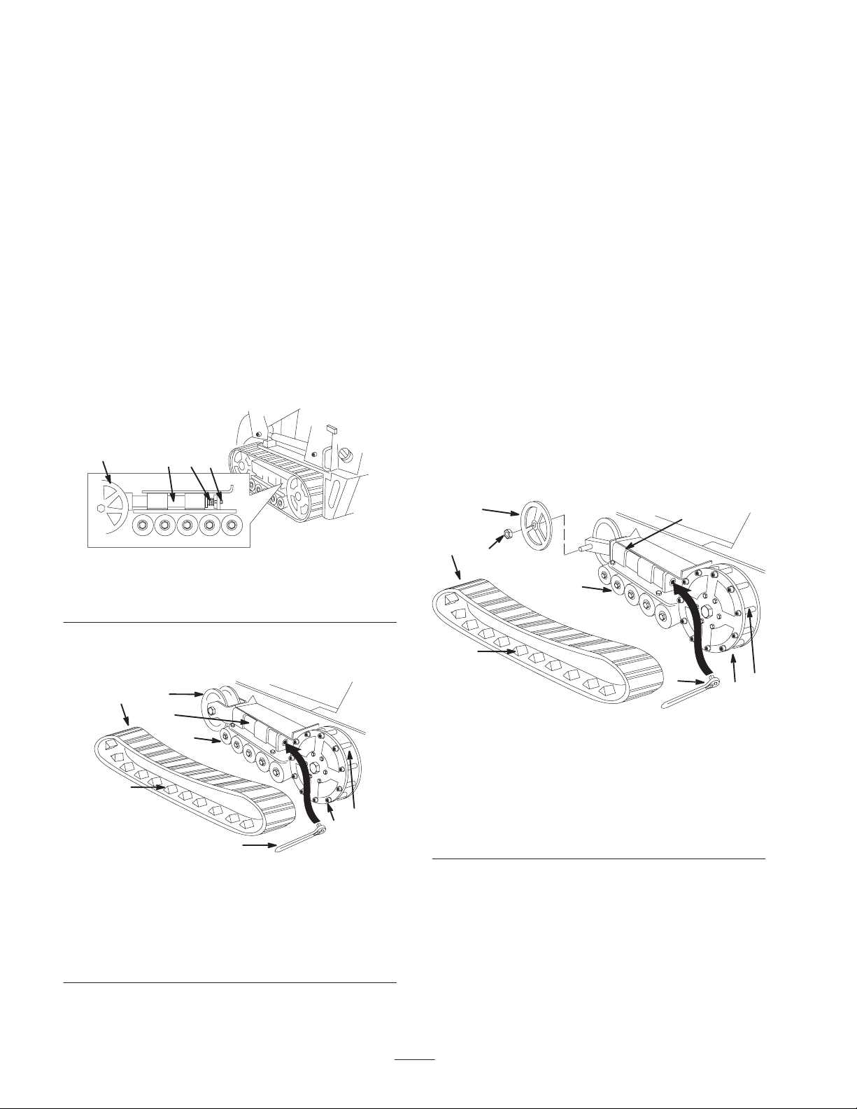
3. Using a 1/2 inch drive socket, release the drive tension
by turning the tensioning screw clockwise (Fig. 3).
4
1
3
9
6
Figure 3
Dingo TX 425
1. Track
2. 1/2 in. socket
3. Tension wheel nut
4. Outer tension wheel
5. Fork tube
6. Track lug
7. Drive wheel
8. Wheel spacer
9. Road wheels
4. Push the tension wheel toward the rear of the unit to
move the fork tube against the frame (Fig. 3). (If it does
not touch the frame, continue turning the tensioning
screw until it does.)
5. Remove nut securing outer tension wheel and remove
wheel.
5
2
m-6706
8
7
2
Page 3
6. Begin removing the track at the top of the tension
wheel, peeling it off of the wheel while rotating the
track forwards.
Removing the Rear Drive
Wheel (Dingo TX 425)
7. When the track is off of the tension wheel, remove it
from the drive wheel and road wheels (Fig. 3).
8. Repeat steps 1–6 for the opposite track when installing
a second brake kit.
Removing the Rear Wheel
(Dingo TX 420)
1. Remove the cotter pin and wheel nut. Remove the rear
wheel assembly from the motor shaft. (Fig. 4)
5
6
8
9
4
7
8
1
2
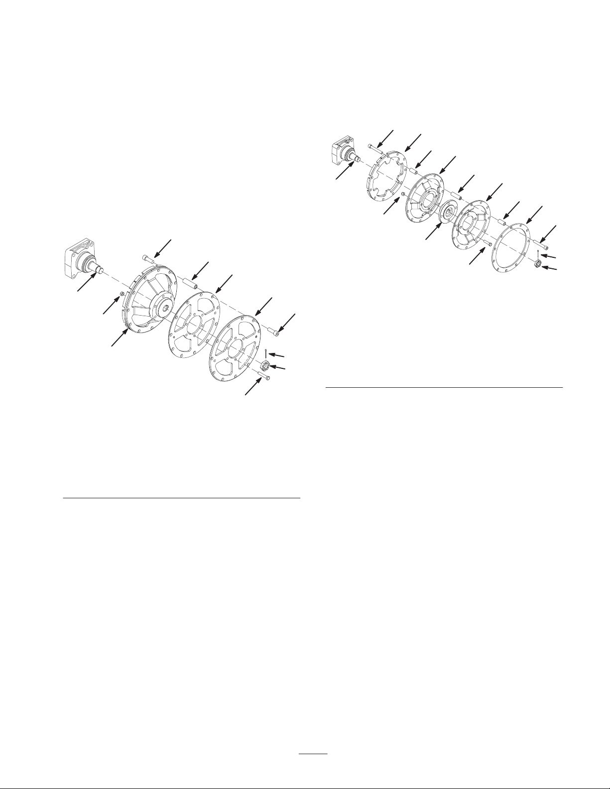
1. Remove the cotter pin and motor wheel nut. Remove
the rear wheel assembly from the motor shaft. (Fig. 5)
5
8
6
9
7
12
4
9
6
11
5
10
1
m–6668
3
2
Figure 5
5
1. Cotter pin
2. Wheel nut
3. Bolt, 1/2 x 1-3/4 inch
4. Nut, 1/2 inch
5. Hex socket screw, 1/2 x
1-1/2 inch
6. Spacer, short
7. Spacer, long
8. Brake rim
9. Drive wheel
10. Wheel hub
11. Wheel plate
12. Motor shaft
m–6667
3
Figure 4
1. Cotter pin
2. Wheel nut
3. Bolt, 3/8 x 2 inch
4. Nut, 3/8 inch
5. Hex socket screw, 1/2 x
1-1/2 inch
6. Spacer
7. Drive wheel
8. Wheel plate
9. Motor shaft
2. Disassemble the rear wheel by removing the 22 hex
socket screws and spacers securing the outer ring of the
wheel assembly, and then remove the six bolts and nuts
on the inner ring of the wheel assembly (Fig. 4).
3. Save the fasteners, spacers, and the wheel plates.
4. Discard the drive wheel.
5. Assemble the wheel installing the new drive wheel.
6. Torque the hex socket screws and the inner bolts to 27
to 33 ft-lb (37 to 45 N⋅m).
7. Set the wheel assembly, cotter pin, and wheel nut aside.
8. Repeat steps 1-7 for opposite side when installing a
second brake kit.
2. Disassemble the rear wheel by removing the 22 hex
socket screws, long spacers, and short spacers securing
the outer ring of the wheel assembly, and then remove
the four bolts and nuts on the inner ring of the wheel
assembly (Fig. 5).
3. Save the fasteners, spacers, drive wheels, and wheel
plate.
4. Discard the brake rim assembly and wheel hub.
5. Assemble the wheel, installing the new brake rim
assembly and wheel hub.
6. Torque the hex socket screws and the inner bolts to 67
to 83 ft-lb (91 to 113 N⋅m).
7. Set the wheel assembly, cotter pin, and wheel nut aside.
8. Repeat steps 1-7 for opposite side when installing a
second brake kit.
3
Page 4

Removing Gas Tank and
Battery
Remove the gas tank to access the brake assemblies and
prepare the machine for welding.
Removing the Gas Tank
6. Slide the fuel tank to the rear (Fig. 6).
7. Disconnect the fuel line.
8. Disconnect the two wires leading to the right side of the
tank.
9. Carefully remove the tank and set it upright to keep
from spilling the gasoline.
Danger
In certain conditions, gasoline is extremely
flammable and highly explosive. A fire or
explosion from gasoline can burn you and others
and can damage property.
• Remove the fuel tank outdoors in an open area.
Wipe up any gasoline that spills.
• Do not remove the fuel tank near an open flame
or where gasoline fumes may be ignited by a
spark.
• Do not smoke while handling the fuel tank.
1. Remove the bolts, washers, and lock washers securing
the two side weights, removing the weights (Fig. 6).
1
3
5
4
10.Move the tank a safe distance away from the work area.
11. Wipe up any flammable fluids.
Removing the Battery
Warning
Battery posts, terminals, and related accessories
contain lead and lead compounds, chemicals
known to the State of California to cause cancer
and reproductive harm. Wash hands after
handling.
1. Remove the bolts, nuts, and clamp securing the battery
(Fig. 7).
5
1
6
2
3
4
m–5917
2
1
m–4773
Figure 6
1. Side weights
2. Rear panel
3. Fuel tank bracket
4. Fuel tank
5. Chassis
2. Remove the three carriage bolts and washers from the
battery base and the fuel tank bracket, removing the
bracket (Fig. 6).
3. Remove the six nuts and bolts securing the rear panel,
removing the panel (Fig. 6).
4. Loosen the tank cap to relieve pressure.
5. Place a clamp on the fuel line, two inches from where it
comes out of the fuel tank.
Figure 7
1. Battery
2. Clamp
3. Positive cable
4. Rubber cover
5. Negative cable
6. Bolts and nuts
2. Tilt the top of the battery rearward and slide it out of the
traction unit.
Important Do not allow the battery posts to touch the
frame or hydraulic lines or it may cause sparks.
4
Page 5

Removing the Brake Assembly
1. Remove the bolts and lock washers securing the brake
assembly to the chassis and set aside for later use
(Fig. 8).
3
5. Repeat steps 1-4 the opposite brake assembly when
installing second brake kit.
Installing New Brake Plates
Perform the following procedure for both assemblies when
installing a second brake kit.
1. Remove the hex socket head bolt, jam nut, and locknut
as shown in Figure 9.
2
1
m–6664
Figure 8
Brake assembly and chassis shown from the left side.
1. Bolts
2. Lock washers
3. Brake assembly
2. Remove the cotter and clevis pin from the brake cable
(Fig 9).
6
9
10
7
2
11
13
2. Remove the two bolts and locknuts securing the brake
stop to the plate.
3. Slide the plate out and discard it.
4. Slide the new plate into the assembly.
5. Replace the brake stop and fasteners.
6. Replace the hex socket head screw, jam nut, and
locknut. Be sure to attach the extension spring as you
assemble the fasteners and install them to the brake
plate.
7. Set the assembly aside for later use.
Removing the Brake Channel
Note: Avoid damaging the chassis or wheel motor when
removing the brake channel.
1. With an appropriate tool, cut off old brake block
(Fig. 10).
1
2
1
4
3
12
3
5
8
m–6663
4
Figure 9
1. Brake plate housing
2. Brake cable
3. Clevis pin
4. Cotter pin
5. Cable hook
6. Bolt, 1/4 x 5/8 inch
7. Brake stop
8. Locknut, 1/4 inch
9. Extension spring
10. Hex socket screw, 5/16 x
2 inch
11. Jam nut, 5/16 inch
12. Locknut, 5/16 inch
13. Brake plate
3. Remove the cable from the bracket hook as shown in
Figure 9.
4. Remove the brake assembly.
1
5
m–6662
Figure 10
1. Brake channel
2. Brake block
3. Weldment
4. Socket holes
5. New brake block
2. Grind or file down the remaining channel to create a
clean and level surface.
3. Wipe down surface to remove loose debris.
4. Repeat steps 1-3 for the opposite side if installing a
second brake kit.
5
Page 6

Installing the Brake Block
1. Attach the brake cable to the assembly by installing the
cotter and clevis pins and by hooking the line into the
bracket at the clip ring as shown in Figure 9.
2. Install a brake assembly into position using the
fasteners removed previously (Fig. 9).
3. Engage the parking brake to extend the brake plate.
4. Place the new brake block over the brake plate to line
up the block between, and level with, the two
surrounding socket holes (Fig. 10).
5. Spot weld the block into position on the surface of the
chassis.
3. Torque the hex socket screws to 67 to 83 ft-lb (91 to
113 N⋅m).
2
6. Disengage the parking brake.
7. Remove the bolts and lock washers securing the brake
assembly. Discard the fasteners.
Note: The brake assembly stay in position while the new
brake block is being welded.
8. Weld the new brake block to the frame with a quarter
inch fillet on the left, top and right sides of the block as
shown in Figure 10.
Important Do not weld the brake block out of position
or allow the weldment to cover the surrounding bolt holes.
9. Allow the weldments to cool.
10.Prime and paint the area with a touch-up paint.
11. Repeat steps 1-10 for the opposite side if installing
when second brake kit.
Installing the Brake Assembly
Note: Install the left side brake assembly before installing
the right side brake assembly.
1. Move the brake assembly into position making sure the
brake plate is in place within the new brake block.
1
m–6664
Figure 11
Brake assembly and chassis shown from the left side.
1. Hex socket screws, 3/8 x
1-1/4 inch
4. Manually test the brakes to verify that the brake plate
moves through the brake block freely.
5. Repeat steps 1-4 for the opposite brake assembly when
installing a second brake kit.
2. Lock washers, 3/8 inch
Installing the Gas Tank
1. Slide the fuel tank part way into the chassis (Fig. 6).
2. Connect the fuel line and remove the clamp.
3. On the right side of the tank, connect the orange wire to
the center post and the black wire to the outside post
(Fig. 12).
2. Secure the brake assembly using the hex socket head
screws and lock washers included with the kit (Fig. 11).
2
1
m–4776
Figure 12
1. Black wire 2. Orange wire
6
Page 7

4. Slide the tank all the way into the traction unit.
Important The fuel line and wires must be away from
the engine pulleys and the frame.
5. Replace the rear panel and secure it with the six bolts
and nuts removed previously (Fig. 6).
4. Turn the tensioning screw counter-clockwise until the
distance between the tension nut and the back of the
fork tube (Fig. 13) is 2-3/4 inch (7 cm).
m–4775
6. Place the fuel tank bracket over the tank and secure it
and the battery tray with the bolts and washers removed
previously (Fig. 6).
7. Install the side weights with the bolts, washers, and lock
washers removed previously (Fig. 6).
8. Close the rear access cover.
Installing the Rear Drive Wheel
1. Clean the inside wheel hub and motor shaft with a
degreaser prior to installing the rear drive wheel.
2. Install the rear drive wheel over the motor shaft (Fig. 4
or 5). Be sure to line up the keyway in the hub with the
key in the motor shaft.
3. Install the wheel nut on the motor shaft so that the
cotter pin hole is accessible (Fig. 4 or 5).
4. Torque the nut to 250 to 300 ft-lb (271 to 407 N⋅m).
Note: Do not loosen the nut to allow for the cotter pin to be
installed. If the hole is covered by the nut, tighten the nut to
allow the cotter pin to be installed.
5. Install the cotter pin into the hole in the motor shaft and
bend the ends.
6. Repeat steps 1-5 for opposite side when installing a
second brake kit.
1
Figure 13
1. 2-3/4 inch (7 cm)
5. Align the closest notch in the tension screw to the
locking bolt hole and secure the screw with the locking
bolt and nut.
6. Lower the traction unit to the ground.
7. Repeat steps 1–6 for the opposite track when installing
a second brake kit.
Installing the Track
(Dingo TX 425)
1. Beginning at the drive wheel, coil the new track around
the wheel, ensuring that the lugs on the track fit
between the spacers on the wheel (Fig. 3).
2. Push the track under and between the road wheels
(Fig. 3).
Installing the Track
(Dingo TX 420)
1. Beginning at the drive wheel, coil the new track around
the wheel, ensuring that the lugs on the track fit
between the spacers on the wheel (Fig. 2).
2. Push the track under and between the road wheels
(Fig. 2).
3. Starting at the bottom of the tension wheel, install the
track around the wheel.
3. Starting at the bottom of the tension wheel, install the
track around the inner wheel.
4. Install the outer tension wheel and secure it with the
tension wheel nut.
5. Torque the nut to 250 to 300 ft-lb (271 to 407 N⋅m).
6. Turn the tensioning screw counter-clockwise until the
distance between the tension nut and the back of the
fork tube (Fig. 13) is 2-3/4 inch (7 cm).
7. Align the notch in the tension screw to the locking bolt
hole and secure the screw with the bolt and locking nut.
8. Lower the traction unit to the ground.
9. Repeat steps 1–8 for the opposite track when installing
a second brake kit.
7
Page 8

 Loading...