

Page 1
Form No. 3328–954
Bagger Adapter Kit
2002 Z100 DFS Bagger to Fit to 2003 and Later Z100
Z Masters
Part No. 106–7131
Installation Instructions
This kit is for installing 2002 Z100 DFS Baggers onto 2003 and Later Z100 Z Masters with a serial number of 230005001
and up.
Note: Models 74176 and 74176TE do not use this kit.
Loose Parts
Note: Use the chart below to verify all parts have been shipped.
Step Description Qty. Use
1
2
3
No parts needed. Drilling hole in the engine strap
Temporarily use parts from Step 3. Drilling holes in the bumper
Bolt, 5/16 x 1 inch
Flange nut, 5/16 inch
Flat washer, 5/16 inch
Before Installation
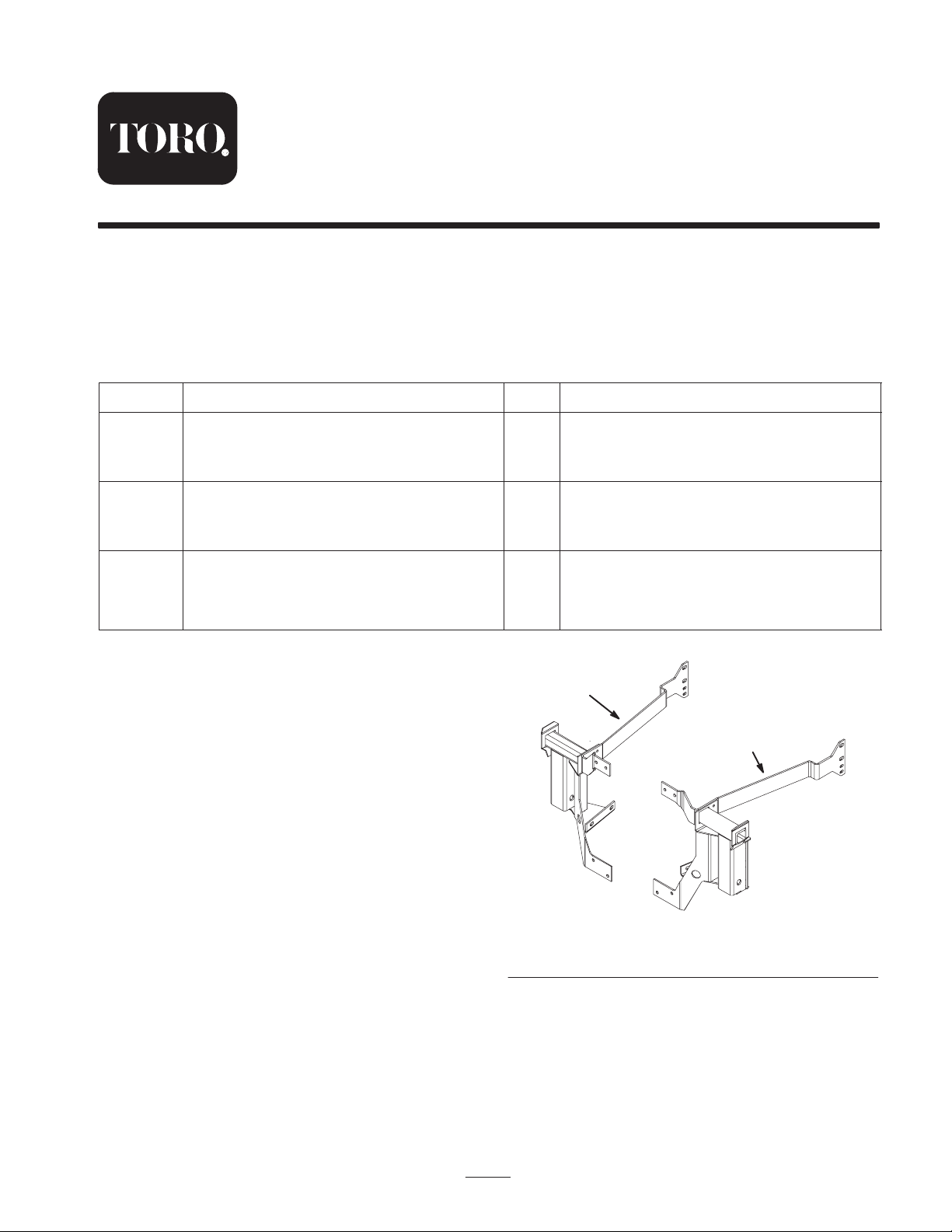
Discard the Left and Right Mounting
Brackets
Do not use the left and right mounting brackets shown in
Figure 1.
16
16
16
Installing the bagger mounting assembly
1
2
2002 by The Toro Company
8111 Lyndale Avenue South
Bloomington, MN 55420-1196
Figure 1
1. Left mounting bracket 2. Right mounting bracket
All Rights Reserved
1
Printed in the USA
m–6333
Page 2
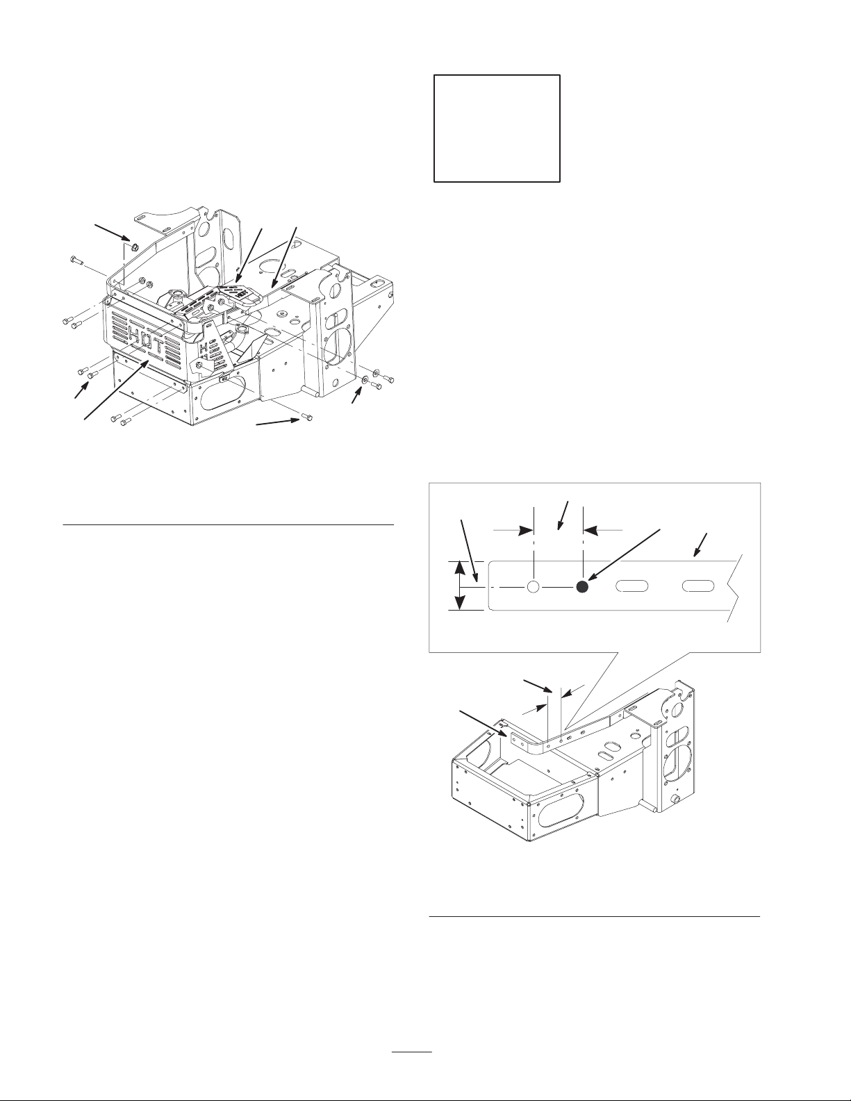
Removing the Heat Shields
1. Remove the rear heat shield from the back of the
machine (Fig. 2).
Step
2. Remove the muffler heat shield from the right engine
strap and above the muffler tailpipe (Fig. 2). Save one
bolt, flat washer and nut.
3
5
4
1
Figure 2
1. Rear heat shield
2. Muffler heat shield
3. Right engine strap
2
4
4. Bolts
5. Nuts
6. Flat washer
6
m–6328
1
No Parts needed for this step.
Drilling a Hole in the Engine
Strap
Check for an exiting hole in the engine strap (Fig. 3).
Perform the following procedures if one does not exist.
1. Place a mark, on the right engine strap, 2 inches
(51 mm) in front of the hole shown in Figure 3. Center
the mark between the top and bottom edges of the
engine strap.
2. At the mark, center punch and drill a 11/32 inch hole
into the engine strap (Fig. 3).
3
4
2
1
1
1. Right engine strap
2. Hole to drill
2
3
m–6329
Figure 3
3. 2 inches (51 mm)
4. Center line
Page 3
Step
4
3
2
Temporarily use parts from Step 3.
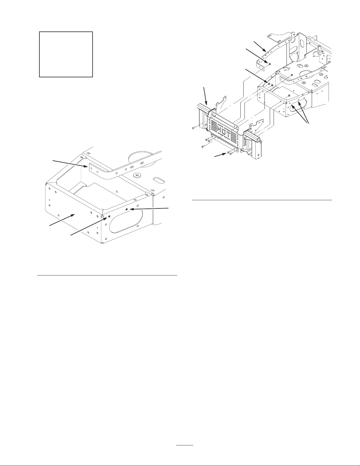
Drilling Holes in the Bumper
Check for exiting holes in the side of the bumper (Fig. 4).
Perform the following procedures if holes do not exist.
3
1
2
m–6348
3
1
5
2
Figure 5
1. Bagger mounting
assembly
2. Bolt, 5/16 x 1 inch
2
3. Flange nut, 5/16 inch
4. Engine strap
5. Hole to drill
m–6347
Figure 4
1. Bumper
2. Hole to drill, 11/32 inch
3. Using the bagger mounting assembly as a template,
install the bagger mounting assembly to the engine
straps with 2 bolts (5/16 x 1 in.) and 2 flange nuts
(5/16 in.) (Fig. 5).
4. Install the bagger mounting assembly to the back of
the bumper with 4 bolts (5/16 x 1 in.) and 4 flange nuts
(5/16 in.) (Fig. 5).
5. Mark and center punch the 2 hole locations on both
sides of the bumper (Fig. 4).
6. Remove the bagger mounting assembly (Fig. 5).
7. Drill 4 pilot holes, 1/8 in. diameter, at the marked
locations. (Fig. 5).
8. Drill 4 holes, 13/32 in. diameter, through the 1/8 in.
pilot holes. (Fig. 5).
3. Engine strap
3
Page 4

Step
m–6331
3
Parts needed for this step:
• 16 Bolts, 5/16 x 5/8 inch
• 16 Flange nuts, 5/16 inch
• 16 Flat washers, 5/16 inch
Installing the Bagger Mounting
Assembly
1. Place the bagger mounting assembly up between the
two engine straps (Fig. 6).
2
1
1
4
2
3
1
1. Bagger mounting
assembly
2. Bolt, 5/16 x 1 inch
3
2
Figure 7
5
5
3. Flat washer, 5/16 inch
4. Flange nut, 5/16 inch
5. Bumper
2
Figure 6
1. Bagger mounting
assembly
2. Install the bottom part of the bagger mounting
assembly to the bumper with 8 bolts (5/16 x 1 inch),
8 flat washers (5/16 inch) and 8 flange nuts (5/16 inch)
(Fig. 7).
2. Engine strap
m–6330
4
Page 5

3. Install the muffler heat shield to the right engine strap
with one existing bolt, flat washer and flange nut
(Fig. 8).
2
1
m–6332
3
Figure 8
1. Existing bolt
2. Existing nut
3. Existing flat washer
4. Install the top part of the bagger mounting assembly to
the engine straps and muffler heat shield with 8 bolts
(5/16 x 1 inch), 8 flat washers (5/16 inch) and 8 flange
nuts (5/16 inch) (Fig. 9).
1
2
3
1
m–6337
3
Figure 9
1. Bolt, 5/16 x 1 inch
2. Nut, 5/16 inch
3. Flat washer, 5/16 inch
1
5. Install the remaining parts of the bagger using the
instructions included with it.
5
Page 6

678
Page 7

Page 8

 Loading...