

Page 1

Striping Kit
44 inch and 52 inch Mid Size and Z Master Mowers
Part No. 106–3370
Loose Parts
Note: Use the chart below to identify parts used for assembly.
Description Qty. Use
Form No. 3329-363
Installation Instructions
Mounting bracket
Wiper
Hex lock nut, 1/4 inch
Hex head screw, 1/4 x 3/4 inch (19mm)
Flat washer, 1/4 inch
Speed nut, 1/4 inch
Parts catalog 1
Installation instructions 1 Read before installing
Modifying the Wiper
Use this procedure and appropriate figure for
modifying the wiper for installation on each specific
mower.
1. Using the dimensions shown in the appropriate figure,
locate, mark, and cut off excess material on wiper. Note
the position and location of holes.
Note: Make sure to cut a 1/2 inch wide notch at locations
specified.
8
1
8
16
8
8
Installation of kit
Z Master Wipers
Z Master 100 Series 44 inch Mower
Cut notch here
41–3/4”
1–3/4”
7/8”
2003 by The Toro Company
8111 Lyndale Avenue South
Bloomington, MN 55420-1196
Cut notch at second set of holes
Figure 1
Z Master 100 and 200 Series 52 inch
Mower
43–3/4”
1–5/8”
Figure 2
All Rights Reserved
Printed in the USA
1
Page 2
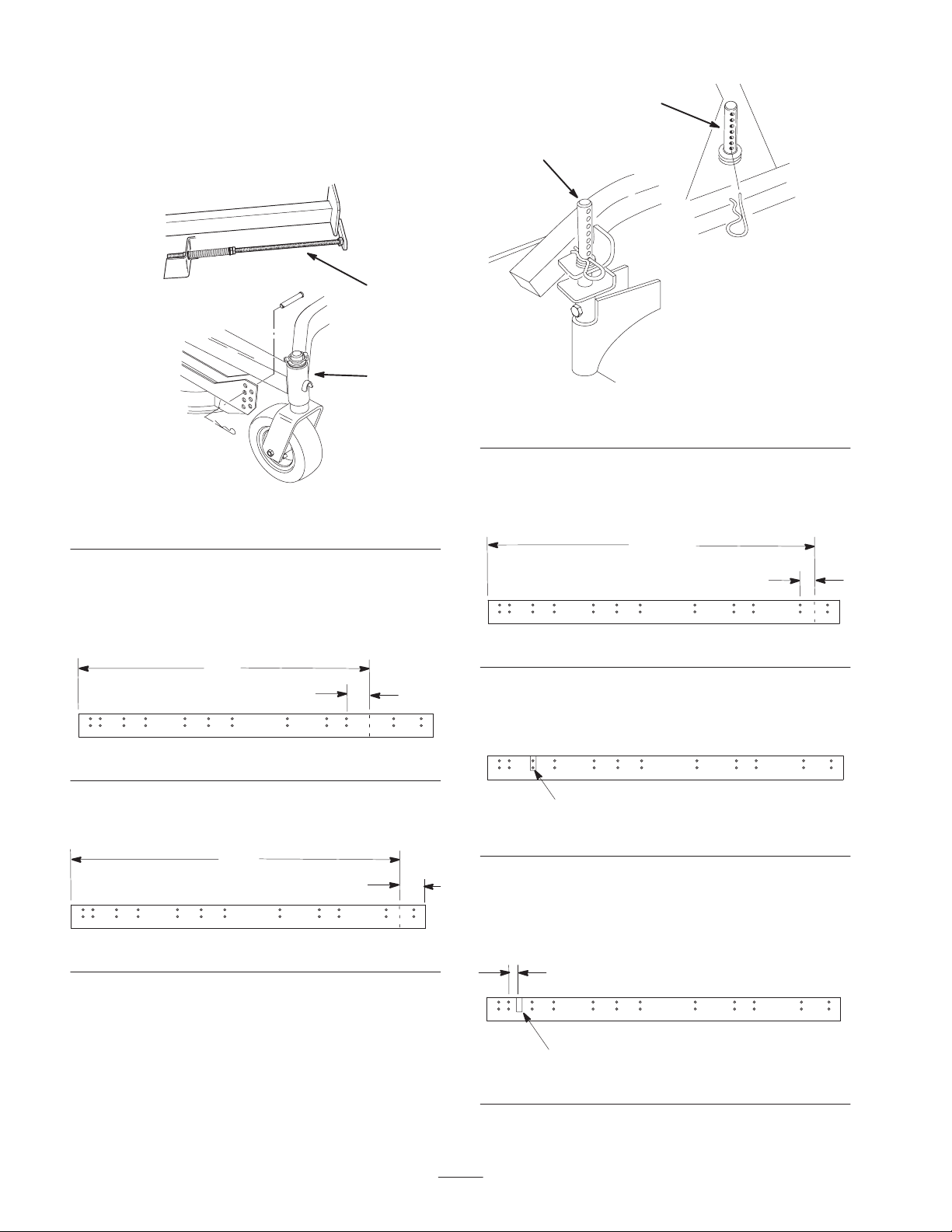
Mid Size Mower Wipers
If your Mid Size mower has a carrier frame and adjusting
rod shown in Figure 3, use Figures 4 and 5 for modifying
the wiper.
2
1
1
1
m–6563
Figure 3
1. Carrier frame 2. Adjusting rod
44 inch Mid Size Mower (Mowers with serial
numbers in the range of 210000000 thru
219999999)
37”
3”
Figure 4
52 inch Mid Size Mower
m–6365
Figure 6
1. Height–of–cut peg
44 inch Mid Size Mower
(Serial No. 230000001 and up)
41–3/4”
1–3/4”
Figure 7
52 inch Mid Size Mower
(Serial No. 230000001 and up)
Cut notch here (third set of holes)
Figure 8
43”
2”
Figure 5
If your Mid Size mower has height–of–cut pegs as shown
in Figure 6, use Figures 7, 8, and 9 for modifying the wiper.
52” Mid Size Mower (Mowers with serial
numbers in the range of 210000000 thru
219999999)
3/4”
Cut notch here
Figure 9
2
Page 3

Installing the Wiper to Mower
1. Install the speed nuts on each of the mounting brackets
as shown in Fig. 10.
3. Using flat washers and 1/4 x 3/4 inch (19 mm) screws,
loosely attach the mounting brackets (with speed nuts
assembled) to the appropriate holes in wiper (Fig. 11)
3
1
2
m–4049
Figure 10
1. 1/4–20 Speed nut 2. Mounting bracket
2. Use the following list to determine which mounting
holes are to be used for installing mounting brackets to
wiper.
Note: Hole numbers are determined from left end of wiper.
Mower Type Wiper Holes Used
Z Master 200 –52 inch
1, 3, 5, 7, 9,10 and 11
Mower
Z Master 100 –44 inch
1, 4, 6, 8, 9 and 11
Mower
Z Master 100 –52 inch
1, 3, 4, 6, 7, 9, 10 and 11
Mower
44 inch Mid Size
1, 3, 5, 7, 8 and 10
Mower (Serial
numbers 210000000
thru 219999999)
44 inch Mid Size
1, 3, 5, 7, 8, 10 and 11
Mower (Serial Number
230000001 and Up)
1
2
Figure 11
1. 1/4–20 x 3/4” (19 mm)
screw
2. Flat washer
3. Mounting bracket
w/speed nut
4. Align the brackets vertical to the wiper and tighten the
screws.
Note: Use the upper holes for greater striping effect and the
lower holes for less effect.
2
1
Figure 12
1. 1/4–20 x 3/4” (19 mm)
screw
2. 1/4–20 lock nut
52 inch Mid Size
Mower (Serial
numbers 210000000
thru 219999999)
52 inch Mid Size
Mower (Serial Number
230000001 and Up)
1, 3, 4, 5, 7, 8, 10 and 11
1, 4, 5, 7, 8, 10, 11 and 12
5. Center the wiper, with the mounting brackets
assembled, against the rear of the deck. Position the
lower leg of each mounting bracket under and up tight
against the bottom lip of the rear deck wall.
6. Using each mounting bracket as a template, locate,
mark and drill 9/32 inch diameter holes in the mower
deck.
7. Secure mounting brackets to mower deck with 1/4 x
3/4 inch (19 mm) screws and 1/4 inch lock nuts. Screw
heads to be positioned so the heads are on the inside of
the deck and nuts to the outside as shown in Fig. 12.
3
Page 4

 Loading...