

Toro 105-9361 Installation Instructions
Form No. 3327–770
Exhaust Kit
100 Series Z Master
Part No. 105–9361
Installation Instructions
Loose Parts
Note: Use the chart below to identify parts for assembly.
DESCRIPTION QTY. USE
Loom clip 1 Routing the engine cables for Kohler engines
Heat shield
Vent tube
Bracket
Screw
Left–hand guard strap 1 Installing the left–hand guard strap
Air deflector shield
Bolt, 5/16 x 3/4 in.
Nut, 5/16 in.
Clamp, 1–1/4 in.
Clamp, 1–1/8 in.
Tailpipe
Exhaust guard—left hand
Bolt, 5/16 x 3/4 in.
Nut, 5/16 in.
Exhaust guard—right hand
Bolt, 5/16 x 3/4 in.
Nut, 5/16 in.
1
1
1
1
1
4
4
1
1
1
1
3
3
1
4
4
Installing the fuel pump heat shield and vent
tube for Kawasaki engines
Installing the air deflector shield
Installing the tailpipe extension
Installing the left hand exhaust guard
Installing the right hand exhaust guard
Decal 1 Installing the decal
2002 by The Toro Company
8111 Lyndale Avenue South
Bloomington, MN 55420-1196
1
All Rights Reserved
Printed in the USA
103–2644
Before Installation
1. Stop the PTO, set the parking brake, stop the engine,
and remove the ignition key.
2
3
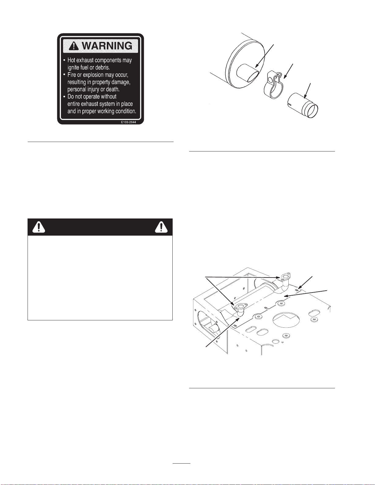
Figure 1
1. Spark arrester
2. Muffler exhaust outlet
3. Clamp
Checking the Upper Heat
Shield
1
2. Allow the traction unit and muffler to cool completely.
3. Raise the seat and disconnect the negative battery
cable.
Warning
Battery terminals or metal tools could short
against metal machine components causing
sparks. Sparks can cause the battery gasses to
explode, resulting in personal injury.
• When removing or installing the battery cables,
do not allow the battery terminals to touch any
metal parts of the machine.
• Do not allow metal tools to short between the
battery terminals and metal parts of the
machine.
Removing the Spark Arrester
1. Allow the muffler to cool completely.
2. Loosen the clamp (Fig. 1).
3. Remove the spark arrester off the exhaust outlet
(Fig. 1).
1. Locate the upper heat shield below the exhaust
manifold (Fig. 2).
2. Check to make sure the shield is adjusted as far back
as possible (Fig. 2).
3. If there is a large gap, loosen the shield fasteners
(Fig. 2).
4. Slide the upper shield back as far as possible (Fig. 2).
5. Tighten the shield fasteners (Fig. 2).
2
4
1. Upper heat shield
2. Header tubes
Figure 2
3. Fasteners
4. No gaps
3
m–5834
1
2
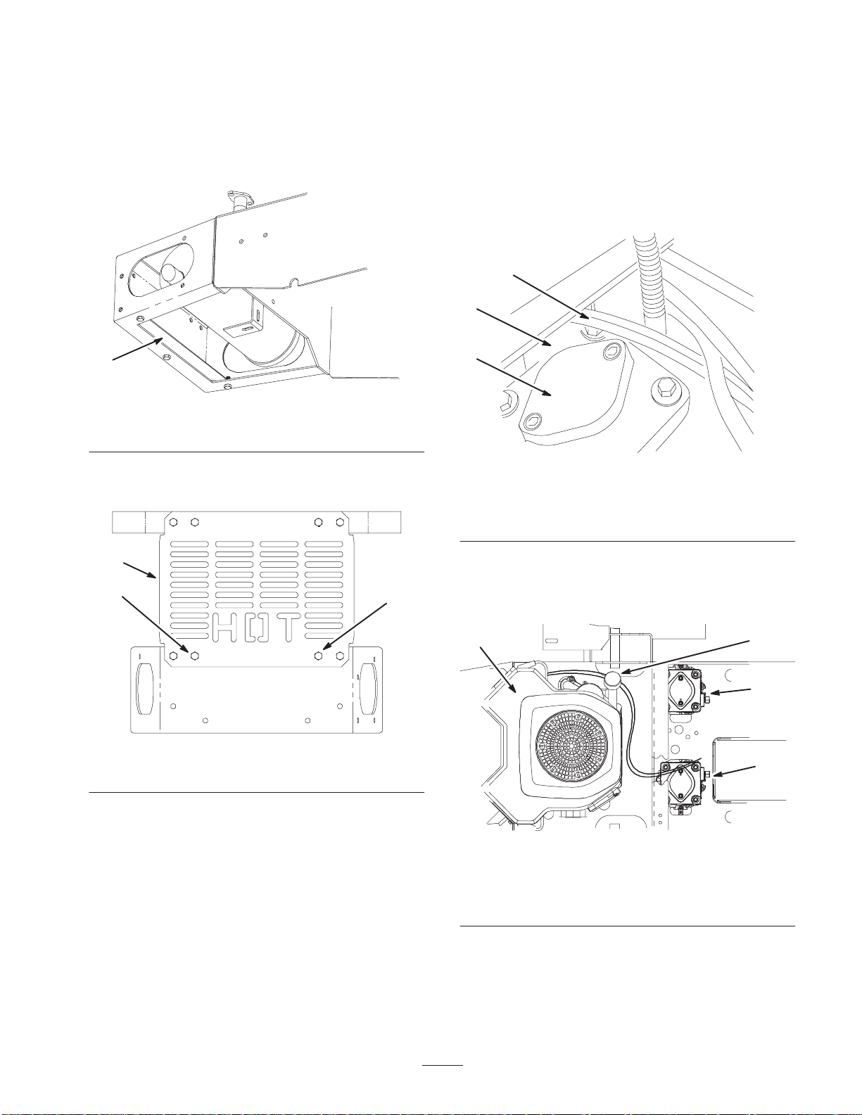
Removing the Lower Air
Deflector and Heat Shield Bolts
1. If present remove and discard the lower air deflector
(Fig. 3). The lower air deflector is located under the
rear bumper.
Note: Determine the left and right sides of the machine
from the normal operating position.
1. Disconnect throttle and choke cables from the engine
control panel (back of engine) and pull the cables to
the front of the unit (Fig. 8).
2. Route both cables over the top of the right–hand
hydraulic pump and through the large opening behind
the right–hand pump (Fig. 5).
2
3
1
m–5835
Figure 3
1. Lower air deflector
2. Remove the inner two bolts on the bottom of the rear
heat shield (Fig. 4).
1
2
2
m–5836
Figure 4
1. Rear heat shield 2. Bolt—remove
1
m–5851
Figure 5
1. Right–hand hydraulic
pump
2. Cables
3. Large opening behind
pump
3. From the right–hand hydraulic pump, route both cables
down to the engine mounting deck and around the left
side of the engine (Fig. 6).
34
2
1
Routing the Engine Cables for
Kohler Engines
Note: The following instructions are for Kohler Engines
only. This must be done to prevent damage to cable from
heat associated with the tailpipe extension.
1. Right–hand hydraulic
pump
2. Left–hand hydraulic pump
3
m–5837
Figure 6
3. Oil dipstick
4. Left side of engine
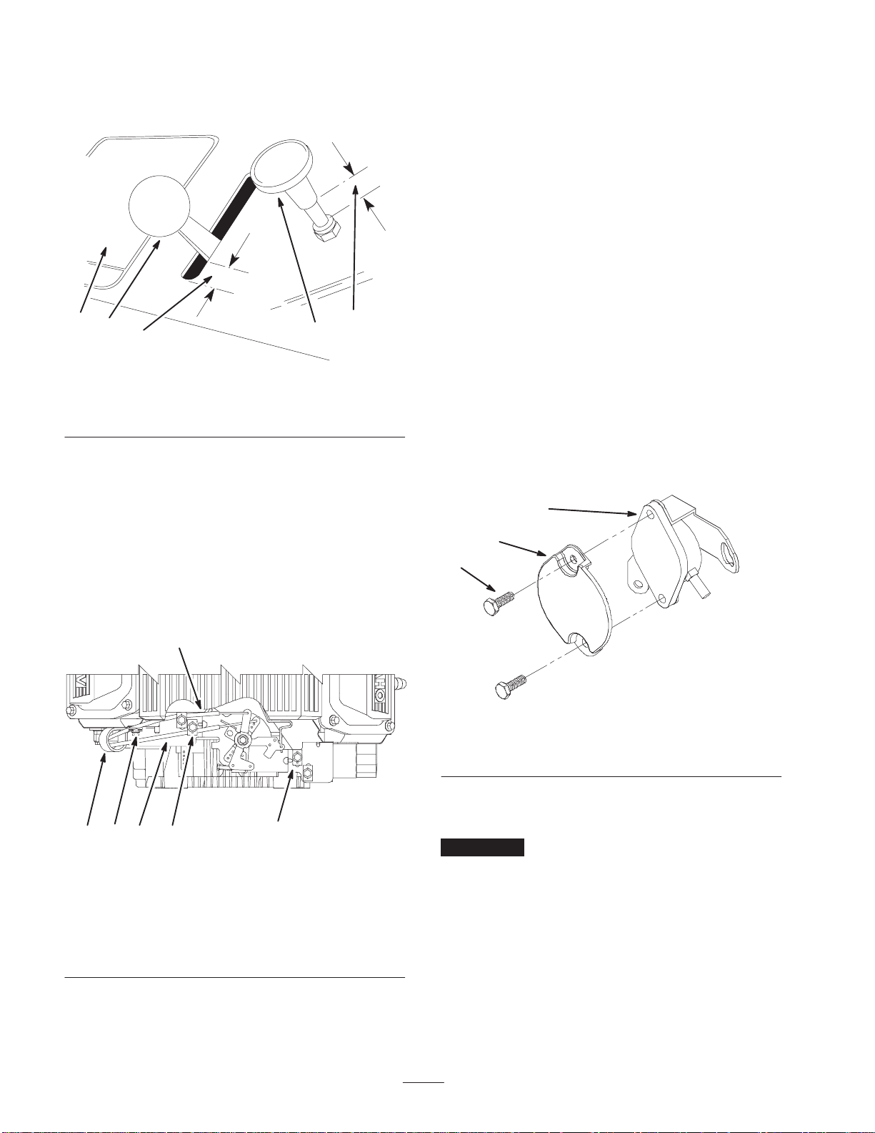
4. On the control console, position the throttle control
3/8 in. from full–throttle and extend the choke control
3/8 in. from the fully depressed or off position (Fig. 7).
1
2
4
4
3
Figure 7
1. Control Console
2. Throttle control
3. Choke control
4. 3/8 in.
m–5852
8. Adjust the throttle setting by pulling the throttle cable
until the throttle control plate rotates against the stop
on the engine control panel and tighten the throttle
cable clamp (Fig. 8).
9. Gently push the choke cable until the choke is fully
closed and tighten the choke cable clamp (Fig. 8).
Check to be sure the operator controls on the console
have not moved from the original settings in step 4.
Installing the Fuel Pump Heat
Shield and Vent Tube for
Kawasaki Engines
Note: The following instructions are for Kawasaki
Engines only.
Installing the Fuel Pump Heat Shield
1. Remove the 2 bolts that attach fuel pump to bracket
(Fig. 9).
5. Install the loom clip on the left–hand engine control
panel bolt as shown in figure 8. Rotate loom clip back
against control panel and tighten bolt (Fig. 8).
6. Route throttle and choke cables (now on left–hand side
of the engine) through the loom clip and connect to the
engine controls as shown in figure 8.
7. Move cable clamps from the original locations on the
engine control panel and loosely attach in the new
locations shown in figure 8.
1
Rear View
6
23 4
5
m–5838
Figure 8
1. Choke cable
2. Throttle cable
3. Loom clip
4. Cable clamps—new
location
5. Cable clamps—old
location
6. Control panel bolt
2. Install heat shield over the fuel pump. Install bolts and
torque to 51.6 in.–lb. (0.6 kg–m) (Fig. 9).
1
2
3
m–5854
Figure 9
1. Fuel pump
2. Fuel pump heat shield
3. Bolts
Installing the Vent Tube
Important Inspect 17hp Kawasaki engines for this
style of vent tube. If there is a different type of vent tube;
refer to the Service Bulletin for Zero Radius Tractors
#LCE 38, September 20, 1999.
Note: The following instructions are for 19hp and 23hp
Kawasaki engines.
1. Remove vent tube from clamp (Fig. 10).
4
1
2
m–5856
Figure 10
1. Vent tube 2. Clamp
2. Cutting at an angle, cut a 1/2 in. (13 mm) off the end
of existing vent tube (Fig. 11).
3. Apply small amount of oil to the end of the existing
vent tube (Fig. 11).
4. Insert the small diameter end of the new vent tube into
the bracket (Fig. 11).
5. Slide the new vent tube onto the existing vent tube,
until the bracket hole is aligned with the hole in
control panel (Fig. 11).
3
4
2
1
m–5859
Figure 12
1. Bracket
2. Control panel
3. New vent tube
4. Screw
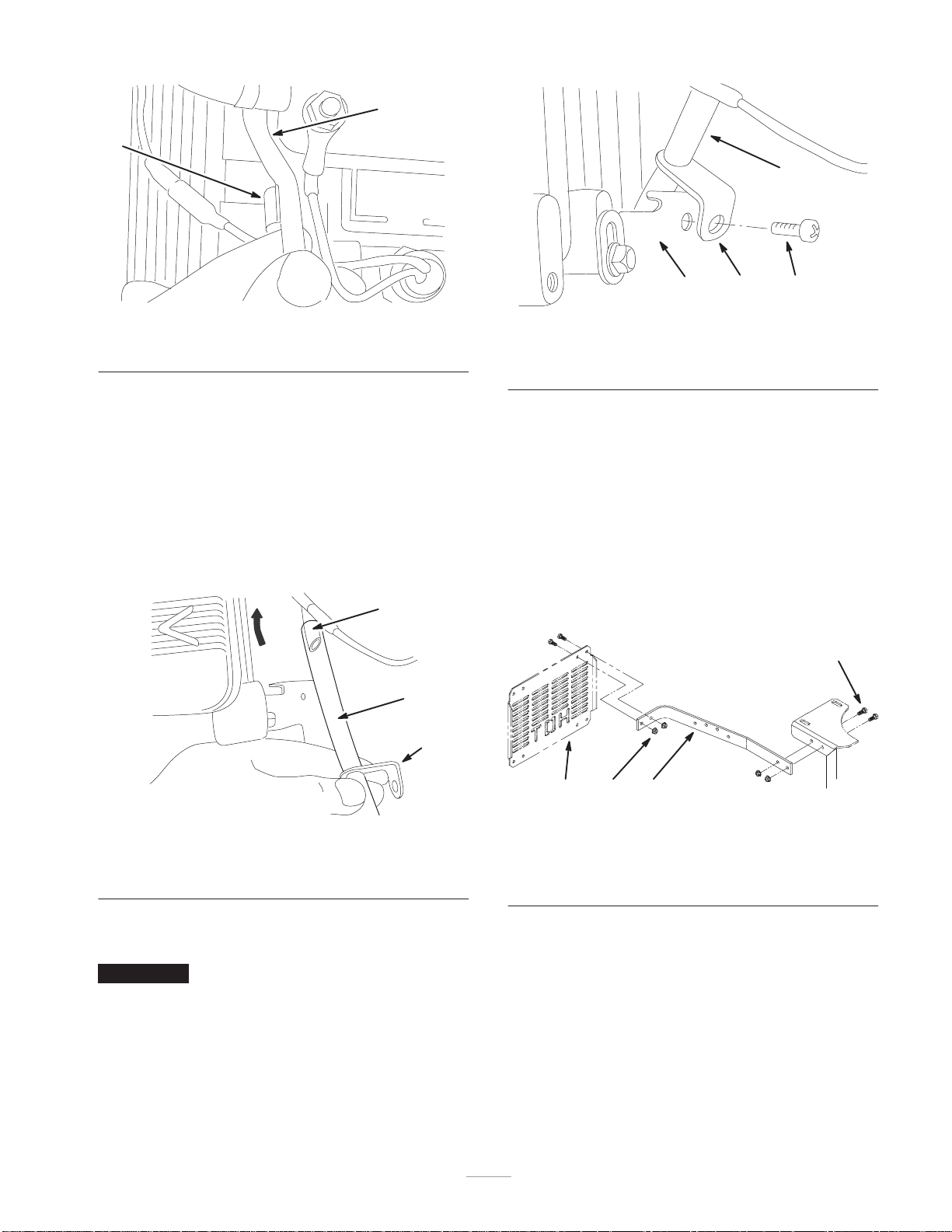
Installing the Left–hand Guard
Strap
1. Remove the existing left–hand guard strap. Save
hardware to install new strap
2. Install new guard strap to heat shield and frame
(Fig. 13). Use hardware removed in step one to install
new guard strap.
1
2
3
m–5858
Figure 11
1. Existing vent tube
2. New vent tube
3. Bracket
6. Fasten bracket to the control panel with screw
(Fig. 12).
Important Check to be sure vent tube is not restricted
or pinched.
3
4
2
1
m–5845
Figure 13
1. Left–hand strap
2. Heat shield
3. Bolts
4. Nuts
Drilling Holes for Guards
Drilling Hole for the Left Guard
1. With the left guard strap in place, install the left guard
to the left guard strap. Use 2 bolts (5/16 x 3/4 in.) and
2 nuts (5/16 in.) (Fig. 14).
5
 Loading...