

Page 1
Brake Service Kit
2001 Domestic T-Bar Gear-Drive Mid-Size Mowers
Model No. 105-4654
Installation Instructions
Loose Parts
Note: Use the chart below to identify parts for assembly.
DESCRIPTION QTY. USE
Form No. 3350-770
Template No. 1, Lefthand
Template No. 2, Righthand
Brake Plate Link
Brake Link
Retaining Ring, 3/8 inch
Retaining Ring, 5/16 inch
Brake Arm
Brake Mounting Hub
Flange Nut, 3/8 inch
Flat Washer
Screw, 3/8 x 1-3/4 inch
Cotter Pin
Decal
Important
and right brakes.
This kit needs to be installed on both left
1
1
2
2
2
4
2
2
2
4
2
2
2
Drilling Holes for Brakes
Installing the Brake Links
Installing the Brakes
Removing Existing Brakes
Warning
105–4661
2003 by The Toro Company
8111 Lyndale Avenue South
Bloomington, MN 55420-1196
Mechanical or hydraulic jacks may fail to support
machine and cause a serious injury.
• Use jack stand when supporting machine.
• Do not use hydraulic jacks.
Removing the Wheel Hub
1. Disengage the power take off (PTO), set the parking
brake, and turn the ignition key to off. Remove the key.
2. Raise the rear of the machine onto jack stands high
enough to raise the drive wheels off of the ground.
3. Remove the left and right drive tires (Fig. 2).
4. Disengage the parking brake.
Original Instructions (EN)
Contact us at www.Toro.com
All Rights Reserved
Printed in the USA
Page 2
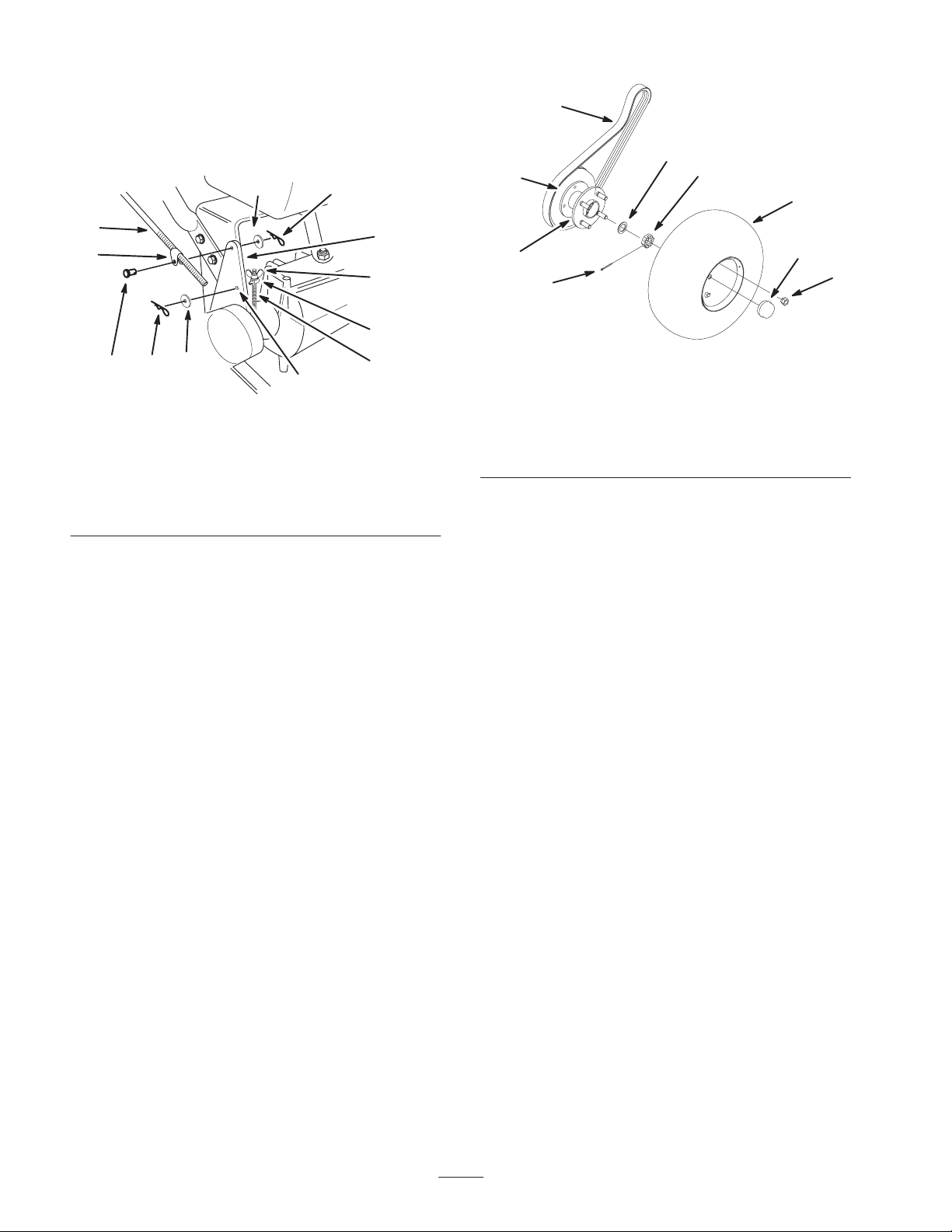
5. Disconnect the left and right brake rods from the brake
arms (Fig. 1).
6. Disconnect the left and right control rods and brake
rods from the idler brackets (Fig. 1).
6
1
6
4
5
2
7
9
3
7
4
2
8
6
1
5
10
m–5316
Figure 1
1. Hairpin cotter
2. Trunnion
3. Idler bracket
4. Wing nut
5. Hole F
6. Washer
7. Rod fitting
8. Clevis pin
9. Control rod
10. Brake rod
7. Remove the traction belts from the double pulleys
attached to the wheel hubs (Fig. 2). Move them to the
rear over the traction drive pulley.
Note: Do not remove the belts completely from the
machine.
8. Remove the hub dust caps (Fig. 2).
9. Remove the cotter pins from axle nuts, axle nuts, spacer
washers (if used) and wheel hub assemblies (Fig. 2).
Note: Do not get grease on brake band and brake drum.
Cover the wheel hubs to avoid getting dirt into them.
1
8
3
m–5550
Figure 2
1. Wheel hub assembly
2. Axle nut
3. Cotter pin
4. Spacer (if used)
5. Double pulley
6. Traction belt
7. Tire
8. Hub dust cap
9. Nut
Removing the Brake Bands
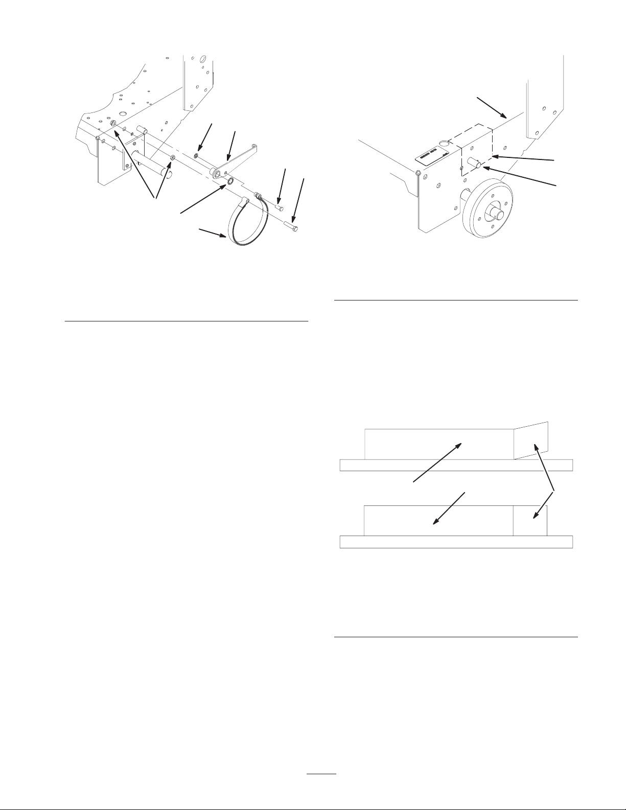
1. Remove the retaining rings holding brake arms to
frame. Discard retaining rings (Fig. 3).
2. Remove the brake band bolts from the frame by
removing the nuts on the inside of the frame (Fig. 3).
3. Remove the brake band and brake arm assemblies from
the machine (Fig. 3).
4. Remove the bolts and nuts from the brake bands. These
nuts and bolts can be discarded (Fig. 3).
5. Remove the clevis pins and retaining rings holding the
brake bands to brake arms. The clevis pins, retaining
rings and brake arms can be discarded.
9
2
Page 3
3
6
1
5
4
6
2
m–5551
Figure 3
1. Brake arm (Left hand
shown)
2. Brake band
3. Bolt
4. Nuts
5. Clevis pin
6. Retaining ring
Drilling Holes for Brakes
1. Locate and cut out templates number 1 (lefthand) and
number 2 (righthand) as indicated on the templates.
Fold the templates on the indicated fold line.
Note: Make sure the circle is cut out on both templates.
2. Slide template number 1 (lefthand) onto the brake pivot
pin and place the fold onto frame. The fold must match
up with the corner of the frame. Tape the template in
this position (Fig. 4).
1
3
2
m–5553
Figure 4
1. Template No. 1, Left side
(Use template No. 2 for
right side.)
2. Brake pivot pin
3. Corner of frame
Installing the Brake Links
Note: Brake band may need to be straightened.
1. Check to make sure brake band is straight. Lay band
onto table to see if it is bent (Fig. 5).
2. If needed, bend band so it is straight.
3. Center punch the hole that is needed to be drilled and
remove the template (Fig. 4).
Note: The hole location is very important.
4. Cut off the left brake pivot pin and grind flush with
frame. Do not damage side of frame.
5. Drill a 1/8 inch pilot hole into the frame at the punch
mark. Then drill a 25/64 inch into the 1/8 inch hole.
6. Apply paint to the side of the frame where the pivot pin
was removed.
7. Repeat these steps on the right side of the frame using
template number 2.
1
2
3
m–5569
Figure 5
1. Bent brake band, bend it
straight
2. Straight brake band,
correct position
3. Loop in band
3. Place a brake link assembly so the pins are pointing up
(Fig. 6).
4. Install the brake band onto the brake link assembly.
Install the band loops over the two 5/16 inch pins.
5. Install the new brake arm onto the 3/8 inch pin of the
brake link assembly.
6. Place the brake link plate onto the assembly (Fig. 6).
3
Page 4
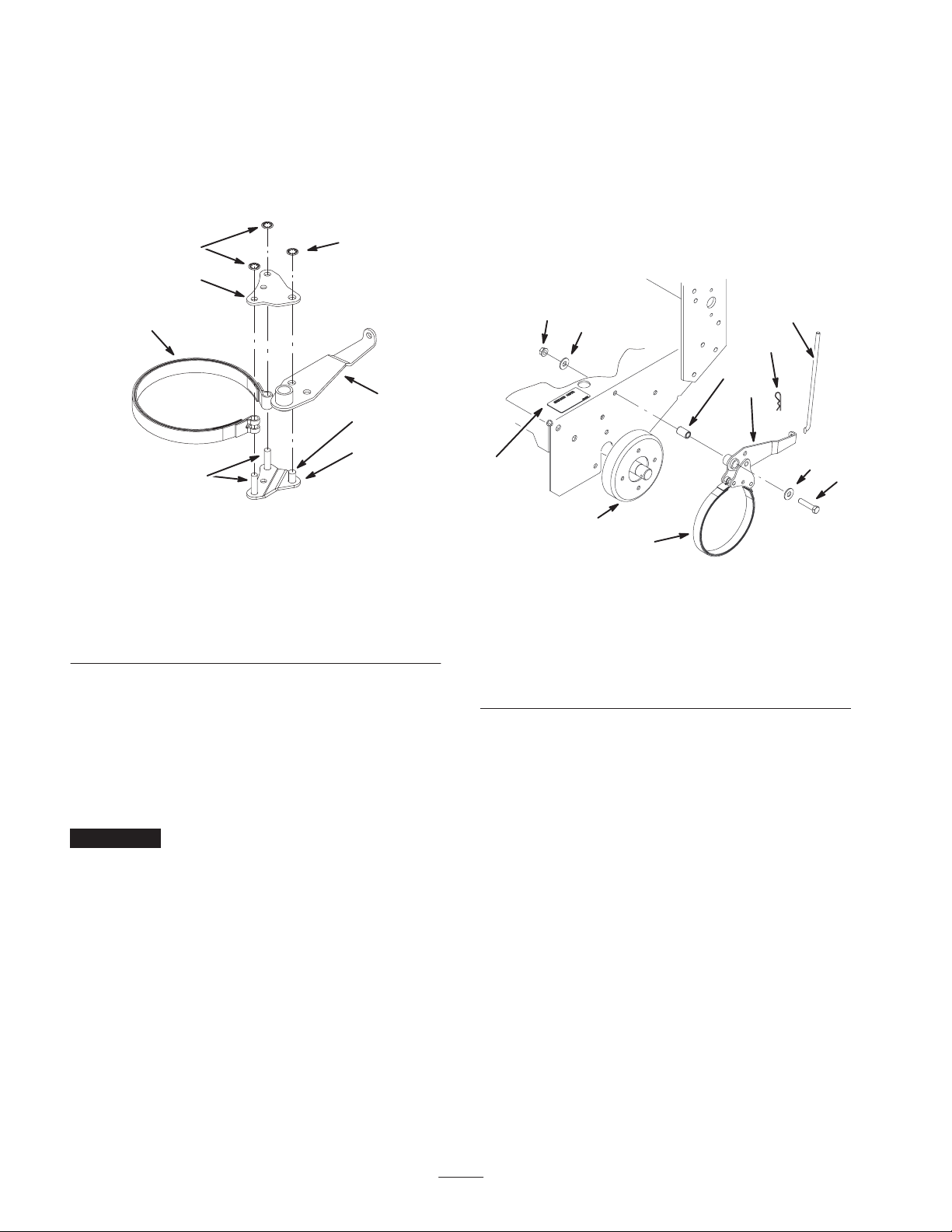
7. Install 2 retaining rings (5/16 inch) on each of the
5/16 inch pins. This will hold the ends of the brake band
on each assembly (Fig. 6).
8. Install a retaining ring (3/8 inch) on the 3/8 inch pin.
This will connect the brake arm to the link (Fig. 6).
9. Repeat these steps for the opposite side.
4
7
3
7. Install cotter pin into axle nut (Fig. 2).
Note: If notch in axle nut does not line up with hole in end
of axle, loosen nut slightly and install cotter pin.
8. Refill wheel hub with grease and install grease cap
(Fig. 2).
9. Install decal onto machine in the position shown in
figure 7.
10.Repeat these steps for the opposite side.
2
8
6
1
5
m–7114
Figure 6
Left Side Brake Link Assembly
1. Brake link assembly
2. Brake band
3. Brake link plate
4. Retaining rings, 5/16 inch
5. 5/16 inch pins
6. 3/8 inch pin
7. Retaining ring, 3/8 inch
8. Brake arm (Left hand
shown)
Installing the Brake
1. Place washer onto mounting bolt (3/8 x 1–3/4 inch)
(Fig. 7).
2. Lubricate the outside of brake mounting hub with
never–seize (Fig. 7).
Important Check to make sure the brake arm moves
freely on the brake mounting hub. If required remove any
excess paint from the brake arm.
3. Install the brake assembly to the machine using
mounting bolt, washers, brake mounting hub and flange
nut ( 3/8 inch) (Fig. 7). Tighten the bolt and nut to
30 ft–lbs (41 N⋅m).
4. Wipe any dirt or debris from the axle ends.
5. Place wheel hub assemblies onto axle while holding
brake bands in place (Fig. 2).
6. Reinstall spacer washers (when needed) and axle nuts
(Fig. 2). Tighten axle nut to 15 to 20 in–lbs. at the
maximum.
4
6
3
10
5
7
8
3
9
1
m–7115
Figure 7
1. Brake assembly
2. Mounting bolt
(3/8 x 1–3/4 inch)
3. Washer
4. Flange nut, 3/8 inch
5. Brake mounting hub
6. Brake rod
7. Brake arm
8. Decal
9. Brake drum
10. Hair pin cotter
Installing the Control Rods and
Brake Rods
1. Install traction belts onto pulleys.
2. Install brake rods to brake arms with hairpin cotters and
washers previously removed (Fig. 7).
3. Install brake rod trunions into idler bracket hole F with
washers and hairpin cotters previously removed
(Fig. 8).
4. Thread rod fittings equal distance onto each control rod.
For a starting point, thread fittings on approximately
1–3/4 inch (44 mm) from the start of the threads
(Fig. 8).
5. Slide clevis pins through rod fittings and mounting
holes in idler brackets (from outside) (Fig. 8). Secure
with washers and hairpin cotters (Fig. 8).
2
4
Page 5

7
6
1
Servicing the Brake
3
9
4
8
2
6
1
5
m–5316
Figure 8
1. Hairpin cotter
2. Trunnion
3. Idler bracket
4. Wing nut
5. Hole F
6. Washer
7. Rod fitting
8. Clevis pin
9. 1–3/4inch (44 mm)
6. Check the gap between upper control bar and fixed bar
with wheel drive fully engaged. Gap should be
approximately 1 to 1-1/4 inch (25-32 mm) (Fig. 9).
Note: The upper control bar and fixed bar must be parallel
when in engaged, drive, relaxed and brake positions.
7. Check operation. If adjustment is required, remove
hairpin cotter securing rod to upper control bar. Thread
rod in or out of fitting for proper position and install
into upper control bar with hairpin cotter.
5
4
2
3
1
Checking the Brake
1. Park the machine on a level surface, disengage the
power take off (PTO) and turn the ignition key to off.
Remove the key.
2. Set the parking brake (Fig. 10).
2
1
m–5233
Figure 10
1. Upper control bar 2. Parking brake lever (set
position)
3. Rear wheels must lock when you try to push the
machine forward. Adjustment is required if the wheels
turn and do not lock; refer to Adjusting the Brake.
4. Release the brake and press upper control bar very
lightly, approximately 1/2 inch (13 mm), wheels should
rotate freely.
5. If both conditions are met no adjustment is required.
Adjusting the Brake
The parking brake lever is on the upper control bar (Fig.
10). If the parking brake does not hold securely, an
adjustment is required.
1. Check the brake before you adjust it; refer to Checking
the Brake, page 5.
Figure 9
1. Control rod
2. Fixed control bar
3. Parking brake lever
4. Upper control bar
5. 1 to 1–1/4 inch gap
8. Install rear wheels (Fig. 2).
9. Remove machine from jack stands.
10.Check brake operation and proceed to Servicing the
Brake.
m–5190
2. Release the parking brake.
3. To adjust the brake remove the hairpin cotter and
washer from the trunion. Remove trunion from the idler
bracket (Fig. 11).
4. Rotate the wingnut clockwise to increase the brake
force or counter clockwise to reduce the brake force
(Fig. 11).
5. Secure trunnion to idler bracket with washer and cotter
pin (Fig. 11).
6. Check the brake operation again; refer to Checking the
Brake.
5
Page 6

Important With the parking brake released, the rear
wheels must rotate freely when you push the mower. If
brake action and free wheel rotation cannot be achieved
contact your service dealer immediately.
3
4
2
1
Figure 11
1. Hairpin cotter and washer
2. Trunnion
3. Idler bracket
5
4. Wing nut
5. Hole F
m–5316
6
Page 7

Template No. 1
Fold 90 Degrees Along this Line
Drill a 25/64 inch
hole here.
Cut out circle
here.
Template No. 1
UP
Cut
Out
Cut out template here
Left
Hand
FRONT
7
Page 8

8
Page 9

Template No. 2
Template No. 2
Fold 90 Degrees Along this Line
Drill a 25/64 inch
hole here.
Cut out circle
here.
UP
Cut
Out
Right
Hand
FRONT
Cut out template here
m–5554
9
Page 10

10
Page 11

11
Page 12

 Loading...