

Page 1
Form No. 3326-609
Electric Starter Kit
For CCR 2000 and CCR 3000 Snowthrowers
Serial Nos. 7000001 and Up
Part Nos. 84-5291, 84-5292,
Warning
Installing the new starter improperly may result
in an electric shock or even death when operating
the starter.
• Have a Toro Master Service Dealer or an
Authorized Service Dealer with a high potential
tester to perform a high potential test on the
new starter before using it for the first time.
• If you are uncomfortable installing the starter
kit, have a Toro Master Service Dealer or an
Authorized Service Dealer with a high potential
tester to install the kit.
Removing the Old Starter
105-2955, and 105-2956
1
Installation
Instructions
4
3
2
7
8
5
6
9
m2837
1. Stop the engine and wait for all moving parts to stop.
2. Remove the key from the switch.
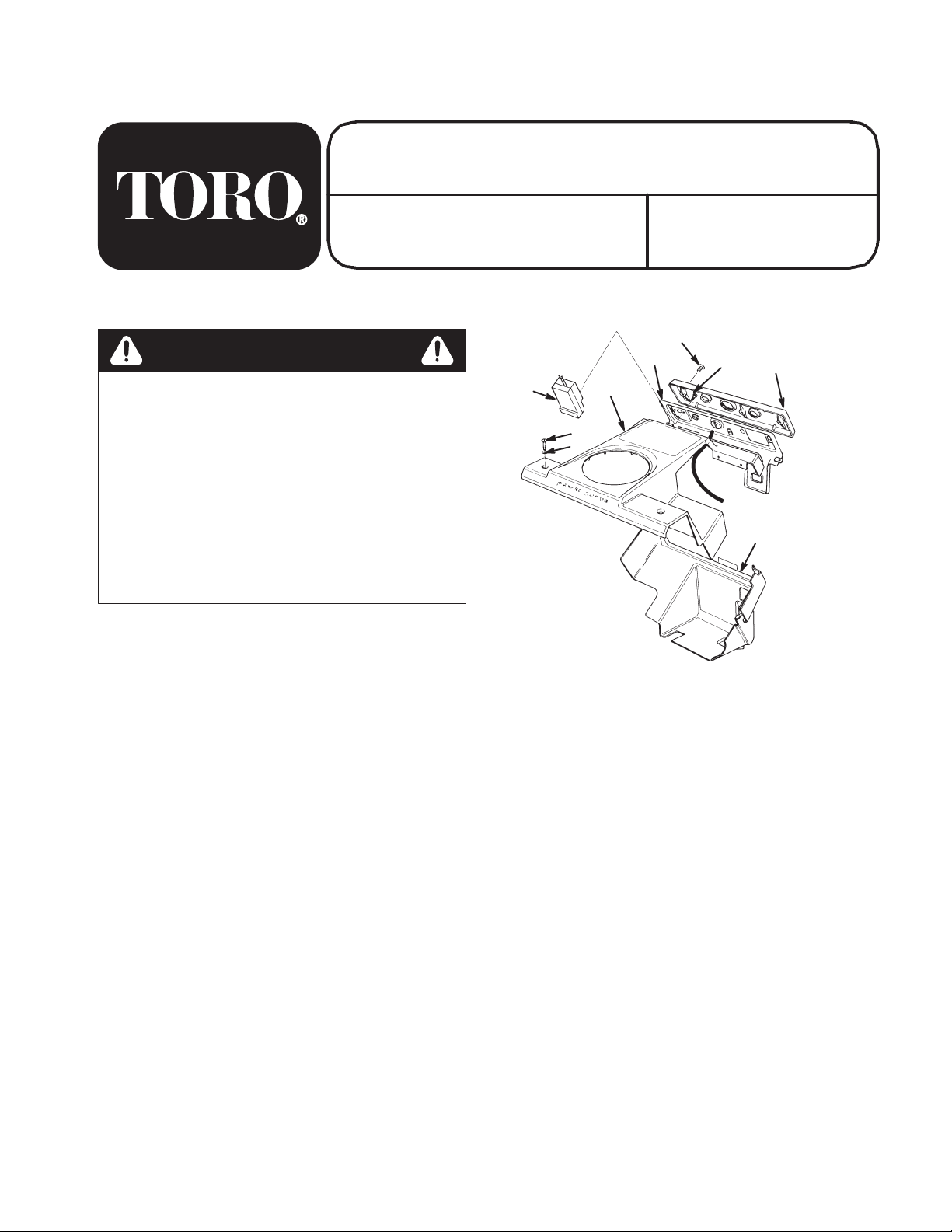
3. Remove the 3 short self-tapping screws, and remove
the control nameplate from the control panel (Fig. 1).
Figure 1
1. Switch assembly
2. Upper shroud assembly
3. Control panel
4. Short self-tapping
screw (3)
5. Long self-tapping
screw (3)
6. Control nameplate
7. Phillips screw (2)
8. Flat washer (4)
9. Lower shroud
Note: You can leave the control nameplate on the
starter rope.
4. Disconnect the wire from the spark plug.
5. Remove the fuel tank cap and use a hand pump to
pump the fuel into an approved fuel container.
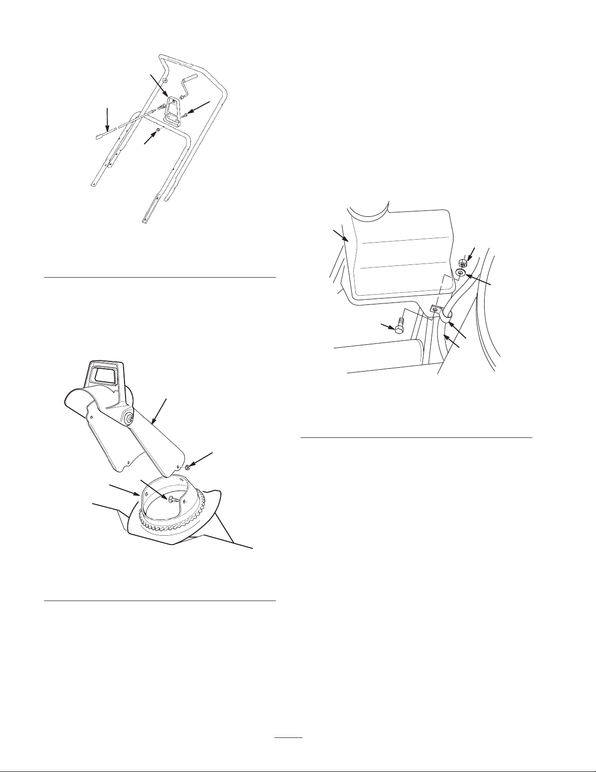
Removing the Chute Crank Assembly
Remove the 2 hex-head bolts and locknuts that hold the
chute crank support to the lower handle, and remove the
chute crank assembly from the handle (Fig. 2).
2001 The Toro Company
All Rights Reserved
1
Printed in USA
Page 2
2. Remove the 2 hex-head bolts and curved washers, and
1
remove the lower shroud and control panel from the
lower handle (Fig. 1).
3
2
4
m2835
Figure 2
1. Chute crank support
2. Hex-head bolt (2)
3. Chute crank assembly
4. Locknut (2)
Removing the Discharge Chute
Remove the 3 carriage bolts and locknuts that hold the
discharge chute to the chute gear ring, and remove the
discharge chute from the chute gear ring (Fig. 3).
3. Remove the 3 long self-tapping screws, and remove
the switch assembly and attached starter wires from
the control panel (Fig. 1).
4. Remove the hex-head bolt, the flat washer, and the
locknut, and remove the R-clamp from the starter
wires (Fig. 4).
5. Slide the bottom cover from under the axle and hold it
out of the way.
1
2
3
4
5
6
m2838
1
2
4
3
m2836
Figure 3
1. Discharge chute
2. Locknut (3)
3. Carriage bolt (3)
4. Chute gear ring
Removing the Shrouds, Control Panel,
and Switch Assembly
1. Remove the 2 Phillips screws, 4 flat washers, and 2
locknuts that hold the upper shroud assembly to the
frame, and remove the upper shroud assembly (Fig. 1).
Figure 4
1. Fuel tank
2. Locknut
3. Flat washer
4. Hex-head bolt
5. R-clamp
6. Starter wires
Removing the Old Starter Motor
1. Remove the upper starter motor mounting bolt
(Fig. 5).
2
Page 3

1
1
2
m2839
Figure 5
1. Upper starter motor
mounting bolt
2. Starter motor
2. Carefully tip the snowthrower upside down.
3. Pull the bottom cover down below the axle and
remove the lower starter motor mounting bolt (Fig. 6).
1
3
2
4
5
6
Figure 6
1. Starter motor
2. Lower starter motor
mounting bolt
3. Housing mount
4. Pinion stop
5. Pinion cup
6. Bottom cover (shown
down)
m2840
2
7
3
8
4
5
6
m2841
Figure 7
1. Switch housing cover
2. Outer insulation
3. Switch wire
4. Screw boss
5. Switch housing base
6. Locking tab (2)
7. Switch
8. AC connector
2. Pull the switch and the AC connector out of the switch
housing base (Fig. 7).
3. Insert the smooth end of a small drill bit into the
switch contact openings, depress the flat springs inside
the contact openings, and pull the old starter wires out
of the switch (Fig. 8).
1
2
3
4
4. Slide the starter motor away from the pinion cup, and
remove the starter motor and the attached switch
assembly from the snowthrower (Fig. 6).
Installing the New Starter
Installing the New Wiring
Parts 84-5291 and 84-5292 only
1. Push in the locking tabs and separate the switch
housing cover from the switch housing base (Fig. 7).
To motor
1. Starter wire
2. Contact opening
3
To plug
m2842
Figure 8
3. Smooth end of drill bit
4. Switch
Page 4

4. Twist the new starter wires and insert them all the way
into the contact openings (Fig. 8).
5. Install the switch, the switch wires, and the AC
connector into the switch housing base.
Note: Ensure that the slots in the AC connector fit into
the matching cutout in the base (Fig. 7).
6. Route the starter wires between the switch and the
inside of the screw boss, then out through the serrated
cord opening in the switch housing base (Figs. 7
and 9).
7. Carefully push the starter wires down between the
switch and the screw boss with a blunt object (Figs. 7
and 9).
Important Be careful not to pinch your finger in the
pinion stop or pinion cup when you install the new starter
motor.
3. Install and tighten the upper and lower starter motor
mounting bolts (Figs. 5 and 6).
4. Install the bottom cover back into its original position
above the axle (Fig. 6).
Mounting the Switch Assembly, Control
Panel, and the Shrouds
1. Return the snowthrower to its upright position.
2. Install the R-clamp onto the new starter wires (Fig. 4).
Important Route the starter wires between the switch
and the inside of the screw boss in the switch housing
base. This prevents the screw from cutting into the
insulation and/or wires when you install the switch
assembly to the control panel.
8. Ensure that the end of the outer insulation is at least
3/16 in. (5 mm) from the inside edge of the serrated
cord opening in the switch housing base (Fig. 9).
12
3
4
7
5
6
m2851
Figure 9
1. Inside edge of serrated
cord opening
2. End of outer insulation
3. 3/16 in. (5 mm) minimum
4. Screw boss
5. Switch wires
6. Switch housing base
7. Switch
3. Fasten the R-clamp and the attached wires to the fuel
tank tab with the hex-head bolt, the flat washer, and
the locknut (Fig. 4).
4. Route the starter wires over the top of the fuel tank
and install the switch assembly to the control panel
with the 3 long self-tapping screws (Fig. 1).
5. Fasten the lower shroud and the control panel to the
lower handle with the 2 hex-head screws and curved
washers (Fig. 1).
6. Fasten the upper shroud assembly to the frame with
the 2 Phillips screws, 4 flat washers, and 2 locknuts
(Fig. 1).
Installing the Discharge Chute
Fasten the discharge chute to the chute gear ring using the
3 carriage bolts and locknuts (Fig. 3).
Installing the Chute Crank Assembly
1. Insert the chute crank assembly through the hole in the
upper shroud, ensuring that the end of the crank
assembly seats correctly in the face gear (Fig. 2).
2. Fasten the chute crank support to the lower handle
with 2 hex-head bolts and locknuts (Fig. 2).
9. Snap the switch housing cover back onto the switch
housing base (Fig. 7).
Installing the New Starter Motor
1. Hold the bottom cover down and insert the new starter
motor up through the frame.
Note: Position the motor so that the housing mount
contacts the mating surfaces on the engine.
2. Push gently on the pinion stop as necessary and insert
the pinion into the pinion cup (Fig. 6).
Completing the Installation
1. Install the fuel tank cap.
2. Connect the wire to the spark plug.
3. Install the control nameplate onto the control panel
(Fig. 1).
Note: Ensure that the control nameplate fits over the
flanges on the upper and lower shrouds, then install
and tighten the control nameplate with 3 short
self-tapping screws.
4. Insert the key in the switch.
4
 Loading...