Toro 105-2956, 105-2955, 84-5291, 84-5292 Installation Instructions

Form No. 3326-609
Electric Starter Kit
For CCR 2000 and CCR 3000 Snowthrowers
Serial Nos. 7000001 and Up
Part Nos. 84-5291, 84-5292,
105-2955, and 105-2956
Installation
Instructions
Warning
Installing the new starter improperly may result in an electric shock or even death when operating the starter.
•Have a Toro Master Service Dealer or an Authorized Service Dealer with a high potential tester to perform a high potential test on the new starter before using it for the first time.
•If you are uncomfortable installing the starter kit, have a Toro Master Service Dealer or an Authorized Service Dealer with a high potential tester to install the kit.
Removing the Old Starter
1.Stop the engine and wait for all moving parts to stop.
2.Remove the key from the switch.
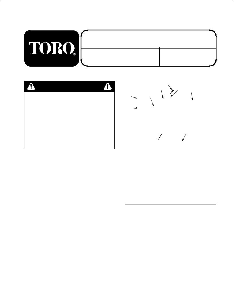
3.Remove the 3 short self-tapping screws, and remove the control nameplate from the control panel (Fig. 1).
5 6
 7
7  8
8
9
Figure 1
1. |
Switch assembly |
6. |
Control nameplate |
2. |
Upper shroud assembly |
7. |
Phillips screw (2) |
3. |
Control panel |
8. |
Flat washer (4) |
4. |
Short self-tapping |
9. |
Lower shroud |
|
screw (3) |
|
|
5.Long self-tapping screw (3)
Note: You can leave the control nameplate on the starter rope.
4. Disconnect the wire from the spark plug.
5. Remove the fuel tank cap and use a hand pump to pump the fuel into an approved fuel container.
Removing the Chute Crank Assembly
Remove the 2 hex-head bolts and locknuts that hold the chute crank support to the lower handle, and remove the chute crank assembly from the handle (Fig. 2).
2001 The Toro Company
All Rights Reserved
1 |
Printed in USA |

1
3 |
2 |
|
4
|
|
|
m 2835 |
|
|
Figure 2 |
|
1. |
Chute crank support |
3. |
Chute crank assembly |
2. |
Hex-head bolt (2) |
4. |
Locknut (2) |
|
|
|
|
Removing the Discharge Chute
Remove the 3 carriage bolts and locknuts that hold the discharge chute to the chute gear ring, and remove the discharge chute from the chute gear ring (Fig. 3).
1
2
3
4
m 2836
Figure 3
1. |
Discharge chute |
3. |
Carriage bolt (3) |
2. |
Locknut (3) |
4. |
Chute gear ring |
|
|
|
|
Removing the Shrouds, Control Panel,
and Switch Assembly
1.Remove the 2 Phillips screws, 4 flat washers, and 2 locknuts that hold the upper shroud assembly to the frame, and remove the upper shroud assembly (Fig. 1).
2.Remove the 2 hex-head bolts and curved washers, and remove the lower shroud and control panel from the lower handle (Fig. 1).
3.Remove the 3 long self-tapping screws, and remove the switch assembly and attached starter wires from the control panel (Fig. 1).
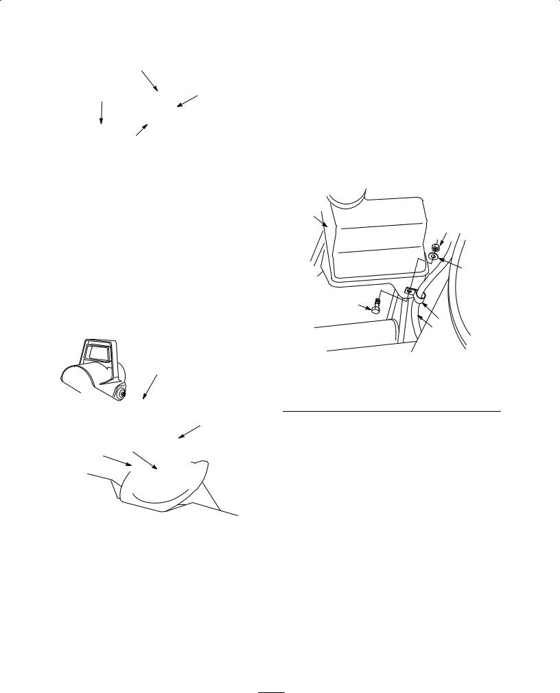
4.Remove the hex-head bolt, the flat washer, and the locknut, and remove the R-clamp from the starter wires (Fig. 4).
5.Slide the bottom cover from under the axle and hold it out of the way.
1
|
|
|
2 |
|
|
|
3 |
|
|
4 |
|
|
|
|
5 |
|
|
|
6 |
|
|
|
m 2838 |
|
|
Figure 4 |
|
1. |
Fuel tank |
4. |
Hex-head bolt |
2. |
Locknut |
5. |
R-clamp |
3. |
Flat washer |
6. |
Starter wires |
Removing the Old Starter Motor
1.Remove the upper starter motor mounting bolt (Fig. 5).
2
 Loading...