


FORM NO. 3326–318 Rev A
Z–Stand Kit
Z–Master 100 Series
Part No. 105–1621
Safety and Instruction Decals
Safety decals and instructions are easily visible to the operator and are located near any
area of potential danger. Replace any decal that is damaged or lost.
Part No. 104–7759
Loose Parts
INSTALLATION
INSTRUCTIONS
Note: Use the chart below to identify parts for assembly.
DESCRIPTION QTY. USE
Z–Stand hub
Bracket latch
Bolt, 3/8 x 1–1/2 in.
Lock nut, 3/8 in.
Z–Stand hub
Bolt, 3/8 x 3–1/2 in.
Lock nut, 3/8 in.
Hair Pin cotter
Clevis pin, 3 in.
Clevis pin, 2–5/8 in.
1
1
Assemble 100 Series Z–Stand hub
1
1
1
2
2
Install 100 Series Z–Stand hub
2
1
1
The Toro Company – 2002
Printed in USA
All Rights Reserved
Installation Instructions
DESCRIPTION USEQTY.
Z–Stand foot
Z–Stand tube
Thrust washers
Lynch pin
Hair pin cotter
Clevis pin
Z–Stand bracket
Bolt, 5/16 x 2–3/4 in.
Lock Nut, 5/16 in.
Bolt, 1/4 x 3/4 in.
Lock Nut, 1/4 in.
Lanyard
The following instructions are for installing the
Z–Stand on a 100 Series Z–Master.
Assemble 100 Series Z–Stand
1
1
2
Install 100 Series Z–Stand
1
2
2
1
1
1
Install 100 Z–Stand bracket
1
1
1
2
4
Hub
1. Install the bracket latch to the Z–Stand hub with
a bolt (3/8 x 1–1/2 in.) and lock nut (3/8 in.)
(Fig. 1).
Note: Tighten the nut and bolt. Then,
unscrew it one full turn or until the
latch will freely rotate (Fig. 1).
1
m–5357
1. Bracket latch
2. Z–Stand hub
Figure 1
3. Bolt, 3/8 x 1–1/2 in.
4. Lock Nut, 3/8 in.
3
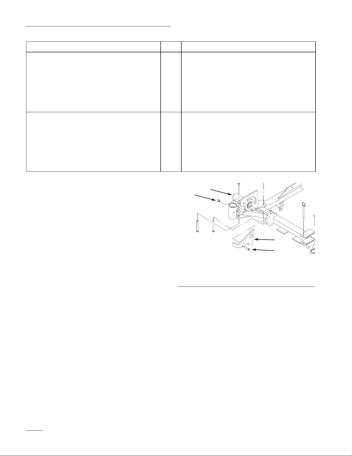
Install 100 Series Z–Stand Hub
1. Place the Z–Stand hub on the right front frame
as shown in figure 2.
Note: Make sure the Z–Stand hub assembly
is against the front caster housing.
2. Install Z–Stand hub to frame with 2 bolts
3/8 x 3–1/2 in.) and 2 lock nuts (3/8 in.) (Fig. 2).
(
Note: Install bolts as shown in figure 2.
2
Installation Instructions
1
2 4
4
3
m–5357
Figure 2
1. Right front frame
2. Z–Stand hub assembly
3. Bolt, 3/8 x 3–1/2 in.
4. Lock Nut, 3/8 in.
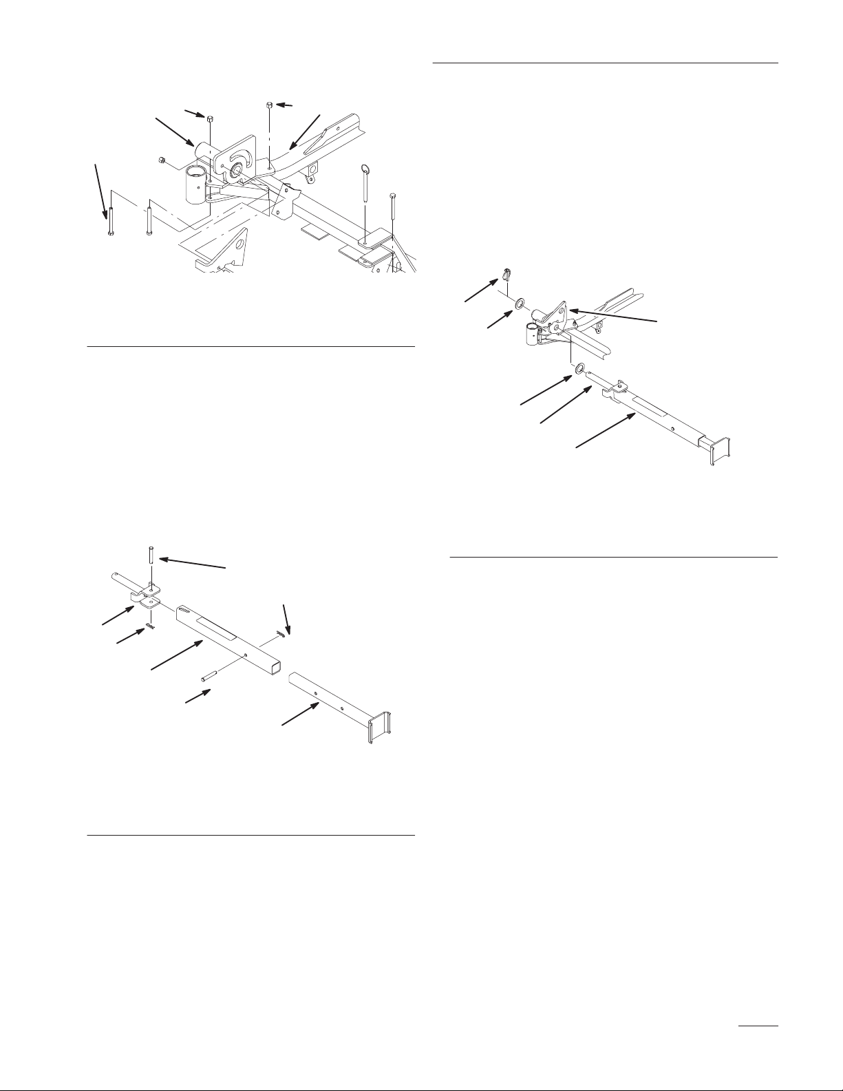
Install 100 Series Z–Stand
1. Place the foot part of stand into the Z–Stand
tube. Align holes and secure with a clevis pin
(2–5/8 in.) and hair pin cotter (Fig. 3).
2. Install Z–Stand assembly to the pivot pin with a
clevis pin (3 in.) and hair pin cotter (Fig. 3).
4. Insert pivot pin into the Z–Stand hub as shown
in figure 4.
Note: When inserting the pivot pin, make
sure the position of slot in tube is as
shown in figure 3.
5. Place a thrust washer onto the pivot pin and
secure with a lynch pin (Fig. 4).
5
3
4
4
2
1. Z–Stand
2. Pivot Pin
3. Z–Stand hub
1
Figure 4
4. Thrust washer
5. Lynch pin
m–5358
3
4
2
4
1
6
m–5359
5
Figure 3
1. Z–Stand tube
2. Pivot Pin
3. Clevis Pin, 3 in.
4. Hair pin cotter
5. Z–Stand foot
6. Clevis Pin, 2–5/8 in.
3. Place a thrust washer onto the pivot pin (Fig. 4).
Install 100 Series Z–Stand
Bracket
1. Place the Z–Stand bracket on the left front frame
as shown in figure 5.
2. Install Z–Stand bracket with a bolt
(5/16 x 3–1/4 in.) and lock nut (5/16 in.)
(Fig. 5).
Note: Install bolt as shown in figure 5.
3. Install lanyard to bracket pin. Use large loop on
lanyard (Fig. 5).
4. Install lanyard with a bolt (1/4 x 3/4 in.) and
lock nut (1/4 in.) (Fig. 5).
3

Installation Instructions
8
7
4
5
2
6
1
3
m–5357
Figure 5
1. Left front caster housing
2. Z–Stand bracket
3. Bolt, 5/16 x 3–1/4 in.
4. Lock Nut, 5/16 in.
Using the Z–Stand
5. Lock Nut, 1/4 in.
6. Bolt, 1/4 x 3/4 in.
7. Lanyard
8. Bracket Pin
The Z–Stand is used for raising the front end of the
machine. This allows for cleaning of the deck and
removal of the blades.
4
2
5
1
3
m–5375
Figure 6
1. Z–Stand
2. Latch
3. Bracket
4. Bracket Pin
5. Bottom of slot
3. Raise latch. Swing stand foot out front and slide stand
toward machine, into the bottom of slot (Fig. 6 and 8).
4. Remove the cotter hair pin and clevis pin (Fig. 7).
5. Pull out the foot part of stand and insert clevis pins and
cotter hair pins (Fig. 7).
2
Warning
Unit could fall onto someone and cause serious
injury or death.
• Use extreme caution when operating unit
on Z–Stand.
• Use only for cleaning deck and removing
blades.
• Do not keep unit on Z–Stand for extended
periods of time.
• Always shut engine off and set parking
brake before performing any maintenance
to deck.
Driving up onto the Z–Stand
1. Raise deck to transport position.
2. Remove bracket pin (Fig. 6).
1
3
m–5380
Figure 7
1. Clevis Pin
2. Hair pin cotter
3. Z–Stand foot
6. Set foot of stand on the ground and rest latch on pivot
tab (Fig. 8).
7. Start engine and put at half throttle.
Note: For best results, place foot of stand
into seams in sidewalks or into turf
(Fig. 8).
4

Installation Instructions
3
1
2
m–5374
Figure 8
1. Z–Stand (Positioned in
slot)
2. Crack in side walk or turf
3. Latch resting on pivot tab
8. Drive onto stand. Stop when latch drops over tab into
locked position (Fig. 9). Once onto stand, engage
parking brake. Shut off engine.
9. Chock or block the drive wheels.
Warning
Parking brake may not hold machine parked on
Z–Stand and could cause personal injury or
property damage.
4
2
1
1. Z–Stand
2. Latch
3
m–5373
Figure 9
3. Locked position
4. Unlocked position
Do not park on Z–Stand unless wheels are
chocked or blocked.
10.Perform maintenance.
11. Remove chocks or blocks.
Driving off the Z–Stand
1. Raise latch to unlocked position (Fig. 9).
2. Start engine and place at half throttle. Disengage
parking brake.
3. Slowly drive backwards off of stand.
4. Remove the cotter hair pins and stand pins (Fig. 7).
5. Push in the inner part of stand and insert stand pins
and cotter hair pins (Fig. 7).
6. Return stand to its rest position (Fig. 6).
7. Insert bracket pin into Z–Stand bracket (Fig. 6).
5

Installation Instructions
6

Installation Instructions
7

Installation Instructions
8
 Loading...