

Toro 105-1383 Parts Catalogue

Form No. 3325–913
Hydrostatic Transaxle Replacement
Kit
260 Series Yard and Garden Tractor
Part No. 105–1383
Parts Catalog
Ordering Replacement Parts
To order replacement parts, please supply: the part
number, the quantity, and the description of each
part desired.
Understanding Reference Numbers
Each identified part in an illustration has a reference
number. The reference number for a part also appears in
the parts list, along with other information about the part.
This catalog uses two special reference number formats,
one to indicate parts in a service assembly and another
to indicate the quantity of a given part in an illustration.
Service Assembly Reference Numbers
Parts in service assemblies have reference numbers in
the form a:b.
the entire service assembly and the b represents a
sequential number unique to each part within the service
assembly.
The a represents the reference number of
The TORO Company — 2001
All Rights Reserved
For example, a wheel assembly might be identified by
reference number 6, the tire by 6:1, the valve by 6:2,
and the wheel by 6:3. When you order the assembly
identified by reference number 6, you receive all parts
identified by reference numbers 6:1, 6:2, and 6:3.
However, you may also order any part individually.
Reference numbers of this type appear in illustrations
and in part lists.
Reference Numbers Indicating Quantity
In an illustration, if a reference number indicates more
than one part, the reference number has the form nX y.
The n represents the quantity of the part, the X is the
multiplication symbol, and the y represents the reference
number.
For example, in an illustration, the reference number
2X 37 means that two of the parts identified by reference
number 37 are indicated.

3325–913
Contents
Description Page Description Page
Transaxle Fan and Pulley Assembly 3. . . . . . . . . . .
Transaxle Case Assembly 4. . . . . . . . . . . . . . . . . . . .
Center Case Assembly 5. . . . . . . . . . . . . . . . . . . . . . .
Cylinder Block Assembly 6. . . . . . . . . . . . . . . . . . . . .
Motor Shaft Assembly 7. . . . . . . . . . . . . . . . . . . . . . .
Charge Pump Assembly 8. . . . . . . . . . . . . . . . . . . . .
Bypass Shaft and Block Assembly 9. . . . . . . . . . . . .
Valve Arm Release Assembly 10. . . . . . . . . . . . . . . .
Shock Absorber Assembly 11. . . . . . . . . . . . . . . . . . .
Fulcrum and Shaft Assembly 12. . . . . . . . . . . . . . . .
Brake Assembly 13. . . . . . . . . . . . . . . . . . . . . . . . . . .
Differential Gear Assembly 14. . . . . . . . . . . . . . . . . .
Gear and Pinion Shaft Assembly 15. . . . . . . . . . . . .
Axle Shaft Assembly 16. . . . . . . . . . . . . . . . . . . . . . . .
Brake Band and Drum Assembly 17. . . . . . . . . . . . .
Maintenance 18–19. . . . . . . . . . . . . . . . . . . . . . . . . . . .
Part Description Abbreviations
Part descriptions in this catalog may include the following abbreviations.
Abbreviation Meaning Abbreviation Meaning
AR as required. . . . . . . . . . . . . . . . .
ASM assembly. . . . . . . . . . . . . . . .
CARR carriage. . . . . . . . . . . . . .
DEG degrees. . . . . . . . . . . . . . . .
FH flat head. . . . . . . . . . . . . . . . .
GA gauge. . . . . . . . . . . . . . . . .
HF hex flange. . . . . . . . . . . . . . . . .
HH hex head. . . . . . . . . . . . . . . . .
HHF hex head flange. . . . . . . . . . . . . . . .
HLH hex lag head. . . . . . . . . . . . . . . .
HJ hex jam. . . . . . . . . . . . . . . . . .
HOC height-of-cut. . . . . . . . . . . . . . . .
HS hex socket. . . . . . . . . . . . . . . . .
HSBH hex socket button head. . . . . . . . . . . . . .
HSFH hex socket flat head. . . . . . . . . . . . . . .
HSH hex socket head. . . . . . . . . . . . . . . .
HWH hex washer head. . . . . . . . . . . . . . .
HWHTF hex washer head. . . . . . . . . . . . .
thread forming
HYD hydraulic. . . . . . . . . . . . . . . .
INC incorporated. . . . . . . . . . . . . . . . .
LH left hand. . . . . . . . . . . . . . . . .
NI nylon insert. . . . . . . . . . . . . . . . . .
PPH Phillips pan head. . . . . . . . . . . . . . . .
PTH Phillips truss head. . . . . . . . . . . . . . . .
PTO power take off. . . . . . . . . . . . . . . .
RH right hand. . . . . . . . . . . . . . . . .
SFH slotted fillister head. . . . . . . . . . . . . . . .
SHH slotted hex head. . . . . . . . . . . . . . . .
SQH square head. . . . . . . . . . . . . . . .
SHWH slotted hex washer head. . . . . . . . . . . . . .
SPH slotted pan head. . . . . . . . . . . . . . . .
SRH slotted round head. . . . . . . . . . . . . . . .
STD standard. . . . . . . . . . . . . . . .
TAP self tapping. . . . . . . . . . . . . . . .
TTH Torx truss head. . . . . . . . . . . . . . . .
WH wing head. . . . . . . . . . . . . . . . .
2
3325–913
1
2
3
4
5
6
7
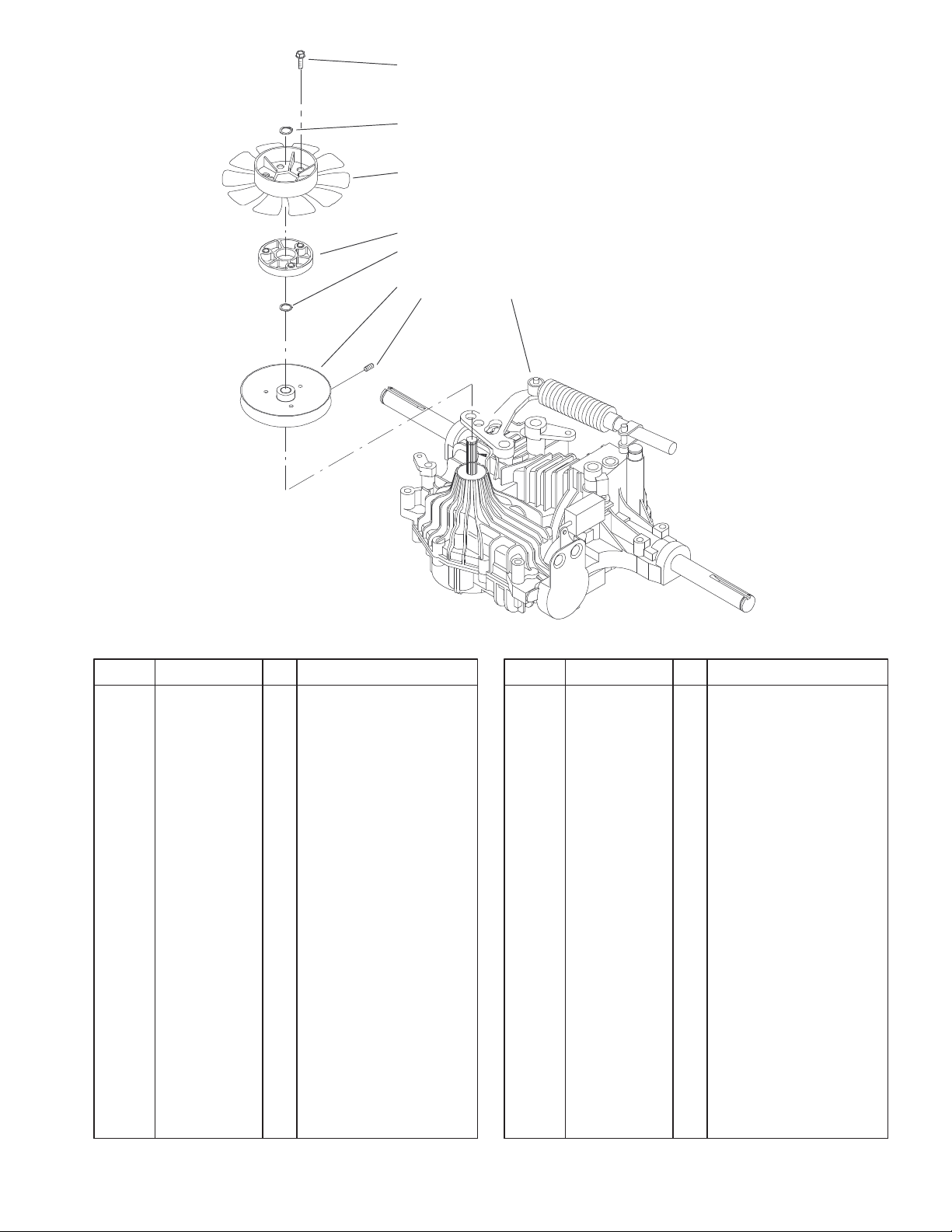
Transaxle Fan and Pulley Assembly
DescriptionPart No. Qty.Ref. No. DescriptionPart No. Qty.Ref. No.
1 49–2040 3 Screw–Tapping
2 32151–84 1 Ring–Shaft, Ext
3 92–6742 1 Fan – Hydro
4 92–6943 1 Spacer – Fan
5 920242 1 Washer
6 92–6686 1 Pulley–Hydro Trans
7 3245–32 1 Screw–HS
8 104–5099 1 Transaxle–Tufftorq
8
Sheet No.:0
3
3325–913
20
19
7
15
3
11
18
21
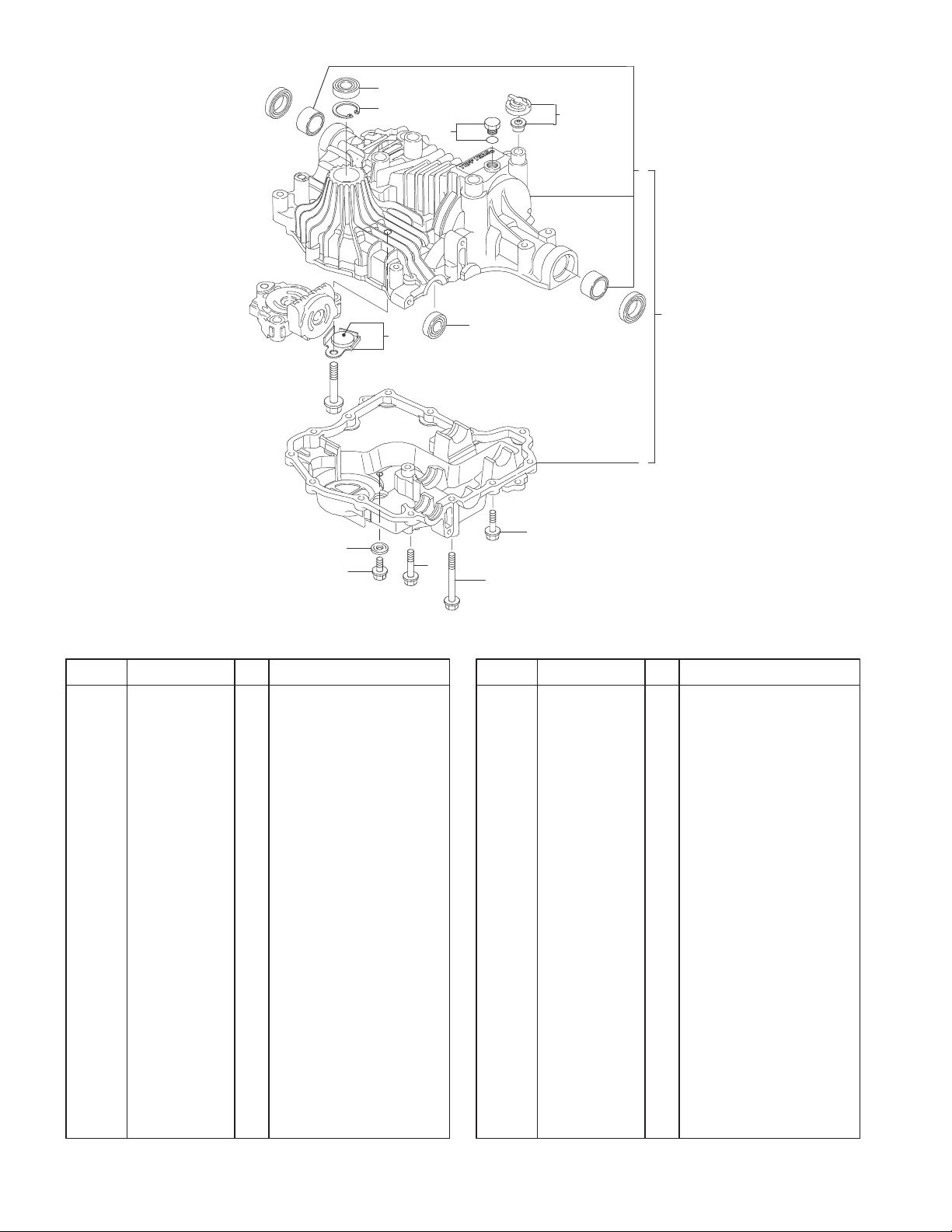
Transaxle Case Assembly
DescriptionPart No. Qty.Ref. No. DescriptionPart No. Qty.Ref. No.
2 105–1351 1 Transaxle Case ASM
3 105–1352 1 Case–Upper
6 105–1353 1 Case–Lower
7 104–3256 1 Valve–Vent, 15
10 93–0354 1 Bolt
11 93–0355 1 Magnet
14 105–1355 1 Seal
15 93–0356 1 Plug–Packing
18 93–0359 1 Washer–Seal
19 93–0360 1 Ring
20 93–0361 1 Seal
21 93–0362 1 Bolt
22 93–0363 11 Screw – Tapping
23 93–0364 2 Screw–TAP
23
14
2
6
22
10
Sheet No.:2
4
28
17
20
3325–913
19
16
7
6
5
SMALL HOLE
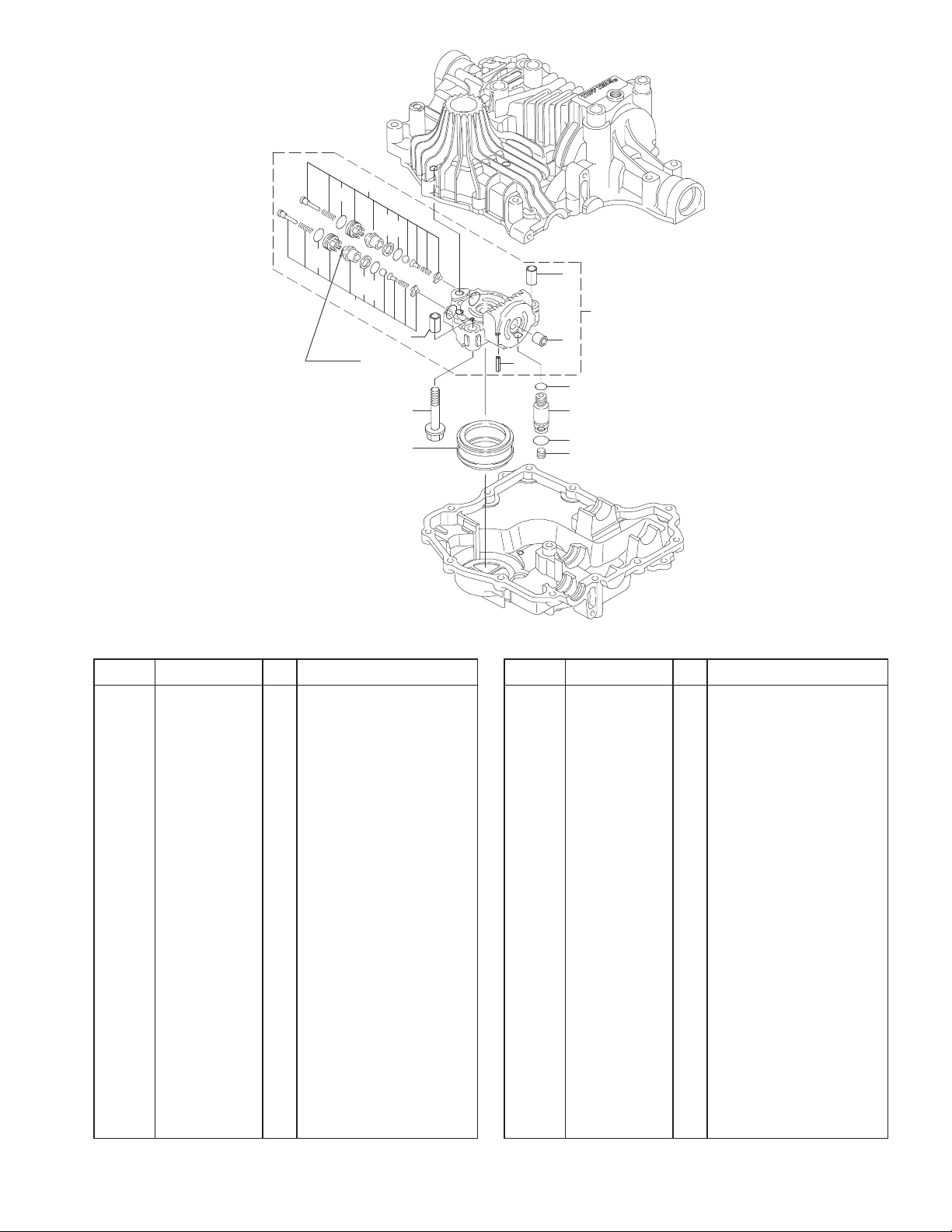
Center Case Assembly
DescriptionPart No. Qty.Ref. No. DescriptionPart No. Qty.Ref. No.
1 93–0476 1 Connector
2 105–1356 1 Case–Center
3 93–0471 2 Pin–Knock
5 105–1357 1 Valve
6 93–0465 1 Packing
7 93–0466 1 Ring–Back Up
16 105–1358 1 Packing
17 105–1359 1 Valve
19 93–0465 1 Packing
20 93–0466 1 Ring–Back Up
28 105–1358 1 Packing
29 105–1360 2 Pin
30 93–0472 1 Bushing
31 105–1361 1 Filter
32 93–0474 1 Plug
33 93–0481 1 Packing
34 104–3298 1 Packing
35 93–0479 3 Bolt
35
31
3
2
3
29
30
33
1
34
32
Sheet No.:3
5
3325–913
8
7
10
7
8
9
1
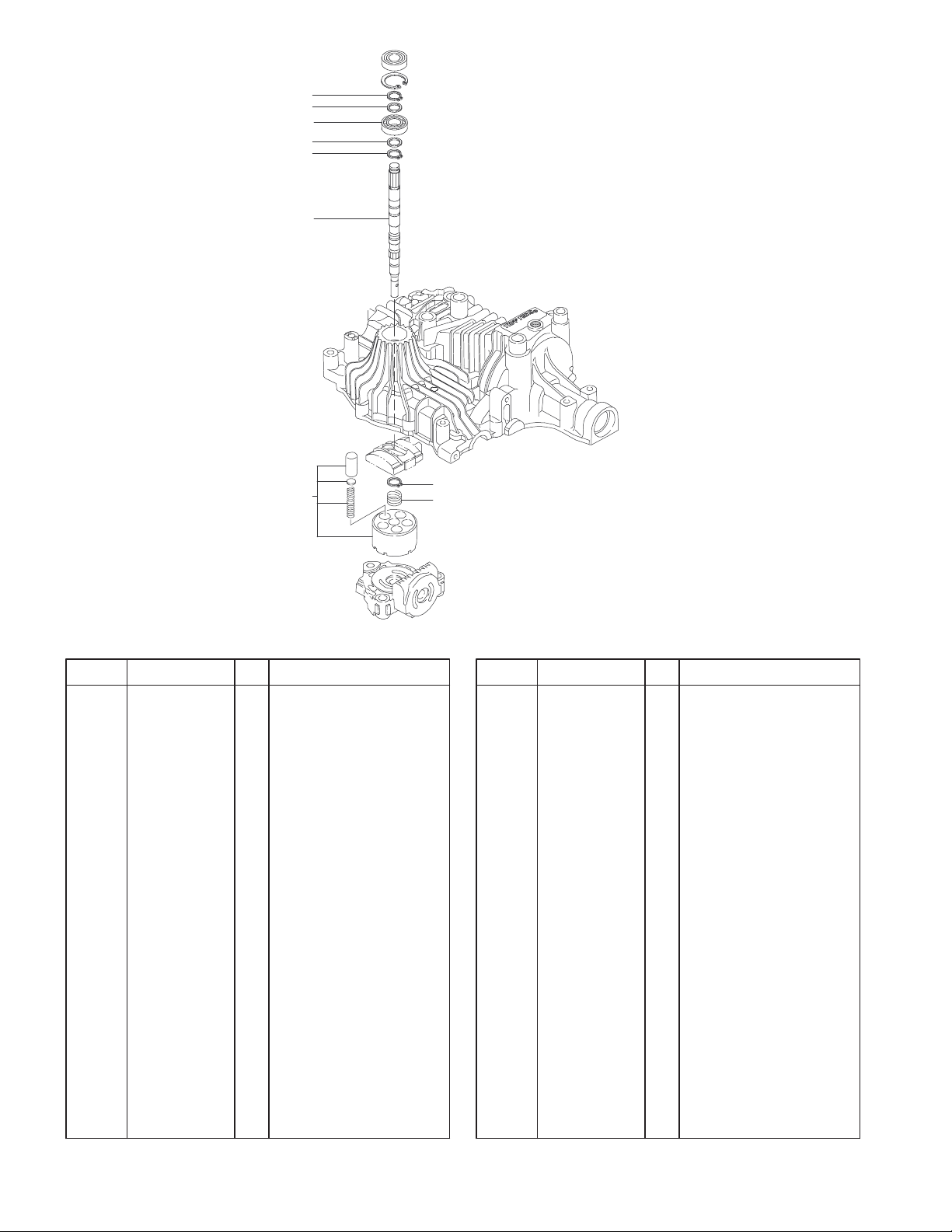
Cylinder Block Assembly
DescriptionPart No. Qty.Ref. No. DescriptionPart No. Qty.Ref. No.
1 104–3281 1 Block–Cylinder, Cmp
6 93–0370 1 Spring
7 93–0371 2 Washer
8 93–0373 3 Ring–Snap
9 105–1362 1 Shaft–Pump
10 93–0374 1 Bearing–Ball
8
6
Sheet No.:4
6
 Loading...