

Page 1
FORM NO. 3326–335
Parking Brake Kit
Proline Mid–Size Hydro Mowers
Part No. 105–0898
Safety
To comply with ANSI B71.4 1999 Standard, this
parking brake kit must be added to this machine.
Note: The addition of attachments made by
other manufacturers that do not meet
American National Standards Institute
certification will cause noncompliance
of this machine.
Loose Parts
Note: Use the chart below to identify parts for assembly.
INSTALLATION
INSTRUCTIONS
Safe Operation
• Be sure all drives are in neutral and parking brake is
engaged before starting engine.
• Stop on level ground, disengage drives, engage
parking brake, shut off engine before leaving the
operator ’s position for any reason including emptying
the catchers or unclogging the chute.
• Check brake operation frequently. Adjust and service
as required.
DESCRIPTION QTY. USE
Grip
Handle
Upper bracket
Bushing
Bolt, 3/8 x 2.50 in.
Washer, 7/16 in.
Lock Nut, 3/8 in.
Bracket Assembly
Bolt, 5/16 x 3–1/4 in., T–bar machines only
Lock Nut, 5/16 in.
Bolt, 1/4 x 7/8 in.
Lock Nut, 1/4 in.
Bolt, 5/16 x 7/8 in., Pistol grip machines only
1
1
1
1
1
2
1
1
1
1
1
1
1
Assemble handle and bracket
Installing Upper Bracket
The Toro Company – 2001
Printed in USA
All Rights Reserved
Page 2
Installation Instructions
DESCRIPTION USEQTY.
Brake Assembly
Bolt, 3/8 x 1–1/4 in.
Lock Nut, 3/8 in.
Bolt, 3/8 x 1–3/4 in.
Jam Nut, 3/8 in.
Flange Nut, 5/16 in.
Bolt, 5/16 x 1–1/4 in.
Spring
Flange Nut, 3/8 in.
Brake Rod
Clevis Pin
Hair pin cotter
Yoke
Cotter Pin
Kit Installation
1
3
3
1
1
2
1
1
1
1
1
1
1
1
Installing Brake Assembly
Installing Brake Rod
3
4
1
2
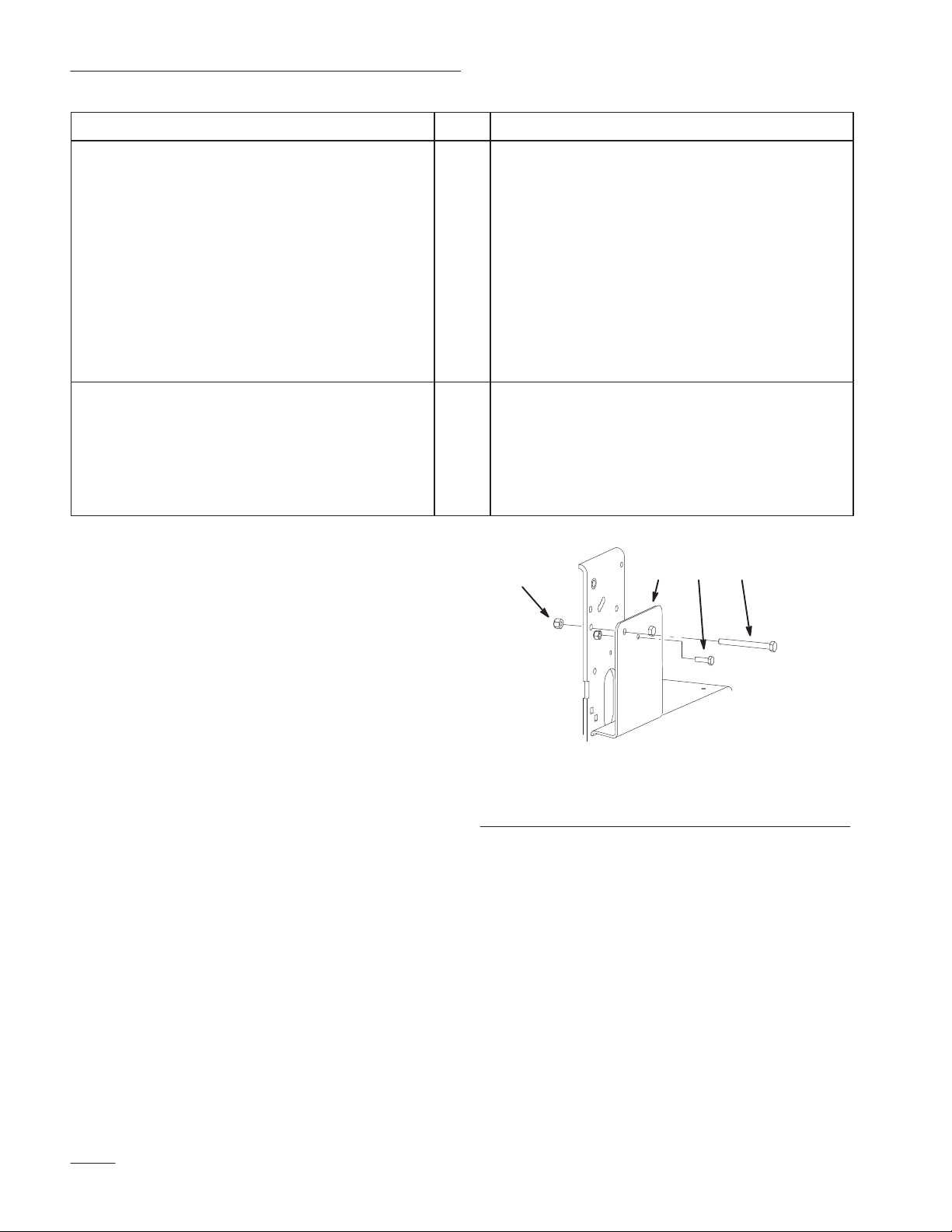
Remove Bolts
1. Remove long bolt from the rightside bracket as
shown in figure 1. Discard this bolt and nut.
2. Remove the one short bolt that holds the bearing
to the bracket as shown in figure 1. Discard this
bolt and nut.
Note: Save the spacer used on T–bar
machines.
m–5452
Figure 1
1. Long bolt
2. Short bolt
3. Nut
4. Rightside bracket
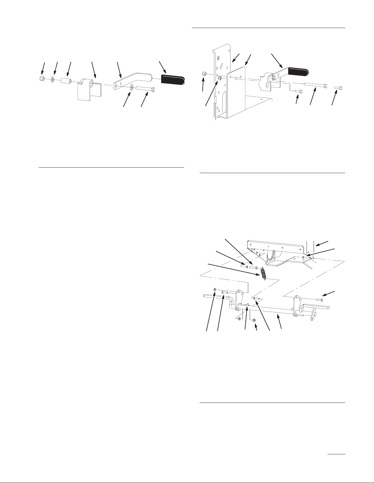
Assemble Handle and Bracket
1. Install grip onto handle (Fig. 2).
2. Install bushing into the upper bracket (Fig. 2).
3. Install the handle to bracket with a bolt
(3/8 x 2.50 in.), 2 washers (7/16 in.) and a
locknut (3/8 in.) (Fig. 2).
2
Page 3
Installation Instructions
1
65
1
6245
7
3
4 3
m–5448
Figure 2
1. Upper bracket
2. Bushing
3. Bolt, 3/8 x 2–1/2 in.
4. Washer, 7/16 in.
5. Locknut. 3/8 in.
6. Handle
7. Grip
Install Upper Bracket
IMPORTANT: Use the correct bolt in step 1
according to the style of machine you have.
Use a 5/16 x 7/8 in. bolt for a pistol grip
machine.
Use a 5/16 x 3–1/4 in. bolt for a T–bar
machine.
1. Install upper bracket to the machine frame with a
bolt (5/16 x 3–1/4 in. or 5/16 x 7/8 in.) and
locknut (Fig. 3). Install spacer on T–bar units.
2. Install upper bracket to the side plate and bearing
with a bolt (5/16 x 7/8 in.) and locknut (Fig. 3).
7
24
8
m–5450
Figure 3
1. Bracket assembly
2. Bolt, 5/16 x 3–1/4 in., for
T–bar
3. Locknut. 5/16 in.
4. Bolt, 1/4 x 7/8 in.
5. Machine frame
6. Side plate
7. Locknut. 1/4 in.
8. Bolt, 5/16 x 7/8 in., for
Pistol grip
Install Brake Assembly
1. Install brake assembly to machine frame with 3
bolts (3/8 x 1–1/4 in.) and 3 locknuts (3/8 in.)
(Fig. 4).
4
5
7
9
3
2
28
11
m–5447
10 1
6
Figure 4
1. Brake assembly
2. Bolt, 3/8 x 1–1/4 in.
3. Lock Nut, 3/8 in.
4. Upper bolt, 3/8 x 1–3/4 in.
5. Jam Nut, 3/8 in.
6. Flange Nut, 5/16 in.
7. Spring
8. Flange Nut, 3/8 in.
9. Machine frame
10. Lower bolt, 5/16 x
1–1/4 in.
11. Tab
2. Install lower bolt (5/16 x 1–1/4 in.) in the brake
assembly using two flange nuts (5/16 in.) on
both sides of the tab (Fig. 4 and 5).
3
Page 4

Installation Instructions
Note: Install bolt so 2 or 3 threads show out
of the flange nut (Fig. 4 and 5).
3. Install spring onto upper bolt (3/8 x 1–3/4 in.) as
shown in figures 4 and 5.
4. Install upper bolt (3/8 x 1–3/4 in.) in the brake
assembly and machine frame using a flange nut
(5/16 in.) and jam nut (5/16 in.) on both sides of
the tab (Fig. 4 and 5).
Note: Install bolt so 2 or 3 threads show out
of the flange nut (Fig. 4 and 5).
5. Install spring onto lower bolt (5/16 x 1–1/4 in.)
as shown in figures 4 and 5.
9
8
5
6
9
2
7
3
4
10
Topview
1
2. Install yoke onto the brake assembly with a
clevis pin and a hairpin cotter.
3. Install the “L” shaped end into brake handle.
with a cotter pin.
6
5 2
2
4
7
3
5
1. Yoke
2. Brake rod
3. Clevis pin
4. Brake assembly
Figure 6
5. Hairpin cotter
6. Handle
7. 1–1/4 in.
1
m–5451
m–5455
Figure 5
1. Brake assembly
2. Upper bolt, 3/8 x 1–3/4 in.
3. Jam Nut, 3/8 in.
4. Flange Nut, 5/16 in.
5. Spring
6. Flange Nut, 3/8 in.
7. Machine frame
8. Lower bolt, 5/16 x
1–1/4 in.
9. Two or three threads
showing
10. Tab
Install Brake Rod
1. Install yoke onto brake rod, 1–1/4 in. from the
top of threads.
Check Operation of Brake
1. Check brake for proper operation as described
below.
2. Refer to Brake Service if adjustment is needed
on page 5.
Parking Brake Operation
Always set the parking brake when you stop the machine
or leave it unattended. Before each use, check brake for
proper operation.
If the parking brake does not hold securely, an adjustment
is required. Refer to Brake Service on page 5.
4
Page 5

Caution
Children or bystanders may be injured if they
move or attempt to operate the machine while it is
unattended.
Always remove the ignition key and set the
parking brake when leaving the machine
unattended, even if just for a few minutes.
Installation Instructions
3. To set the parking brake, it should take a reasonable
amount of force. If it engages too hard or easily,
adjustment is required. Refer to Adjusting the Brake
on page 5.
Note: When the brake is engaged, the brake handle
should be close to the 11 o’clock position.
4. If there is a reasonable amount of force, no adjustment
is required.
Adjusting the Brake
Setting the Parking Brake
1. Pull the brake handle rearward (Fig. 7).
Releasing the Parking Brake
1. Push the brake handle forward (Fig. 7).
Figure 7
1. Parking brake lever
(released position)
The brake handle is on the right side of machine (Fig. 8).
If the parking brake does not hold securely, an adjustment
is required.
1. Check the brake before you adjust it; refer to Checking
the Brake, page 5.
2. Release the parking brake; refer to Releasing the
Parking Brake, page 5.
1
3. To adjust the brake, remove the hair pin cotter and
clevis pin from the lower brake lever (Fig. 8).
4. Rotate the yoke in to tighten the brake and rotate out
to loosen the brake (Fig. 8).
5. Secure yoke to lower brake lever with the hair pin
cotter and clevis pin (Fig. 8).
6. Check the brake operation again; refer to Checking the
Brake, page 5.
m–5383
2
Brake Service
Service Interval/Specification
Before each use, check brake for proper operation.
Always set the parking brake when you stop the machine
or leave it unattended. If the parking brake does not hold
securely, an adjustment is required.
Checking the Brake
1. Set the parking brake (Fig. 8).
2. Park the machine on a level surface, disengage the
power take off (PTO) and turn the ignition key to
“OFF” to stop the engine. Remove the key.
1
3
14
1. Yoke
2. Parking brake lever
(released position)
m–5384
Figure 8
3. Clevis pin
4. Hairpin cotter
5
Page 6

Installation Instructions
6
Page 7

Installation Instructions
7
Page 8

Installation Instructions
8
 Loading...