

Page 1
Thigh Support Kit
Dingo Compact Utility Loader
Part No. 105-0330
Loose Parts List
Description Qty. Use
Form No. 3327-521
Installation Instructions
Thigh support pad
Adjustment plate
Thigh support bracket
Carriage bolt, 5/16 x 7/8 inch
Flat washer
Locknut, 5/16 inch
Bolt, 5/16 x 7/8 inch
Knob
CE Decal (104–6109) 1 Install on international units.
1
1
1
4
Install the Thigh Support Kit
4
6
2
2
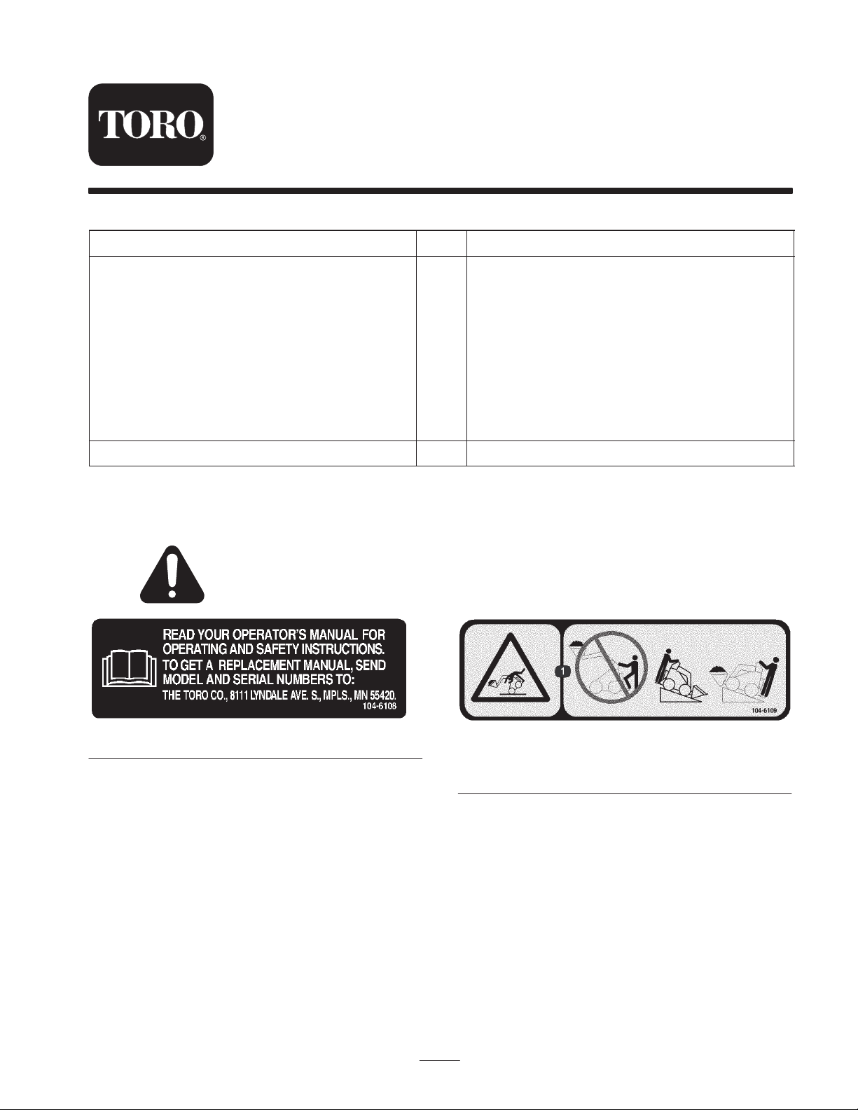
Safety and Instruction Decals
Safety decals and instructions are easily visible to the operator and are located near any area
of potential danger. Replace any decal that is damaged or lost.
104-6108
2002 by The Toro Company
8111 Lyndale Avenue South
Bloomington, MN 55420-1196
104-6109
1. Tipping hazard—do not step off the platform with the load
raised and move the traction unit with the heavy end up hill.
All Rights Reserved
Printed in the USA
1
Page 2
Installing the Kit
1. Check the front of your control panel for two holes
located between the manual tube mounting brackets
(Fig. 1).
1
m–6346
Figure 1
1. Mounting holes
If these holes do not exist, complete the following:
A. Use the thigh support bracket as a template to mark
the locations for 2 holes centered between the
manual tube mounting brackets and 1/2 inch above
the bottom of the control panel.
3
2
8
m–6345
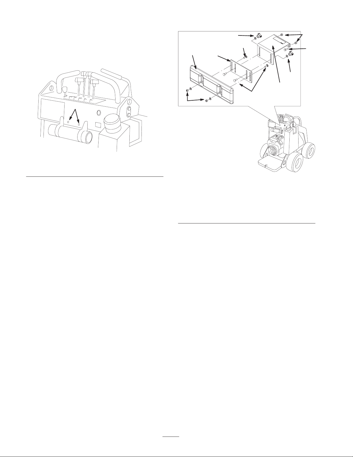
1. Thigh support bracket
2. Adjustment plate
3. Thigh support pad
4. Locknut, 5/16 inch
5. Bolt, 5/16 x 7/8 inch
6
7
Figure 2
4
5
6
1
7
6. Knob and flat washer
7. Carriage bolt,
5/16 x 7/8 inch
8. Locknut, 5/16 inch and
flat washer
B. Drill 2 holes (11/32 inch dia) at the marked
locations.
2. Install the thigh support bracket on the control panel
(Fig. 2), using 2 bolts (5/16 x 7/8 inch) and 2 locknuts
(7/8 inch).
3. Install the adjustment plate on the thigh support bracket
(Fig. 2), using 2 carriage bolts (5/16 x 7/8 inch), 2 flat
washers, and 2 knobs.
4. Install the thigh support pad on the adjustment bracket
(Fig. 2), using 2 carriage bolts (5/16 x 7/8 inch), 2 flat
washers, and 2 locknuts (5/16 inch).
Installing the CE Decal
(International Units Only)
If you are installing this kit on a machine used outside of
the United States, install decal number 104–6109 over
decal number 104–6108, located on the thigh support
mounting bracket.
Adjusting the Thigh Support
To adjust the thigh support, loosen the knobs and raise or
lower the support pad to the desired height. You can also
obtain additional adjustment by loosening the nuts securing
the pad to the adjustment plate, moving the plate up or
down as needed. Tighten all fasteners securely when
finished.
2
 Loading...