

Page 1

Form No. 3328-187
High-Output Alternator Kit
Twister Utility Vehicle
Part No. 104–6978
Installation Instructions
Note: You will need the Clutch Removal T ool (part number TOR4094) (Fig. ) and a torque wrench to perform this procedure.
You can obtain the Clutch Removal tool from you Authorized Toro Dealer.
Loose Parts
Description Qty. Use
Alternator mounting bracket
Alternator
Bolt, 3/8 x 2-1/2 inches
Bolt, 3/8 x 2 inches
Bolt, 3/8 x 1-3/4 inches
Flange nut, 3/8 inch
Bolt, M8 x 45 mm
Lock washer, 5/16 inch
Flat washer, 11/32 inch
Small spacer
Alternator drive pulley
Spacer
Belt
Bolt, 1/4 x 1 inch
Lock washer, 1/4 inch
Wire harness 1 Connect the wire harness
1
1
1
2
1
4
1
1
1
1
1
1
1
4
4
Install the alternator.
Install the alternator.
2002 by The Toro Company
8111 Lyndale Avenue South
Bloomington, MN 55420-1196
All Rights Reserved
Printed in the USA
1
Page 2
Removing the Drive Clutch
1. Park the machine on a level surface, stop the engine, set
the parking brake, and remove the key from the ignition
switch.
2. Remove the drive belt from the driven clutch on the
transaxle and the drive clutch on the engine.
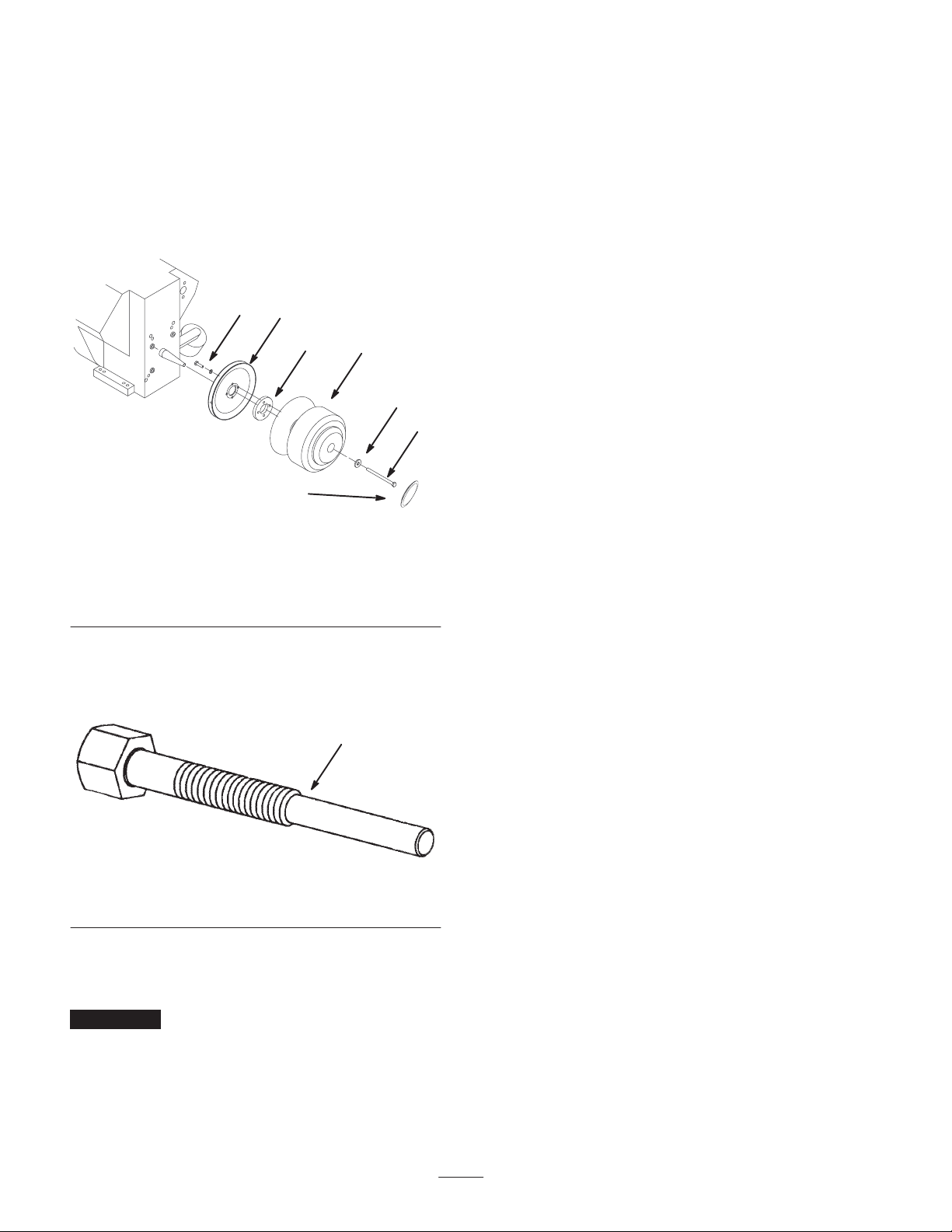
3. Remove the plastic cap from the drive clutch (Fig. 1).
7
6
5
1
4
3
2
Figure 1
1. Drive clutch
2. Plastic cap
3. Bolt
4. Washer
5. Spacer
6. Alternator drive pulley
7. Bolt, 1/4 x 1 inch, and
lock washer, 1/4 inch
4. Remove the bolt and washer securing the drive clutch to
the engine tapered shaft (Fig. 1).
5. Grease the end of the clutch removal tool (Fig. 2).
1
Figure 2
1. Clutch removal tool
6. Insert the tool into the end of the clutch and thread it in
slowly using a wrench until the clutch comes off of the
tapered drive shaft.
Important T o prevent damage to the clutch threads,
thread the tool into the clutch only enough to remove it.
2
Page 3

Installing the Alternator
12
11
6
7
6
6
1. Engine mounting pan
2. Alternator mounting bracket
3. Bolt, 3/8 x 2-1/2 inches
4. Drill holes, 7/16 inch dia
5. Bolt, 3/8 x 2 inches
6. Flange nut, 3/8 inch
2
1. Bolt the alternator bracket to the left side of the engine
mounting pan (Fig. 3), using a bolt (3/8 x 2-1/2 inches)
and a flange nut (3/8 inch). Ensure that the bracket
lines up with the side of the frame.
2. Using the bracket as a template, mark 2 hole locations
on the flange of the engine mounting pan (Fig. 3).
3. Remove the alternator bracket and fasteners and drill 2
holes (7/16 inch dia) through the engine mounting pan
at the marked locations (Fig. 3).
4. Install the bracket on the pan (Fig. 3) using 2 bolts
(3/8 x 2 inches) and 2 flange nuts (3/8 inch) and the
fasteners you removed in step 3.
5. Secure the thick flange on the alternator to the bottom
hole on the bracket (Fig. 3) using a bolt
(3/8 x 1-3/4 inches) and a flange nut (3/8 inch).
10
9
4
8
Figure 3
7. Alternator
8. Bolt, 3/8 x 1-3/4 inches
9. Bolt, M8 x 45 mm
4. Slide the drive clutch and pulley onto the engine drive
shaft and secure it with the washer and bolt you
removed previously.
5. Torque the bolt to 25 to 30 ft-lb (40 N⋅m).
6. Place the plastic cap over the end of the drive clutch.
7. Loop the alternator drive belt over the alternator pulley.
8. Push the top of the alternator away from the drive
pulley and tighten the bolt (M8 x 45 mm) in the
adjustment slot when the top span of the belt flexes 1/4
inch when you apply 10 lb (4.5 kg) to the center of the
span (Fig. 4).
5
3
1
m-6377
10. Lock washer, 5/16 inch
11. Washer, 11/32 inch
12. Spacer
1/4”
10 lb
6. Secure the thin flange with the threaded hole to the
adjustment slot in the bracket (Fig. 3) using a bolt
(M8 x 45 mm), a lock washer (5/16 inch), a
washer (11/32 inch), and a spacer. Do not fully tighten
the fasteners.
Installing the Alternator Drive
Pulley and Belt
1. Install the alternator drive pulley and spacer to the back
of the drive clutch, as illustrated in Figure 1, using
4 bolts (1/4 x 1 inch) and lock washers (1/4 inch).
2. Torque the bolts to 41 to 55 in-lb (5 to 6 N ⋅m).
3. Loop the alternator drive belt around the pulley.
Figure 4
9. Tighten all fasteners.
3
Page 4

Connecting the Wire Harness
1. Disconnect the in-engine alternator from the battery by
disconnecting the red connector from the white
connector at the front of the engine (Fig. 5).
1
2
5. Connect the blue connecter to a 25 amp fuse position on
the fuse block (install a 25 amp fuse in the position if
there is no fuse) (Fig. 7).
3
2
1
m–6408
Figure 5
1. Red connector 2. White connector
2. Connect the white connector on the wire harness to the
port on the back of the alternator (Fig. 6).
3
m–6406
1
Figure 6
1. White connector
2. Eye-ring terminal on the
red wire
3. Alternator
m–6407
Figure 7
1. Blue connector to a 25
amp fuse position
2. Eye-ring terminal on the
red wire.
3. Starter solenoid
6. Connect the eye-ring terminal on the red wire to the
positive terminal (terminal with the wire running
directly to the battery) on the starter solenoid near the
battery (Fig. 7).
Testing the Alternator
2
1. Set the parking brake and start the engine.
2. Using a voltmeter, check the system voltage across the
positive and negative battery terminals.
If the new alternator is functioning correctly, the
voltage should read between 13 and 15 volts at high
idle.
3. Connect the eye-ring terminal on the red wire to the
stud on the alternator (Fig. 6).
4. Route the other end of the wire harness over the
alternator and along the vehicle frame to the fuse box
area.
4
 Loading...