

Page 1

Form No. 3351-930
Brake and Tail Light Kit
Workman) 1100/2100 and Twistert Utility Vehicles
Part No. 104–6697
Installation Instructions
Important Before installing this kit, you must have Wiring kit number 99–7924 installed on the unit. This kit upgrades
the wiring on the vehicle so that it will accept the several optional kits that require connections to the electrical system.
Note: If you will be installing the horn kit or the signal light kit, obtain them before installing this kit. It is much easier to
install the three kits together, than to install them separately.
Loose Parts
Description Qty. Use
Screw, 1/2 x 1/2 inch
Lock washer, 1/2 inch
Cotter pin
1
Brake switch
Brake switch bracket
Bolt, #6
Locknut, #6
1
1
1
1
1
1
1
1
Install the brake switch
2
2
Dash harness
Flasher
Relay
Timer
Bolt, 1/4 x 1-3/8 inch
Bolt, 1/4 x 3/4 inch
Locknut, 1/4 inch
R-clamp, large
R-clamp, small
Wire tie
1
Not used to install brake switch on models with serial numbers 230000001 or higher.
1
1
1
1
1
2
3
1
1
2
Install the dash harness
W 2004 by The Toro Company
8111 Lyndale Avenue South
Bloomington, MN 55420-1196
All Rights Reserved
1
Printed in the USA
Page 2

Description Qty. Use
Tail light
Silicone sealant (not supplied, purchase before
installing)
Rear harness
R-clamp, small
Screw, 1/4 x 0.82 inch
Adapter harness
Wire tie
Fuse
Front reflector
Bolt, #10
Locknut, #10
Rear reflector
Screw, #10
1
0
1
3
3
1
2
1
2
2
2
2
4
Install the tail lights and rear harness
Install the reflectors
2
Page 3
Preparing the Vehicle
1. Position the machine on a level surface, stop the
engine, and remove the key.
Caution
If you leave the key in the ignition switch,
someone could accidently start the engine and
seriously injure you or other bystanders.
Remove the key from the ignition switch before
you do any maintenance.
2. Remove the hood from the vehicle by removing the 2
screws on top of the hood, the 2 bolts on each fender,
and the 4 bolts from the bottom of the hood.
Installing the Brake Switch
(Workman 2110, Twister1600, or any
model with Serial Number of 230000001
or Higher)
1. Install brake switch to pedal assembly using #6 bolts
and lock nuts (Fig. 2).
5
(Workman 2100, 1100, or Twister 1400
with Serial Numbers 229999999 or Lower)
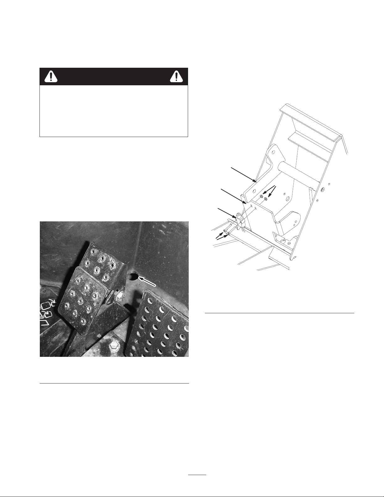
3. Drill a hole (7/8 in. dia.) in the floor of the vehicle in
front of the brake pedal in the location shown in
Figure 1.
1
Figure 1
1. Hole, 7/8 in.
4
1
3
1. Brake switch
2. Bolts, #6
3. Lock nuts, #6
2. Make sure brake pedal arm is aligned and makes
contact with brake switch button when pedal is
released.
3. Check the depth of brake switch button while of brake
switch is engaged. Switch should be adjusted to allow
the button to be depressed but not bottomed out when
brake pedal is released and button should be extended
with clearance when brake is applied.
2
m–6599
Figure 2
4. Pedal assembly
5. Brake pedal arm
Note: If you are installing the horn kit, install the horn at
this time, but do not connect any of the wires to the horn
yet.
4. Verify the alignment and actuation of switch by
applying and releasing brake.
3
Page 4
(Workman 2100, 1100 or Twister 1400 with
Serial Numbers 229999999 or Lower)
1. If you have a floor mat, remove it from around the
accelerator and brake pedals.
2. Remove the metal plate on the floor surrounding the
pedals.
3. Disconnect the brake rod from the brake pedal.
4. Remove the bolt securing the brake pedal pivot rod
(Fig. 3).
1
9. Insert the brake pedal assembly into the pedal box and
secure it into the rear position using the pivot rod
removed previously.
10. Secure the pivot rod with the bolt removed previously.
11. Connect the brake rod to the brake pedal using a new
cotter pin.
12. Loosely mount the brake switch onto the brake switch
bracket (Fig. 5) using 2 bolts (#6) and 2 locknuts (#6).
2
m-5780
Figure 3
1. Pivot rod 2. Bolt
5. Pull out the pivot rod, removing the brake pedal
(Fig. 3).
6. Drill a hole (27/64 in. dia.) through the brake pedal in
the location illustrated in Figure 4.
3
4
1
2
4
1
3
4
Figure 5
1. Pedal box
2. Brake switch
3. Brake switch bracket
4. Existing bolts
13. Bolt the bracket to the back of the pedal box using the
two bolts on the back of the box (Fig. 5). Secure the
bracket so that the button on the switch comes to the
center of the screw head you installed on the brake
pedal.
14. Adjust the switch so that the button is pressed in by the
pedal when the pedal is at rest. The pedal should not
touch the body of the switch. Tighten the bolts and
nuts securing the switch once you have it in the correct
position.
2
m-5844
Figure 4
1. 3/4 in.
2. 5/16 in.
3. Screw, 1/2 x 1/2 in.
4. Lock washer, 1/2 in.
7. Tap the hole with a 1/2–13 in. tap.
8. From the right side of the pedal, install a screw (1/2 x
1/2 in.) and lock washer (1/2 in.) into the hole (Fig. 4).
4
Page 5

Installing the Dash Harness and Components
Figure 6 illustrates the dash wiring harness. Refer to it throughout this procedure.
3
12
1
5
6
4
2
7
1. To flasher
2. To relay
3. To timer
4. To ground stud
5. To white wire on the fuse
block
6. To horn button (if installed)
Installing the Flasher, Relay, and Timer
1. Connect the flasher to the dash harness (Fig. 6 and 7).
1
Figure 6
7. To light switch
8. To ignition switch
9. To horn (if installed)
11
10
9
8
m-5816
10. Not used
11. To main wire harness
12. To brake switch
1
m–5818
Figure 7
1. Flasher
2. Connect the relay to the dash harness (Fig. 6 and 8).
m–5817
Figure 8
1. Relay
3. Connect the timer to the dash harness as illustrated in
Figure 6 and 9.
5
Page 6

3
4
2
5
1
m–5819
Figure 9
1. White wire to terminal 1
2. Black wire to terminal 2
3. White wire pigtail to
terminal C
4. Green wire to N.O.
terminal
5. Timer
4. Connect the timer to the front side (under the hood) of
the dash plate using a bolt (1/4 x 1-3/8 in.) and locknut
(1/4 in.) in the location illustrated in Figures 10 and
11.
2
1
3
1
2
Figure 11
Viewed from the Front of the Vehicle
1. Timer 2. Flasher
5. Connect the flasher to the back side (under the dash)
of the dash plate using a large R-clamp, a bolt (1/4 x
3/4 in.), and a locknut (1/4 in.) in the location
illustrated in Figures 10 and 12.
2
Figure 10
Viewed from the Front of the Vehicle
1. Hole for the timer (cut and remove the cable tie if necessary)
2. Hole for the flasher 3. Hole for the relay
1
Figure 12
Viewed from the Under the Dash
1. Flasher 2. Relay
6. Connect the relay to the back side (under the dash) of
the dash plate using a bolt (1/4 x 3/4 in.) and locknut
(1/4 in.) in the location illustrated in Figures 10 and
12.
Note: If you had previously installed the Horn Kit,
disconnect the wires from the horn button. Connect the
two eye connectors on the dash harness to the horn button
6
Page 7

(Fig. 6). If you are installing the horn kit, refer to the
Horn Kit Installation Instructions for information on
instaling the horn button.
Connecting the Dash Harness to the
Fuse Block and the Light Switch
1. Attach the ground lug on the harness to the ground
stud on the dash plate (Fig. 6 and 13).
2
1
Figure 13
Viewed from the Under the Dash
1. Ground stud 2. Fuse block
4. Insert the connector on the pink double wire from the
dash harness into the number 5 slot on the light switch
harness as shown in Figure 6 and 14.
5. Insert the connector on the purple wire from the dash
harness into the number 6 slot on the light switch
harness as shown in Figure 6 and 14.
6. Plug the light switch harness into the back of the light
switch.
Connecting the Dash Harness to the
Ignition Switch (Models with Serial
Numbers 220000001 or Lower)
1. Look at the back of the ignition switch.
2. Connect the harness to the ignition switch as follows:
• If you have 5 connection pins on the back of the
ignition switch, remove the red or yellow wire and
plug the violet wire (Fig. 6) on the harness into its
spot.
• If you have 4 connection pins on the back of the
ignition switch, remove the violet wire and plug
the violet wire (Fig. 6) on the harness into its spot.
3. Plug the wire you removed from the ignition switch
into the wire coming out of the connector on the violet
wire that you plugged into the ignition switch.
2. Plug the power lead on the harness into the white
connector on the fuse block (Fig. 6 and 13).
Note: If the Horn Kit was previously installed, remove all
wires from the horn.
3. Unplug the light switch harness from the back of the
light switch (Fig. 14).
1
2
1. Light switch harness
2. Double pink wire
3
Figure 14
3. Purple wire
m–5820
Connecting the Dash Harness to the
Ignition Switch (Models with a Serial
Numbers of 220000001 or Higher)
1. Look at the back of the ignition switch.
2. Connect the harness to the ignition switch as follows:
• If you have 5 connection pins on the back of the
ignition switch, connect the violet wire (Fig. 6) on
the harness to the violet pigtail wire on the back of
the switch.
• If you have 4 connection pins on the back of the
ignition switch, connect the violet wire (Fig. 6) on
the harness to the violet wire on the back of the
switch.
Connecting the Dash Harness to the Main
Harness and the Brake Switch (Models
with Serial Numbers 229999999 or Lower)
Note: If you are also installing or have already installed
the Horn Kit, connect the horn leads of the dash harness to
the horn (Fig. 6).
1. Locate the plug on the main wire harness of the
vehicle that is not currently connected to anything.
7
Page 8

2. Connect the female connector on the dash harness
(Fig. 6) to the empty male connector on the main
harness.
Note: The male connector next to the female connector on
the dash harness will not be used to install this kit. It is
used to connect other kits to the vehicle.
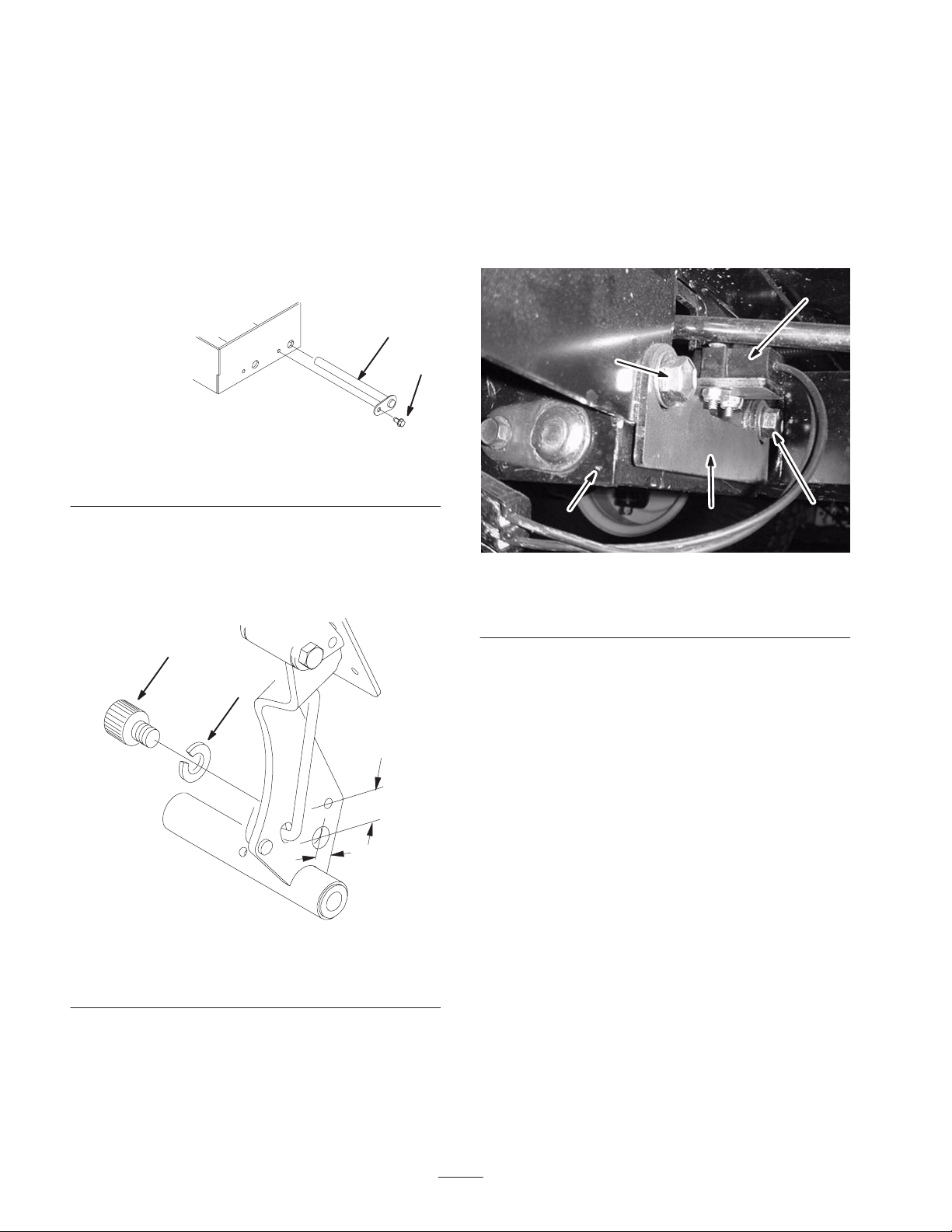
3. Route the long end of the dash harness with the
terminal connector (Fig. 6) along the vehicle support
and through the hole you drilled in the floor of the
vehicle.
4. Slide an R-clamp over the harness near the end
(Fig. 15).
5. Connect the terminal connector on the dash harness to
the connector on the brake switch harness under the
vehicle (Fig. 15).
Connecting the Dash Harness to the Main
Harness and the Brake Switch (Models
with Serial Numbers 230000001 or
Higher)
Note: If you are also installing or have already installed
the Horn Kit, connect the horn leads of the dash harness to
the horn (Fig. 6).
1. Locate the plug on the main wire harness of the
vehicle that is not currently connected to anything.
2. Connect the female connector on the dash harness
(Fig. 6) to the empty male connector on the main
harness.
Note: The male connector next to the female connector on
the dash harness will not be used to install this kit. It is
used to connect other kits to the vehicle.
1
2
3
4
Figure 15
1. Pedal box
2. Terminal connector
6. Use a wire tie to secure the brake switch harness to the
brake switch bracket.
7. Attach the R-clamp to side of the pedal box with the
bolt that secures the accelerator pedal pivot rod to the
brake box (Fig. 15).
8. Remove all slack from harness under the vehicle.
9. Seat the grommet on the harness in the hole you
drilled in the floor.
3. Brake switch harness
connector
4. R-clamp
3. Route the long end of the dash harness with the
terminal connector (Fig. 6) to the brake switch.
4. Connect the terminal connector on the dash harness to
the connector on the brake switch.
5. Use a wire tie to secure the brake switch harness to the
brake switch bracket.
6. Bundle excess wiring and use 2 wire ties to secure the
cable to the vehicle support.
7. Install the hood.
Installing the Taillights
1. Drill 2 holes (1/4 in. dia.) in each taillight location in
the back of the bed. The location of these holes is
molded into the box.
2. Drill a hole (1-1/2 in. dia.) in each taillight location in
the back of the bed as shown in Figure 16.
1-3/8 in.
(3.5 cm)
10. Use 2 wire ties to secure the cable to the vehicle
support.
11. Install the hood.
m-5855
1/2 in.
(1.3 cm)
Figure 16
3. Raise the bed.
8
Page 9

4. Through the right side, inside surface of the box
toward the rear, drill a hole (1-1/2 in. dia.) through the
inner wall of the box in the location shown in
Figure 17.
1
1
Figure 19
1. Left hole
Figure 17
1. Right hole
Important Some older boxes are configured
differently on the right side. Figure 18 illustrates the hole
location on one of these boxes.
1
6. Route the harnesses on the back of the taillights
through the holes you drilled in step 1 and through the
holes you drilled in step 4 and 5.
Note: To ease installation, use a stiff wire hook to pull the
wire harnesses though the holes.
7. Apply a bead of silicone sealant around the back of
each taillight about 1/2 in. from the edge and install
each taillight onto the bed.
8. Route the rear wire harness from the left taillight
harness, across the back, and over to the right side,
securing it with 3 R-clamps and 3 screws (1/4 x
0.82 in.) (Fig. 20).
Note: You will need to drill 3 holes (13/64 in. dia.) in the
bed in which to install the R-clamps.
1
GRAPHIC #
2
Figure 18
1. Right hole
5. Through the left side, inside surface of the box toward
the rear, drill a hole (1-1/2 in. dia.) through the inner
wall of the box in the location shown in Figure 19.
Figure 20
1. Rear harness 2. R-clamps
9. Route the harness around the battery.
10. Connect the connector in the center of the rear harness
to the connector on the main wire harness located near
the battery.
9
Page 10

Note: On Workman 2100 Vehicles serial number
22000000101 and lower, use adapter harness number
104–6958 between the rear harness and the main wire
harness (Fig. 21).
1
1
2
Figure 21
1. Adapter harness 2. Main wire harness
connector
11. Route the remaining rear harness forward between the
frame and the air cleaner.
12. Connect the ring terminal on the rear harness to the
ground stud on the front right skid pan, near the base
of the engine (Fig. 22).
GRAPHIC #
Figure 23
1. Front reflector
2. Install the front reflectors, using 2 bolts (#10) and 2
locknuts (#10) (Fig. 23).
3. Drill 2 holes (13/64 in. dia.) on each side of the box in
the location shown in Figure 24, using the reflector as
a template to mark the hole locations.
1
Figure 22
1. Ground stud
13. Secure the harness to the frame with wire ties.
14. Install the fuse in the fuse block in the position
corresponding to the white wire.
Installing the Reflectors
1. Drill a hole (#10 drill bit) on each side of the hood in
the location shown in Figure 23.
1
Figure 24
1. Rear reflector
4. Install the rear reflectors, using 4 screws (#10)
(Fig. 24).
10
Page 11

Electrical Schematic
11
T–xxxx
Page 12

 Loading...