

Toro 10301, 10307, 10309, 10310, 10311 Service Manual
...
WALK BEHIND POWER
MOWER DRIVE SYSTEMS
SERVICE MANUAL


ABOUT THIS MANUAL
This service manual was written expressly for Toro servicing dealers. The Toro Company has
made every effort to make the information in this manual complete and correct.
This manual was written with the assumption that the reader has basic mechanical knowledge
and skills. This book contains material covering the Toro and Lawn-Boy Walk Behind Mower Drive
Systems models from 1990 through 2006, and may be specifi ed for use on products built after
2006 that are similar in design.
We are hopeful that you will fi nd this manual a valuable addition to your service shop. If you have
any questions or comments regarding this manual, please contact us at the following address:
The Toro Company
LCE Service Training Department
8111 Lyndale Avenue South
Bloomington, MN 55420
The Toro Company reserves the right to change product specifi cations or this manual without
notice.
Copyright© All Rights Reserved
©2006 The Toro Company

THIS PAGE INTENTIONALLY LEFT BLANK.

TABLE OF CONTENTS
QUICK REFERENCE
Transmission Remove and Replace
3 speed transmission . . . . . . . . . . . . . . . . . . . . . . . . . . . . . . . . .
21” steel & cast deck Personal Pace, Easy Stride transmission . . . . . . . . . . . . . . . .
22” steel deck transmission, Toro and Lawn-Boy . . . . . . . . . . . . . . . . . . . . . .
21” Lawn-Boy Insight . . . . . . . . . . . . . . . . . . . . . . . . . . . . . . . . .
Transmission Internal Repair
3 speed transmission . . . . . . . . . . . . . . . . . . . . . . . . . . . . . . . . .
Spur/Bevel gear transmission . . . . . . . . . . . . . . . . . . . . . . . . . . . . . .
Bevel gear transmission . . . . . . . . . . . . . . . . . . . . . . . . . . . . . . . .
Wheel Clutch Troubleshooting & Repair
Rocking Key style . . . . . . . . . . . . . . . . . . . . . . . . . . . . . . . . . .
Spring Ratchet style . . . . . . . . . . . . . . . . . . . . . . . . . . . . . . . . .
Blade Clutch System Troubleshooting & Repair
Blade Brake Clutch System . . . . . . . . . . . . . . . . . . . . . . . . . . . . . .
Blade Override System (Toro - BOS) Blade Clutch System (Lawn-Boy - BCS) . . . . . . . . . . .
4-5
2-3
3-10
3-20
4-6
2-4
3-16
5-2
5-9
6-2
6-28
Handle Disassembly
Toro 2 Bail handle . . . . . . . . . . . . . . . . . . . . . . . . . . . . . . . . . .
Personal Pace Easy Stride (Generation 1) . . . . . . . . . . . . . . . . . . . . . . . . .
Personal Pace Easy Stride (Generation 2) . . . . . . . . . . . . . . . . . . . . . . . . .
Lawn-Boy Sens-a-Speed . . . . . . . . . . . . . . . . . . . . . . . . . . . . . . .
Belt Replacement
Mowers with Toro Blade Brake Clutch . . . . . . . . . . . . . . . . . . . . . . . . . .
Mowers with Toro Blade Override System . . . . . . . . . . . . . . . . . . . . . . . . .
Zone start 21” Rear Wheel Drive Toro & Lawn-Boy (except Insight) . . . . . . . . . . . . . . .
Zone start 22” Toro Rear Wheel Drive . . . . . . . . . . . . . . . . . . . . . . . . . .
Zone start 22” Toro Front Wheel Drive . . . . . . . . . . . . . . . . . . . . . . . . . .
Lawn-Boy Insight Zone Start . . . . . . . . . . . . . . . . . . . . . . . . . . . . . .
Lawn-Boy Insight with Blade Clutch System . . . . . . . . . . . . . . . . . . . . . . . .
7-2
7-3
7-6
7-9
8-3
8-3
8-2
3-10
3-5
3-19
8-3
iWPM Drive Systems Manual

TABLE OF CONTENTS
WORM DRIVE TRANSMISSION
GENERAL
INTERNALLY CLUTCHED
Description . . . . . . . . . . . . . . . . . . . . . . . . . . . . . . . . . . .
Lubrication . . . . . . . . . . . . . . . . . . . . . . . . . . . . . . . . . . .
The Shifting Process . . . . . . . . . . . . . . . . . . . . . . . . . . . . . . .
Removal & Installation (front wheel drive applications) . . . . . . . . . . . . . . . . . .
Disassembly . . . . . . . . . . . . . . . . . . . . . . . . . . . . . . . . . . .
Assembly . . . . . . . . . . . . . . . . . . . . . . . . . . . . . . . . . . . .
Controls . . . . . . . . . . . . . . . . . . . . . . . . . . . . . . . . . . . .
Adjustment . . . . . . . . . . . . . . . . . . . . . . . . . . . . . . . . . . .
CONSTANT MESH
Description . . . . . . . . . . . . . . . . . . . . . . . . . . . . . . . . . . .
Removal & Installation . . . . . . . . . . . . . . . . . . . . . . . . . . . . . . .
Controls . . . . . . . . . . . . . . . . . . . . . . . . . . . . . . . . . . . .
WHEEL CLUTCH . . . . . . . . . . . . . . . . . . . . . . . . . . . . . . . . . .
SINGLE SPEED SPUR/BEVEL GEAR TRANSMISSION
GEAR CASE ASSEMBLY . . . . . . . . . . . . . . . . . . . . . . . . . . . . . . .
Description . . . . . . . . . . . . . . . . . . . . . . . . . . . . . . . . . . .
Lubrication . . . . . . . . . . . . . . . . . . . . . . . . . . . . . . . . . . .
Transmission Remove & Replace . . . . . . . . . . . . . . . . . . . . . . . . . .
Transmission Internal Repair . . . . . . . . . . . . . . . . . . . . . . . . . . . .
Assembly . . . . . . . . . . . . . . . . . . . . . . . . . . . . . . . . . . . .
1-2
1-3
1-3
1-4
1-5
1-7
1-9
1-10
1-11
1-12
1-13
1-14
2-2
2-3
2-3
2-3
2-4
2-5
SINGLE SPEED BEVEL GEAR TRANSMISSION
EXPLODED VIEW - SINGLE SPEED BEVEL GEAR TRANSMISSION . . . . . . . . . . . . . .
GENERAL INFORMATION . . . . . . . . . . . . . . . . . . . . . . . . . . . . . . .
FRONT AXLE & TRANSMISSION ASSEMBLY . . . . . . . . . . . . . . . . . . . . . . .
22” FRONT WHEEL DRIVE MODELS
Remove Transmission . . . . . . . . . . . . . . . . . . . . . . . . . . . . . . .
Transmission Disassembly . . . . . . . . . . . . . . . . . . . . . . . . . . . . .
Transmission Assembly . . . . . . . . . . . . . . . . . . . . . . . . . . . . . .
Assembly Tips . . . . . . . . . . . . . . . . . . . . . . . . . . . . . . . . . .
Belt Service - Front Wheel Drive Models . . . . . . . . . . . . . . . . . . . . . . . .
22” TORO & LAWN-BOY REAR WHEEL DRIVE MODELS
Transmission Removal & Belt Replacement . . . . . . . . . . . . . . . . . . . . . .
Rear Axle Disassembly . . . . . . . . . . . . . . . . . . . . . . . . . . . . . .
Transmission Disassembly . . . . . . . . . . . . . . . . . . . . . . . . . . . . .
Transmission Assembly . . . . . . . . . . . . . . . . . . . . . . . . . . . . . .
Axle Assembly Tips . . . . . . . . . . . . . . . . . . . . . . . . . . . . . . . .
LAWN-BOY INSIGHT TRANSMISSION REMOVE & REPLACE . . . . . . . . . . . . . . . .
Tranmission Removal & Belt Replacement . . . . . . . . . . . . . . . . . . . . . . .
Transmission Disassembly . . . . . . . . . . . . . . . . . . . . . . . . . . . . .
Transmission Assembly . . . . . . . . . . . . . . . . . . . . . . . . . . . . . . .
Axle Assembly Tips . . . . . . . . . . . . . . . . . . . . . . . . . . . . . . . .
Transmission Installation Tips . . . . . . . . . . . . . . . . . . . . . . . . . . . .
THREE SPEED TRANSMISSION
GEAR CASE ASSEMBLY . . . . . . . . . . . . . . . . . . . . . . . . . . . . . . .
OPERATION
Input System . . . . . . . . . . . . . . . . . . . . . . . . . . . . . . . . . .
3-2
3-3
3-4
3-5
3-7
3-7
3-8
3-9
3-10
3-15
3-16
3-16
3-17
3-19
3-20
3-24
3-24
3-24
3-25
4-2
4-3
ii WPM Drive Systems Manual

TABLE OF CONTENTS
Speed Reduction System . . . . . . . . . . . . . . . . . . . . . . . . . . . . . .
Gear Selection System . . . . . . . . . . . . . . . . . . . . . . . . . . . . . .
Removal - Toro Vacu Power/Lawn-Boy Medallion Models . . . . . . . . . . . . . . . . .
Removal - Recycler/Rear Bagger Chassis . . . . . . . . . . . . . . . . . . . . . . .
Alternate Method . . . . . . . . . . . . . . . . . . . . . . . . . . . . . . . . .
Disassembly . . . . . . . . . . . . . . . . . . . . . . . . . . . . . . . . . . .
Transmission - Assembly . . . . . . . . . . . . . . . . . . . . . . . . . . . . . .
Output Shaft Assembly . . . . . . . . . . . . . . . . . . . . . . . . . . . . . . .
Input Shaft Assembly . . . . . . . . . . . . . . . . . . . . . . . . . . . . . . .
Intermediate Shaft Assembly . . . . . . . . . . . . . . . . . . . . . . . . . . . .
Installation . . . . . . . . . . . . . . . . . . . . . . . . . . . . . . . . . . .
Special Assembly Notes for Toro Vacu Power/Lawn-Boy Medallion . . . . . . . . . . . . .
TROUBLESHOOTING TIPS - 3 SPEED TRANSMISSION
Hard Shifting . . . . . . . . . . . . . . . . . . . . . . . . . . . . . . . . . . .
Slipping Gears . . . . . . . . . . . . . . . . . . . . . . . . . . . . . . . . . .
WHEEL PINION CLUTCH
GEAR CASE & WHEEL ASSEMBLY, ROCKING KEY STYLE . . . . . . . . . . . . . . . . .
Wheel Pinion Clutch . . . . . . . . . . . . . . . . . . . . . . . . . . . . . . . .
Component Defi nitions . . . . . . . . . . . . . . . . . . . . . . . . . . . . . . .
Test for Function . . . . . . . . . . . . . . . . . . . . . . . . . . . . . . . . .
Quick Test . . . . . . . . . . . . . . . . . . . . . . . . . . . . . . . . . . . .
Rear Height-of-Cut & Wheel Pinion Clutch - Disassembly . . . . . . . . . . . . . . . . .
Rear Height-of-Cut & Wheel Pinion Clutch - Assembly . . . . . . . . . . . . . . . . . .
GEAR CASE & WHEEL ASSEMBLY SPRING RATCHET STYLE . . . . . . . . . . . . . . . .
Spring Ratchet Key Style . . . . . . . . . . . . . . . . . . . . . . . . . . . . . .
Servicing the System . . . . . . . . . . . . . . . . . . . . . . . . . . . . . . .
WHEEL PINION SERVICE . . . . . . . . . . . . . . . . . . . . . . . . . . . . . . .
4-3
4-4
4-5
4-6
4-6
4-6
4-7
4-8
4-9
4-10
4-10
4-11
4-12
4-12
5-2
5-3
5-3
5-4
5-4
5-4
5-5
5-8
5-9
5-9
5-9
BLADE BRAKE CLUTCH SYSTEMS (BBC), BLADE OVERRIDE SYSTEM (BOS),
BLADE CLUTCH SYSTEM (BCS)
BLADE BRAKE CLUTCH SYSTEM
Description . . . . . . . . . . . . . . . . . . . . . . . . . . . . . . . . . . .
BBC Clutch Option . . . . . . . . . . . . . . . . . . . . . . . . . . . . . . . .
Control Box Operation . . . . . . . . . . . . . . . . . . . . . . . . . . . . . . .
Handle Controls . . . . . . . . . . . . . . . . . . . . . . . . . . . . . . . . .
Control Box Disassembly . . . . . . . . . . . . . . . . . . . . . . . . . . . . . .
Control Box Assembly . . . . . . . . . . . . . . . . . . . . . . . . . . . . . . .
TORO BBC SERVICE GUIDE . . . . . . . . . . . . . . . . . . . . . . . . . . . . . .
BLADE BRAKE CLUTCH ASSEMBLY (Toro Vacu Power/Lawn-Boy Medallion) . . . . . . . . . .
TORO VACU POWER/LAWN-BOY MEDALLION BBC . . . . . . . . . . . . . . . . . . . .
Bellcrank System Disassembly (Toro Vacu Power/Lawn-Boy Medallion) . . . . . . . . . . .
Bellcrank System Assembly (Toro Vacu Power/Lawn-Boy Medallion) . . . . . . . . . . . . .
BBC Cover and Screen . . . . . . . . . . . . . . . . . . . . . . . . . . . . . .
Under Deck Components Disassembly (Toro Vacu Power/Lawn-Boy Medallion) . . . . . . . .
Under Deck Components Assembly (Toro Vacu Power/Lawn-Boy Medallion) . . . . . . . . . .
BBC Cable Removal (Toro Vacu Power/Lawn-Boy Medallion) . . . . . . . . . . . . . . .
BBC Cable Installation (Toro Vacu Power/Lawn-Boy Medallion) . . . . . . . . . . . . . . .
ENGINE & BLADE ASSEMBLY (Toro Recycler/Rear Bagger) . . . . . . . . . . . . . . . . .
TORO RECYCLER/REAR BAGGER BBC . . . . . . . . . . . . . . . . . . . . . . . . .
Idler Arm System Disassembly (Recycler/Rear Bagger) . . . . . . . . . . . . . . . . . .
Idler Arm System Assembly (Recycler/Rear Bagger) . . . . . . . . . . . . . . . . . . .
6-2
6-2
6-2
6-3
6-6
6-7
6-10
6-11
6-12
6-12
6-13
6-14
6-15
6-17
6-19
6-20
6-21
6-22
6-22
6-25
iiiWPM Drive Systems Manual

TABLE OF CONTENTS
BBC Cable Removal (Recycler/Rear Bagger) . . . . . . . . . . . . . . . . . . . . . .
BBC Cable Installation (Recycler/Rear Bagger) . . . . . . . . . . . . . . . . . . . . .
BLADE OVERRIDE SYSTEM (BOS), BLADE CLUTCH SYSTEM (BCS) . . . . . . . . . . . . .
Disassembly . . . . . . . . . . . . . . . . . . . . . . . . . . . . . . . . . . .
Brake Arm Assembly . . . . . . . . . . . . . . . . . . . . . . . . . . . . . . .
BOS/BCS System Assembly . . . . . . . . . . . . . . . . . . . . . . . . . . . .
HANDLES AND CONTROL CABLES
Toro 2 Bail Handle . . . . . . . . . . . . . . . . . . . . . . . . . . . . . . . . .
Personal Pace Generation 1/Easy Stride Generation 1 . . . . . . . . . . . . . . . . . .
Operation . . . . . . . . . . . . . . . . . . . . . . . . . . . . . . . . . . . .
Disassembly . . . . . . . . . . . . . . . . . . . . . . . . . . . . . . . . . . .
Reassembly . . . . . . . . . . . . . . . . . . . . . . . . . . . . . . . . . . .
Adjusting the Personal Pace Cable . . . . . . . . . . . . . . . . . . . . . . . . . .
Personal Pace Generation 2/Easy Stride Generation 2 . . . . . . . . . . . . . . . . . .
Handle Removal . . . . . . . . . . . . . . . . . . . . . . . . . . . . . . . . .
Adjusting the Personal Pace/Easy Stride Cable . . . . . . . . . . . . . . . . . . . . .
Lawn-Boy 2 Bail Handle . . . . . . . . . . . . . . . . . . . . . . . . . . . . . .
Lawn-Boy Sens-a-Speed . . . . . . . . . . . . . . . . . . . . . . . . . . . . . .
Operation . . . . . . . . . . . . . . . . . . . . . . . . . . . . . . . . . . . .
Handle Disassembly, Zone Start Models . . . . . . . . . . . . . . . . . . . . . . . .
Assembly . . . . . . . . . . . . . . . . . . . . . . . . . . . . . . . . . . . .
Cable Adjustment . . . . . . . . . . . . . . . . . . . . . . . . . . . . . . . . .
Self-Propel Cable . . . . . . . . . . . . . . . . . . . . . . . . . . . . . . . . .
Handle Disassembly, Lawn-Boy Blade Clutch System (BCS) Models . . . . . . . . . . . . .
3 Speed Transmission Models . . . . . . . . . . . . . . . . . . . . . . . . . . . .
3 Speed Control Cables . . . . . . . . . . . . . . . . . . . . . . . . . . . . . .
BBC Cable Adjustment (Toro Vacu Power/Lawn-Boy Medallion) . . . . . . . . . . . . . . .
Toro BBC Cable Adjustment (Recycler/Rear Bagger) . . . . . . . . . . . . . . . . . . .
Toro BOS Control . . . . . . . . . . . . . . . . . . . . . . . . . . . . . . . . .
Toro BOS Control Cable Adjustment . . . . . . . . . . . . . . . . . . . . . . . . .
Lawn-Boy BCS Control . . . . . . . . . . . . . . . . . . . . . . . . . . . . . . .
Lawn-Boy BCS Control Cable Adjustment . . . . . . . . . . . . . . . . . . . . . . .
6-27
6-28
6-28
6-28
6-32
6-33
7-2
7-3
7-3
7-3
7-5
7-6
7-6
7-6
7-8
7-8
7-9
7-9
7-9
7-10
7-11
7-11
7-11
7-13
7-13
7-15
7-16
7-17
7-18
7-18
7-18
SELF-PROPEL BELT REPLACEMENT
Toro 21” Front Wheel Drive . . . . . . . . . . . . . . . . . . . . . . . . . . . . .
22” Front Wheel Drive . . . . . . . . . . . . . . . . . . . . . . . . . . . . . . .
22” Rear Wheel Drive . . . . . . . . . . . . . . . . . . . . . . . . . . . . . . .
21” Steel & Cast Deck Toro & Lawn-Boy Mowers Belt Replacement . . . . . . . . . . . . .
21” Cast Deck Mowers with 3 Speed Transmission . . . . . . . . . . . . . . . . . . . .
21” Toro & Lawn-Boy Mowers with Blade Brake Clutch . . . . . . . . . . . . . . . . . .
21” Toro Mowers with Blade Override System & Lawn-Boy Mower
with Blade Brake Clutch System . . . . . . . . . . . . . . . . . . . . . . . . .
21” Lawn-Boy Insight Mowers . . . . . . . . . . . . . . . . . . . . . . . . . . . .
iv WPM Drive Systems Manual
8-2
8-2
8-2
8-2
8-2
8-3
8-3
8-3

TABLE OF CONTENTS
Using this manual
Following each model number in the list below are codes identifying the type of
deck material, transmission, wheel pinion clutch, hand controls, and if it has a
blade clutch system. Use this information to select the correct sections of the
service manual for the mower being serviced.
Code List
1B - one bail CDVP - cast deck Vacu Power
2B - two bail ES1 - Easy Stride 1st generation
3S- 3 speed ES2 - Easy Stride 2nd generation
21” stl - 21” steel deck Ins - Insight
22” stl - 22” steel deck PP1 - Personal Pace 1st generation
B- bevel gear PP2 - Personal Pace 2nd generation
BBC - blade brake clutch RK - rocking key
BBC VP - blade brake clutch SB - spur bevel
for Vacu Power SR - spring ratchet
BOS - blade override system SS - Sens-a-Speed
CD - cast deck W - worm
Model Trans Trans Wheel Handle Blade
R&R Internal Pinion Repair Clutch
Repair
10301 CD SB RK 2B None
10302 CD SB RK 2B None
10304 CD SB RK 2B None
10305 CD SB RK 2B None
10307 CD SB RK 2B None
10309 CD SB RK 2B None
10310 CD SB RK 2B None
10311 CD SB RK 2B None
10312 CD SB RK 2B None
10313 CD SB RK 2B None
10314 CD SB RK 2B None
10316 CD SB RK 2B None
10317 CD SB RK 2B None
10318 CD SB RK 2B None
10319 CD SB RK 2B None
10320 CD SB RK 2B None
10321 CD SB RK 2B None
10323 CD SB RK 2B None
10324 CD SB RK 2B None
10324C CD SB RK 2B None
10327 CD SB RK 2B None
10328 CD SB RK 2B None
10329 CD SB RK 2B None
10330 CD SB RK 2B None
vWPM Drive Systems Manual

TABLE OF CONTENTS
1B - one bail CDVP - cast deck Vacu Power
2B - two bail ES1 - Easy Stride 1st generation
3S- 3 speed ES2 - Easy Stride 2nd generation
21” stl - 21” steel deck Ins - Insight
22” stl - 22” steel deck PP1 - Personal Pace 1st generation
B- bevel gear PP2 - Personal Pace 2nd generation
BBC - blade brake clutch RK - rocking key
BBC VP - blade brake clutch SB - spur bevel
for Vacu Power SR - spring ratchet
BOS - blade override system SS - Sens-a-Speed
CD - cast deck W - worm
Model Trans Trans Wheel Handle Blade
R&R Internal Pinion Repair Clutch
Repair
10331 CD SB RK 2B None
10332 CD SB RK 2B None
10334 CD SB RK 2B None
10335 CD SB RK 2B None
10342 CD SB RK 2B None
10343 CD SB RK 2B None
10344 CD SB RK 2B None
10345 CD SB RK 2B None
10356 CD SB RK 2B None
10357 CD SB RK 2B None
10358 CD SB RK 2B None
10359C CD SB RK 2B None
10360 CD SB RK 2B None
10360C CD SB RK 2B None
10361 CD SB RK 2B None
10362 CD SB RK 2B None
10363 CD SB RK 2B None
10515 CD 3S RK 2B None
10516 CD 3S RK 2B None
10517 CD 3S RK 2B None
10518 CD 3S RK 2B None
10519 CD 3S RK 2B None
10520 CD 3S RK 2B None
10521 CD 3S RK 2B None
10522 CD 3S RK 2B None
10523 CD 3S RK 2B None
10524 CD 3S RK 2B None
10525 CD 3S RK 2B None
10527 CD 3S RK 2B None
10528 CD 3S RK 2B None
10533 CD 3S RK BBC BBC VP
10545 CD 3S RK 2B None
Code List
vi WPM Drive Systems Manual

TABLE OF CONTENTS
1B - one bail CDVP - cast deck Vacu Power
2B - two bail ES1 - Easy Stride 1st generation
3S- 3 speed ES2 - Easy Stride 2nd generation
21” stl - 21” steel deck Ins - Insight
22” stl - 22” steel deck PP1 - Personal Pace 1st generation
B- bevel gear PP2 - Personal Pace 2nd generation
BBC - blade brake clutch RK - rocking key
BBC VP - blade brake clutch SB - spur bevel
for Vacu Power SR - spring ratchet
BOS - blade override system SS - Sens-a-Speed
CD - cast deck W - worm
Model Trans Trans Wheel Handle Blade
R&R Internal Pinion Repair Clutch
Repair
10546 CD 3S RK 2B None
10547 CD 3S RK 2B None
10548 CD 3S RK 2B None
10550 CD SB RK ES1 None
10551 CD SB RK ES1 None
10552 CD SB RK ES1 None
10655 22stl B SR ES2 None
10656 22stl B SR ES2 None
10672 Ins B SR SS None
10673 Ins B SR SS None
10682 Ins B SR 2B None
10684 Ins B SR 2B None
10684C Ins B SR 2B None
10685 Ins B SR SS None
10686 Ins B SR SS None
10686C Ins B SR SS None
10687 Ins B SR SS BCS
10695 Ins B SR SS None
10696 Ins B SR SS None
10696C Ins B SR SS None
10697 Ins B SR SS BCS
10910 CD SB RK 2B None
10910B CD SB RK 2B None
10926 CD SB RK 2B None
10927 CD SB RK 2B None
10928 CD 3S RK ? None
10929 CD SB RK 2B None
10995 Ins B SR SS None
10997 CD B SR SS BCS
11001 CD 3S RK 2B None
11001B CD 3S RK 2B None
11003 CD 3S RK 2B None
Code List
viiWPM Drive Systems Manual

TABLE OF CONTENTS
1B - one bail CDVP - cast deck Vacu Power
2B - two bail ES1 - Easy Stride 1st generation
3S- 3 speed ES2 - Easy Stride 2nd generation
21” stl - 21” steel deck Ins - Insight
22” stl - 22” steel deck PP1 - Personal Pace 1st generation
B- bevel gear PP2 - Personal Pace 2nd generation
BBC - blade brake clutch RK - rocking key
BBC VP - blade brake clutch SB - spur bevel
for Vacu Power SR - spring ratchet
BOS - blade override system SS - Sens-a-Speed
CD - cast deck W - worm
Model Trans Trans Wheel Handle Blade
R&R Internal Pinion Repair Clutch
Repair
16212 W Worm None None None
16212B W Wom None None None
16212W W Worm None None None
16212WG W Worm None None None
16401 W Worm None None None
16402 W Worm None None None
16404 W Worm None None None
16411 W Worm None None None
16775 W Worm None None None
16776 W Worm None None None
16785 W Worm None None None
16793 W Worm None None None
20001 22stl B SR 2B None
20003 22stl B SR 2B None
20005 22stl B SR 2B None
20007 22stl B SR 2B None
20011 22stl SB RK 2B None
20012 22stl B SR 2B None
20013 22stl B SR PP2 None
20014 22stl B SR PP2 None
20016 22stl B SR 2B None
20017 22stl B SR PP2 None
20018 22stl B SR PP2 None
20019 22stl B SR 2B None
20020 CD SB RK 2B None
20021 CD SB RK 2B None
20028 CD SB RK 2B None
20031 22stl B SR PP2 None
20036 CD SB RK PP2 None
20037 CD SB RK PP2 None
20038 CD SB RK PP2 None
20039 CD SB RK PP2 None
Code List
viii WPM Drive Systems Manual

TABLE OF CONTENTS
Code List
1B - one bail CDVP - cast deck Vacu Power
2B - two bail ES1 - Easy Stride 1st generation
3S- 3 speed ES2 - Easy Stride 2nd generation
21” stl - 21” steel deck Ins - Insight
22” stl - 22” steel deck PP1 - Personal Pace 1st generation
B- bevel gear PP2 - Personal Pace 2nd generation
BBC - blade brake clutch RK - rocking key
BBC VP - blade brake clutch SB - spur bevel
for Vacu Power SR - spring ratchet
BOS - blade override system SS - Sens-a-Speed
CD - cast deck W - worm
Model Trans Trans Wheel Handle Blade
R&R Internal Pinion Repair Clutch
Repair
20041 22stl B SR PP2 None
20044 CD 3SP RK 1B None
20047 22stl B RK PP2 None
20049 22stl B SR PP2 None
20051 22stl B SR PP2 None
20054 CD SB RK PP2 None
20055 CD SB RK PP2 None
20056 CD SB RK PP2 BOS
20057 CD SB RK PP2 None
20058 CD SB RK PP2 BOS
20070 22stl B SR PP2 None
20079 22stl B SR PP2 None
20106 CD 3SP RK 1B BBC
20107 CD 3SP RK 1B BBC
20210 CD 3SP RK 1B BBC
20211 CD 3SP RK 1B BBC
20214 CD 3SP RK 1B None
20216 CD 3SP RK 1B None
20218 CD 3SP RK 1B None
20219 CD 3SP RK 1B BBC
20320 CD 3SP RK 1B None
20321 CD 3SP RK 1B None
20322 CD 3SP RK 1B None
20324 CD 3SP RK 1BBC BBC
20325 CD 3SP RK BBC BBC
20327B CD 3SP RK 1B None
20328B CD 3SP RK 1B None
20436 CD 3SP RK 1B None
20436WF CD 3SP RK 1B None
20437 CD 3SP RK 1B None
20438 CD 3SP RK BBC BBC
20438WF CD 3SP RK BBC BBC
ixWPM Drive Systems Manual

TABLE OF CONTENTS
1B - one bail CDVP - cast deck Vacu Power
2B - two bail ES1 - Easy Stride 1st generation
3S- 3 speed ES2 - Easy Stride 2nd generation
21” stl - 21” steel deck Ins - Insight
22” stl - 22” steel deck PP1 - Personal Pace 1st generation
B- bevel gear PP2 - Personal Pace 2nd generation
BBC - blade brake clutch RK - rocking key
BBC VP - blade brake clutch SB - spur bevel
for Vacu Power SR - spring ratchet
BOS - blade override system SS - Sens-a-Speed
CD - cast deck W - worm
Model Trans Trans Wheel Handle Blade
R&R Internal Pinion Repair Clutch
Repair
20439 CD 3SP RK BBC BBC
20439WF CD 3SP RK BBC BBC
20462 CD 3SP RK 1B None
20463 CD 3SP RK 1B None
20464 CD 3SP RK 1B None
20465 CD 3SP RK BBC BBC
20466 CD 3SP RK BBC BBC
20470 CD 3SP RK 1B None
20472 CD 3SP RK 1B None
20473 CD 3SP RK 1B None
20474 CD 3SP RK 1B None
20475 CD 3SP RK BBC BBC
20476 CD 3SP RK BBC BBC
20478 CD 3SP RK 1B None
20479 CD 3SP RK 1B None
20480 CD 3SP RK 1B None
20481 CD 3SP RK 1B None
20482 CD 3SP RK BBC BBC
20483 CD 3SP RK BBC BBC
20486 CD 3SP RK 1B None
20487 CD 3SP RK BBC BBC
20488 CD 3SP RK 1B None
20489 CD 3SP RK 1B None
20490 CD 3SP RK BBC BBC
20494 CD 3SP RK 1B None
20495 CD 3SP RK 1B None
20622 CD 3SP RK BBC BBC
20632 CD 3SP RK BBC BBC
20652 21” stl SB RK PP1 None
20654 21” stl SB RK PP2 None
20655 22” stl B SR PP2 None
20656 22” stl B SR PP2 None
Code List
x WPM Drive Systems Manual

TABLE OF CONTENTS
1B - one bail CDVP - cast deck Vacu Power
2B - two bail ES1 - Easy Stride 1st generation
3S- 3 speed ES2 - Easy Stride 2nd generation
21” stl - 21” steel deck Ins - Insight
22” stl - 22” steel deck PP1 - Personal Pace 1st generation
B- bevel gear PP2 - Personal Pace 2nd generation
BBC - blade brake clutch RK - rocking key
BBC VP - blade brake clutch SB - spur bevel
for Vacu Power SR - spring ratchet
BOS - blade override system SS - Sens-a-Speed
CD - cast deck W - worm
Model Trans Trans Wheel Handle Blade
R&R Internal Pinion Repair Clutch
Repair
20666 CD 3SP RK 1B None
20667 CD 3SP RK BBC BBC
20668 CD 3SP RK 1B None
20677 CD 3SP RK 1B None
20680 CD 3SP RK 1B None
20692 CD 3SP RK 1B None
20695 CD 3SP RK BBC BBC
20761B CD 3SP RK 1B None
20763B CD 3SP RK 1B None
20764B CD 3SP RK 1B None
20764BC CD 3SP RK 1B None
20766B CD 3SP RK 1B None
20766BC CD 3SP RK 1B None
20767B CD 3SP RK 1B None
20768B CD 3SP RK 1B None
20776 CD 3SP RK 1B None
20777 CD 3SP RK 1B None
20778 CD 3SP RK 1B None
20781 CD SB RK PP2 None
20783 CD SB RK PP2 None
20784 CD SB RK PP2 None
20786 CD 3SP RK 1B None
20787 CD 3SP RK 1B None
20792 CD SB RK PP2 None
20793 CD SB RK PP2 None
20795 CD SB RK PP2 None
20796 CD SB RK PP2 None
20817 CD SB RK PP2 None
20819 CD SB RK PP2 None
20828 CD SB RK PP2 None
20831 CD SB RK PP2 None
20832 CD SB RK PP2 None
Code List
xiWPM Drive Systems Manual

TABLE OF CONTENTS
1B - one bail CDVP - cast deck Vacu Power
2B - two bail ES1 - Easy Stride 1st generation
3S- 3 speed ES2 - Easy Stride 2nd generation
21” stl - 21” steel deck Ins - Insight
22” stl - 22” steel deck PP1 - Personal Pace 1st generation
B- bevel gear PP2 - Personal Pace 2nd generation
BBC - blade brake clutch RK - rocking key
BBC VP - blade brake clutch SB - spur bevel
for Vacu Power SR - spring ratchet
BOS - blade override system SS - Sens-a-Speed
CD - cast deck W - worm
Model Trans Trans Wheel Handle Blade
R&R Internal Pinion Repair Clutch
Repair
20833 CD SB RK PP2 None
20905 CD Worm RK 1B None
20905B CD Worm RK 1B None
20906B CD Worm RK 1B None
20911B CD Worm RK 1B None
20915 CD Worm RK 1B None
20916B CD Worm RK 1B None
20920 CD Worm RK 1B None
20920B CD Worm RK 1B None
20921B CD Worm RK 1B None
20925 CD Worm RK 1B None
20925B CD Worm RK 1B None
20926B CD Worm RK 1B None
20927B CD Worm RK 1B None
26620B CD VP 3 SP RK 1B None
26620BF CD VP 3 SP RK 1B None
26620BG CD VP 3 SP RK 1B None
26621 CD VP 3 SP RK BBC BBC VP
26621B CD VP 3 SP RK BBC BBC VP
26622 CD VP 3 SP RK BBC BBC VP
26623 CD VP 3 SP RK BBC BBC VP
26624 CD VP 3 SP RK BBC BBC VP
26625B CD VP 3 SP RK 1B None
26625BG CD VP 3 SP RK 1B None
26626 CD VP 3 SP RK BBC BBC VP
26630B CD VP 3 SP RK 1B None
26630BC CD VP 3 SP RK 1B None
26630BG CD VP 3 SP RK 1B None
26631B CD VP 3 SP RK BBC BBC VP
26631BC CD VP 3 SP RK BBC BBC VP
26632 CD VP 3 SP RK 1B None
26632B CD VP 3 SP RK 1B None
Code List
xii WPM Drive Systems Manual

TABLE OF CONTENTS
1B - one bail CDVP - cast deck Vacu Power
2B - two bail ES1 - Easy Stride 1st generation
3S- 3 speed ES2 - Easy Stride 2nd generation
21” stl - 21” steel deck Ins - Insight
22” stl - 22” steel deck PP1 - Personal Pace 1st generation
B- bevel gear PP2 - Personal Pace 2nd generation
BBC - blade brake clutch RK - rocking key
BBC VP - blade brake clutch SB - spur bevel
for Vacu Power SR - spring ratchet
BOS - blade override system SS - Sens-a-Speed
CD - cast deck W - worm
Model Trans Trans Wheel Handle Blade
R&R Internal Pinion Repair Clutch
Repair
26633 CD VP 3 SP RK BBC BBC VP
26633B CD VP 3 SP RK BBC BBC VP
26635B CD VP 3 SP RK 1B None
26635BC CD VP 3 SP RK 1B None
26635BG CD VP 3 SP RK 1B None
26636 CD VP 3 SP RK 1B None
26636B CD VP 3 SP RK 1B None
26637 CD VP 3 SP RK 1B None
26638 CD VP 3 SP RK BBC BBC VP
26639 CD VP 3 SP RK 1B None
26640B CD VP 3 SP RK 1B None
26640BC CD VP 3 SP RK 1B None
26643 CD VP 3 SP RK 1B None
26643B CD VP 3 SP RK 1B None
26680 CD VP 3 SP RK 1B None
26680WG CD VP 3 SP RK 1B None
26682 CD VP 3 SP RK BBC BBC VP
26683 CD VP 3 SP RK BBC BBC VP
27500 CD VP 3 SP RK BBC BBC VP
27501 CD VP 3 SP RK BBC BBC VP
27502 CD VP 3 SP RK BBC BBC VP
20442 CD SB RK 1B None
20444 CD SB RK 1B None
20711 CD SB RK 1B None
Code List
xiiiWPM Drive Systems Manual

TABLE OF CONTENTS
THIS PAGE INTENTIONALLY LEFT BLANK.
xiv WPM Drive Systems Manual

WORM DRIVE TRANSMISSION
Worm Drive Transmission . . . . . . . . . . . . . . . . . . . . . . . .
Single Speed Spur/Bevel Gear Transmission . . . . . . . . . . . . .
Single Speed Bevel Gear Transmission . . . . . . . . . . . . . . . .
Three Speed Transmission . . . . . . . . . . . . . . . . . . . . . . .
Wheel Pinion Clutch . . . . . . . . . . . . . . . . . . . . . . . . . . .
1
2
3
4
5
Blade Brake Clutch Systems (BBC), Blade Override
System (BOS), Blade Clutch Systems (BCS) . . . . . . . . . . . . .
Handles and Control Cables . . . . . . . . . . . . . . . . . . . . . .
Self-Propel Belt Replacement . . . . . . . . . . . . . . . . . . . . . .
6
7
8
1-1WPM Drive Systems Manual
WORM DRIVE TRANSMISSION
GENERAL
There are two versions of the worm drive transmission.
The fi rst is a clutch type and is used on 21” front wheel
drive mowers. The second version is constant mesh and
is used on International 48cm rear wheel drive mowers.
INTERNALLY CLUTCHED
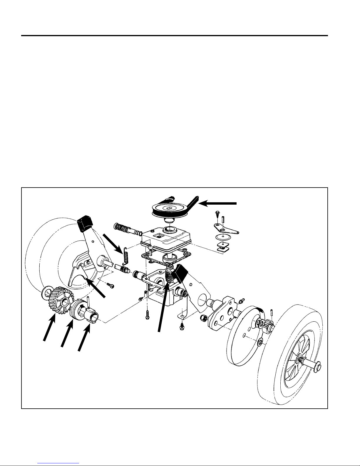
Description
This is a worm and helical gear transmission. The worm
shaft (input shaft) is driven by a belt from the engine
crankshaft. A spring which hooks into the tab on the
front of the transmission (where the roll pin is) and to
the mower housing, pivots the transmission forward to
maintain tension on the belt.
The worm is in constant mesh with the helical gear. The
clutching action is provided by a sliding clutch jaw. A shift
fork moves the clutch jaw to engage and disengage the
transmission. When the clutch jaw engages the helical
gear, power is transferred from the clutch jaw to the
sleeve inside the clutch jaw. The sleeve is pinned to the
axle. The axle then begins to rotate (Fig. 001).
A. Belt E. Shift Fork
B. Spring F. Sleeve
C. Helical Gear G. Input Shaft
D. Clutch Jaw (worm shaft)
A
C
B
E
G
D
F
1-2 WPM Drive Systems Manual
Fig 001 fi g 1
WORM DRIVE TRANSMISSION
Lubrication
This transmission requires 90 wt. gear oil. A variable
weight such as 85w90 is acceptable as long as the
range includes 90 weight. The second part of the
requirement is an EP rating of GL 5 or higher.
The transmission has a fi ll/check plug in the front. With
the transmission level, fi ll until level with the hole. NOTE:
This is equal to about the center of the axle.
Unless the case is cracked, oil can not leak out. Even if
a seal fails, oil will leak out only to the bottom of the seal
on the axle.
If gear failure occurs, the resulting friction can cook the
oil down to a smear in the bottom of the case. This does
not indicate a lack of lubrication.
This type of transmission will last less than 30 minutes
with no lubrication. If a transmission lasts even a few
weeks in consumer use, it had lubrication to start.
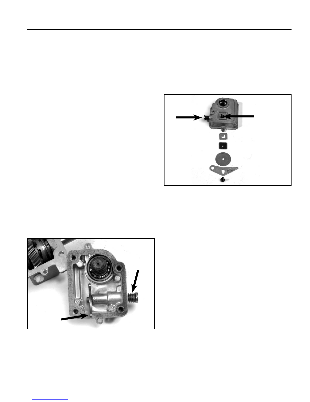
The Shifting Process
The upper end of the clutch fork slides over a groove in
a spring loaded rod. This spring pushes the shift fork and
clutch jaw towards the engaged position (Fig. 002).
The shift rod has a roll pin protruding through the top
of the transmission. This pin goes through a latch plate
with an L shaped slot in it. The slot guides the pin in its
travel from engagement to disengagement. Above the
latch plate is a dust fi lter and a dust cover. The shift arm
on top of the transmission holds all these parts in place
(Fig. 003).
G
A
B
C
D
E
F
Fig 003 3428-0165
A. Roll Pin E. Shift Arm
B. Latch Plate F. Screw
C. Dust Filter G. Shift Rod
D. Dust Cover
A
B
Fig 002 3428-0150
A. Shift Rod B. Shift Fork
When the shift arm is pulled to the rear by the shift
cable, the pin moves to the left side of the mower, then
to the rear. This moves the shift pin, the shift fork, and
the clutch jaw to the disengage position.
NOTE: Dirt packed in the latch plate can prevent
disengagement. The dust fi lter and dust
cover help prevent this failure.
When the shift cable is engaged, tension on the shift
arm is released. The spring on the shift rod applies
pressure to the rod, fork, and clutch jaw to engage the
transmission.
1-3WPM Drive Systems Manual
WORM DRIVE TRANSMISSION
C
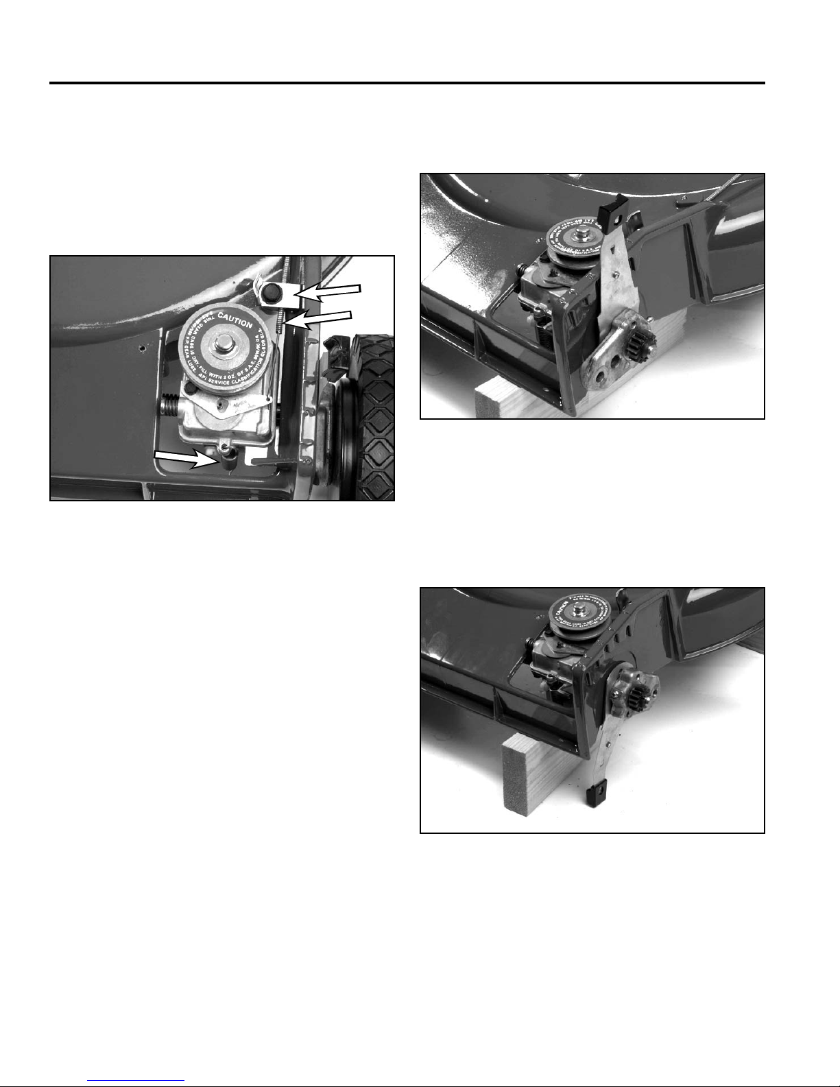
Removal & Installation (front wheel drive
applications)
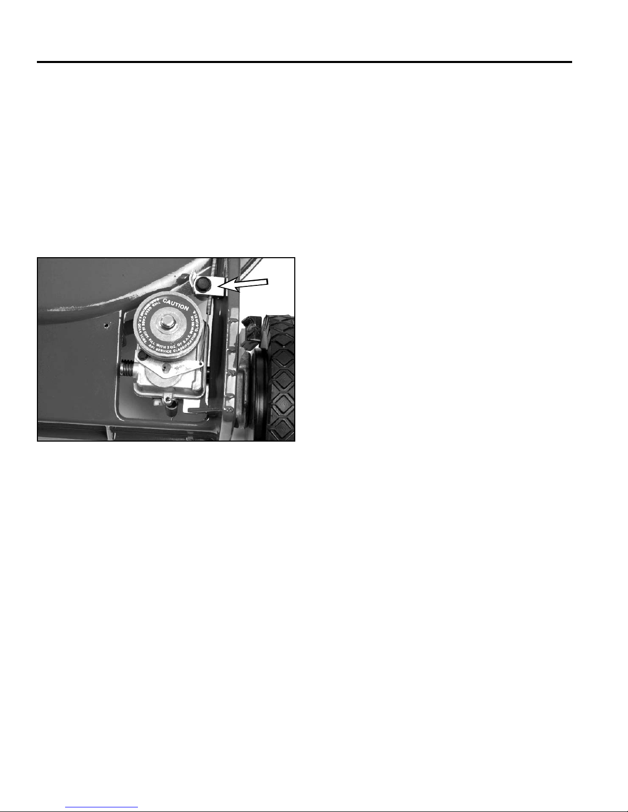
1. Remove the belt cover and unhook the spring on
the front of the transmission. Slip the belt off the
transmission pulley (Fig. 004).
A
B
C
Fig 004 3428-0127
A. Cable Clamp C. Spring
B. Shift Cable
4. Remove both front wheels and wheel covers (Fig.
005).
Fig 005 3428-0129
5. Pivot (both) front spring arms forward until they
point straight down. (This removes the tension from
the pivot arms so the roll pin can be removed) (Fig.
006).
2. Raise the front of the mower off the bench and
support it with blocks.
3. Disconnect the shift cable.
Fig 006 3428-0131
1-4 WPM Drive Systems Manual
WORM DRIVE TRANSMISSION
A
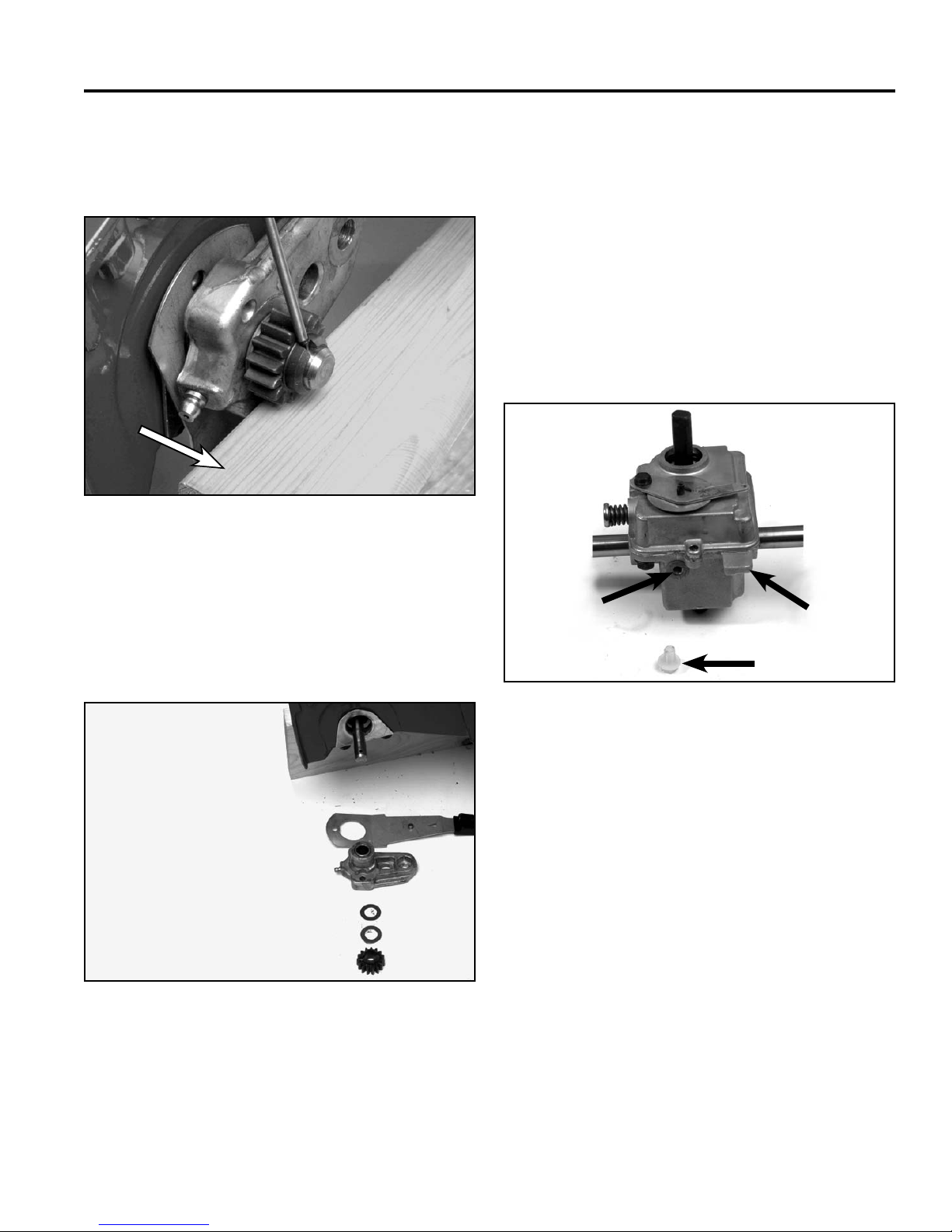
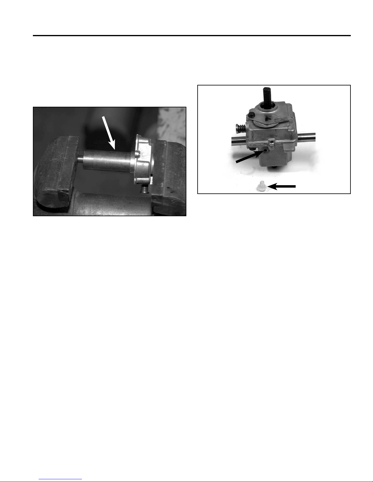
6. Place a block of wood under the wheel pinion for
support and drive the roll pin out of the axle (Fig.
007). Repeat the process on the other side.
A
Fig 007 3428-0135
A. Wood Block
8. Remove the transmission from the chassis.
9. Reverse the procedure to install.
NOTE: Support the wheel pinions with the wood
block while driving the roll pins in. This will
prevent the axle from being bent. Fill the
transmission with oil after it is installed in
the mower (Fig. 009).
Note the front of the transmission is identifi ed by the oil
fi ll/check screw and the fl at tab which is part of the lower
case.
7. The wheel pinion, thrust washer, pivot, and spring
arm will now slide off the end of the axle (Fig. 008).
Repeat the process on the other side.
Fig 008 3428-0137
A
C
B
Fig 009 3428-0166
A. Fill/Check C. Tab
B. Plug
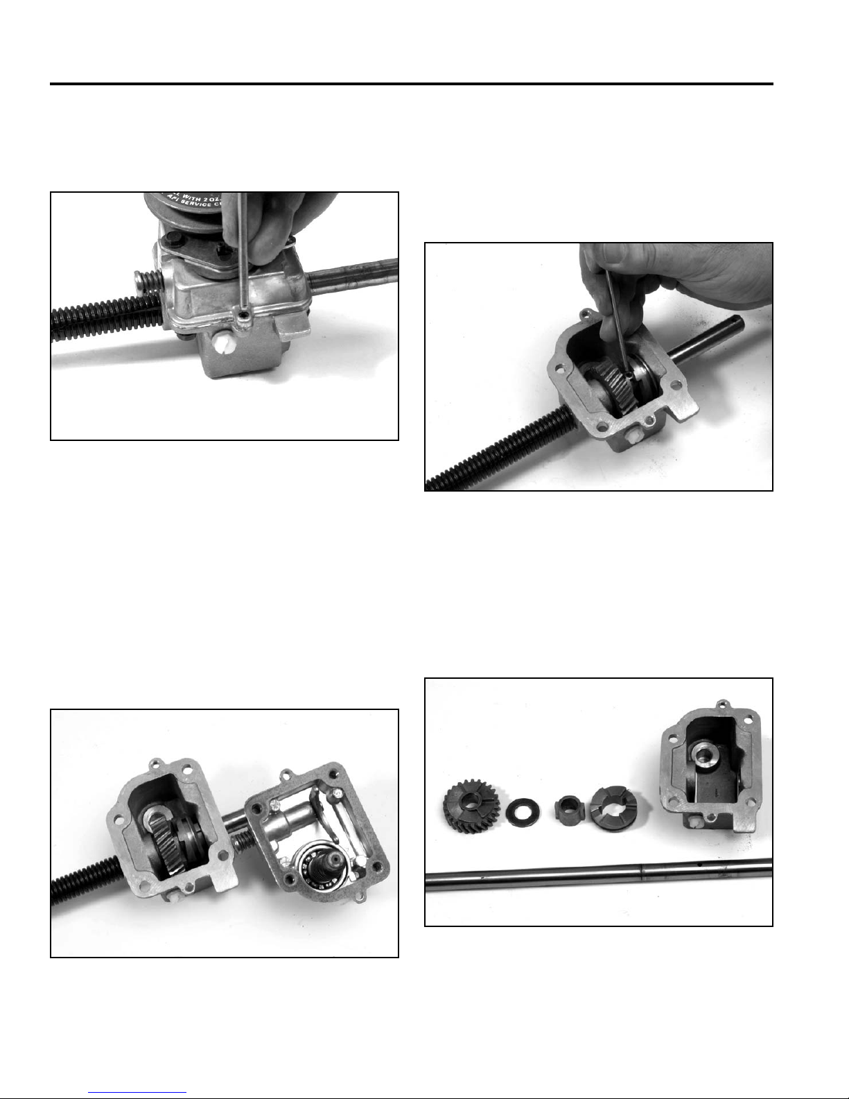
Disassembly
1. Cut and discard the push-on retainer on top of the
transmission pulley. Remove the belt and pulley.
1-5WPM Drive Systems Manual
WORM DRIVE TRANSMISSION
2. Drive the roll pins out of the fl anges in the front
and rear of the case. (These pins align the top and
bottom parts of the case) (Fig. 010).
Fig 010 3428-0146
3. Remove the 4 self-tapping screw that connect the
top and bottom cases.
5. Push the worm shaft out of the cover. This may
require a little pressure.
6. To remove the axle, slide the clutch jaw to the side
and drive the roll pin out of the sleeve and axle (Fig.
012).
Fig 012 3428-0151
Note: If you turn this transmission on its side or
upside down, oil may leak out of the top. This
is not a sealed case.
4. Remove the transmission cover. The shift fork may
come with the cover or may fall into the bottom of
the case (Fig. 011).
Fig 011 3428-0148
7. If the axle bearings are to be re-used, clean the end
of the axle before drawing it out of the case.
8. Remove the sleeve, clutch jaw, helical gear, and
thrust washer (Fig. 013)
A
BC
D
Fig 013 3428-0153
A. Helical Gear C. Sleeve
B. Thrust Washer D. Clutch Jaw
1-6 WPM Drive Systems Manual
WORM DRIVE TRANSMISSION
9. Clean the old gasket material from the mating
surfaces of the case and cover.
10. A hook or small screwdriver can be used to pry the
seals out of the case.
11. An arbor press or large vise will be needed when
removing and replacing the bushings.
12. Clean the oil residue and any metal shavings from
the case.
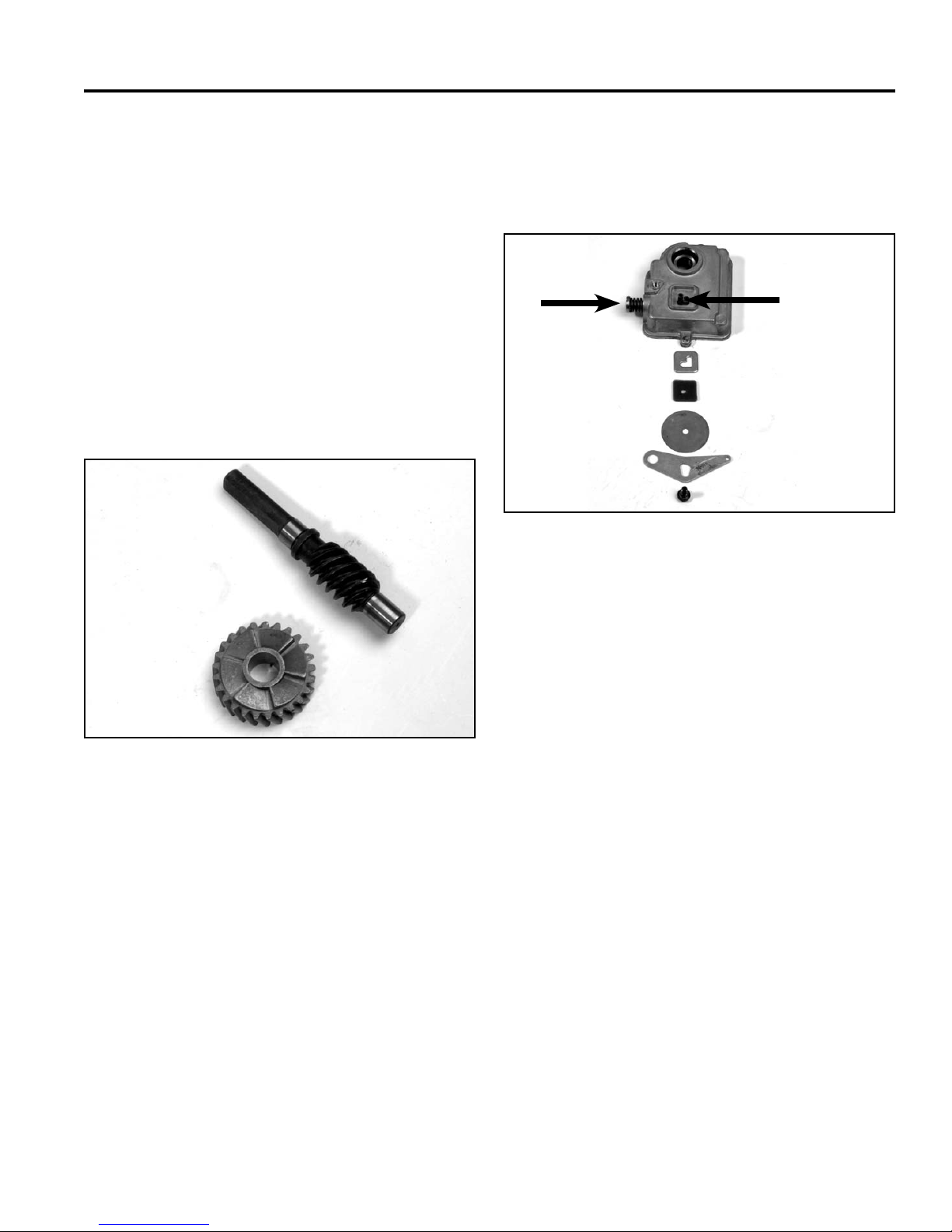
13. Worm and helical gears are sold as a set. Even after
a short run time, they will develop a wear pattern.
Replacing only one gear will result in rapid failure
(Fig. 014).
A
14. Remove the screw from the shift arm and remove
the shift arm, dust cover, and wear plate (Fig. 015). If
the ball bearing is to be replaced, press it out at this
time.
G
A
B
C
D
E
F
Fig 015 3428-0165
A. Roll Pin E. Shift Arm
B. Latch Plate F. Screw
C. Dust Filter G. Shift Rod
D. Dust Cover
B
A. Worm Shaft B. Helical Gear
Fig 014 3428-0157
15. Remove the roll pin and pull shifter rod out of the
cover. Clean the cover.
Assembly
1. Use bushing installation tool P/N 27-0460, to press
in new axle bushings. This tool helps keep the
bushing straight and keeps the inner diameter of the
bushing correctly sized.
1-7WPM Drive Systems Manual

WORM DRIVE TRANSMISSION
Note: The bushings are two different lengths. The
side of the case with the thicker boss uses
a longer busing to support the axle. The
bushings should be fl ush with the inside of
the case (Fig. 016).
A
Fig 016 3428-0158
A. Tool P/N 27-0460
3. Note: Some replacement axles have more than one
hole that can be used to pin the sleeve to the axle.
Refer to the original axle to identify the correct hole
to use. Then drive a roll pin through the sleeve and
axle (Fig. 017).
Fig 017 3428-0151
2. Clean the rust and dirt from the both ends of the
axle. Wipe the inner diameter of the bushings with
a clean cloth. Lightly oil the axle and insert it into
the gearcase. When facing the front of the gearbox,
insert the short end of the axle from left to right.
Install the thrust washer, helical gear, and the sleeve
and clutch jaw. Then push the axle through the other
side of the case.
4. Using a seal protector, slide new seals down each
side of the axle, Install the seal with the lip facing the
transmission. The outer edge of the seal should be
fl ush with the outside of the case. If a seal protector
is not available, wrap a piece of cellophane around
the axle (Fig. 018).
A
B
Fig 018 3428-0170
1-8 WPM Drive Systems Manual
A. Seal protector or B. Seal
Cellophane
WORM DRIVE TRANSMISSION
5. If the bearing in the cover is being replaced, use tool
P/N 27-0490 to press it in place. This bearing only
has one seal. Install the bearing such that the seal
is visible from the top of the cover and the open side
faces the gears. Press the bearing in until it is fully
seated in the case (Fig. 019).
A
Fig 019 3428-0159
9. Fill the transmission with gear oil AFTER it is
installed in the mower. The top of this transmission is
not sealed. It will leak if tipped on its side (Fig. 020).
A
B
Fig 020 3428-0166
A. Fill/Check B. Plug
A. Tool P/N 27-0490
6. Install worm shaft in bearing.
7. Use a new gasket. Install the cover on the bottom
case and start the 4 self-tapping screws. Do not fully
tighten them.
8. Install the front and rear roll pins to align the cover
and case. Then secure the 4 self-tapping screws.
Controls
There are two control cables used with this system. One
cable operates the engine kill switch and fl ywheel brake;
the other controls the transmission.
1-9WPM Drive Systems Manual
WORM DRIVE TRANSMISSION
Adjustment
The transmission cable is a standard lever type. Since
the spring and pin on top of the transmission pushes the
shift fork towards the engaged position, the cable pulls
the shift arm to the rear to disengage the transmission.
The adjustment point is on the mower housing just to
the rear of the transmission. To adjust, pull the control to
the rear (disengage). Go to the cable clamp/adjustment.
Loosen the clamp, pull the cable to the rear until the shift
lever is as far back as it will go. Hold it there and tighten
the clamp (Fig. 021).
A
Fig 021 3428-0127
A. Cable Clamp
1-10 WPM Drive Systems Manual
WORM DRIVE TRANSMISSION
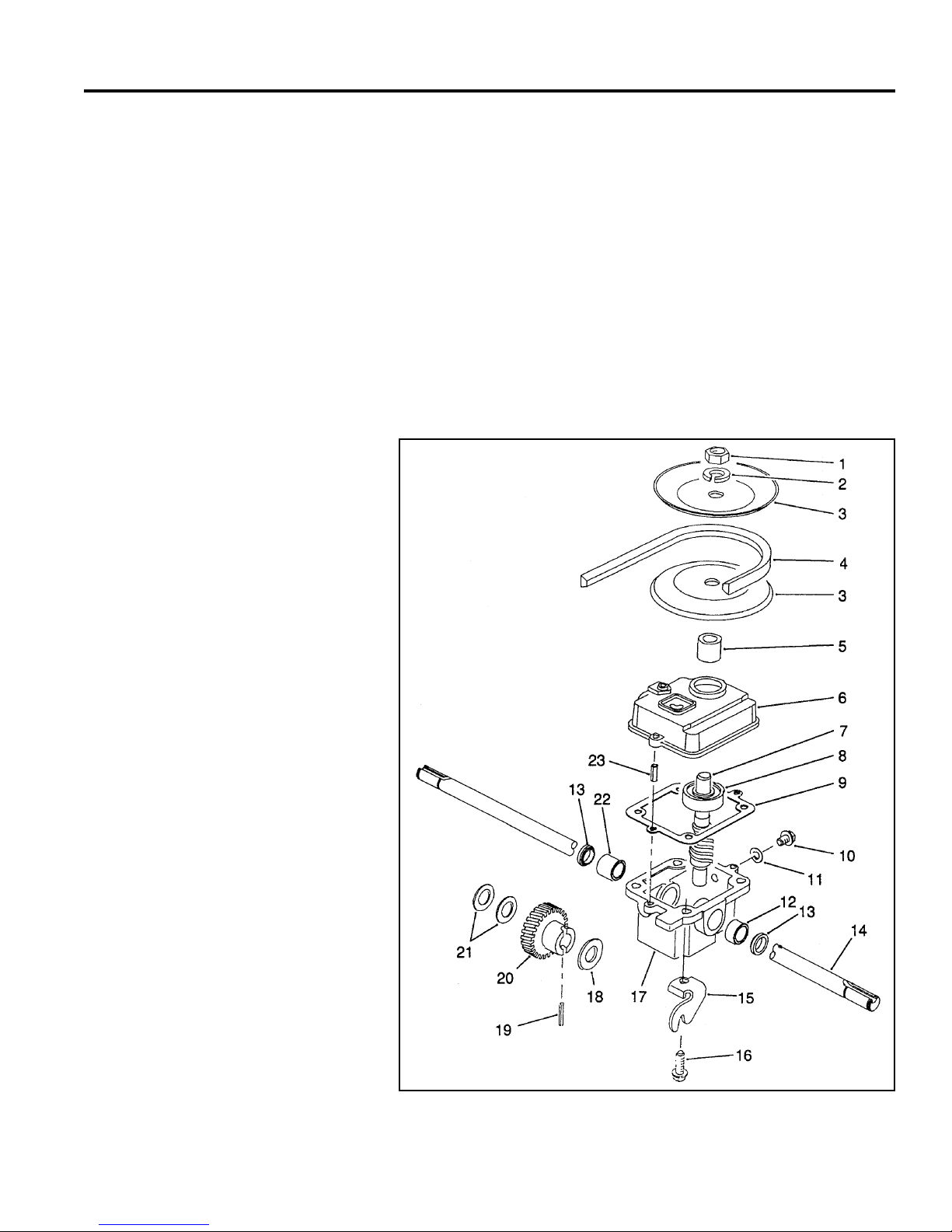
CONSTANT MESH
Description
This transmission is very similar to the “INTERNALLY
CLUTCHED” on page 1 – 1. However, the helical gear
is different as there is no internal clutching (Fig. 022).
Engagement and disengagement is accomplished by
pivoting the transmission to tighten or loosen the belt.
Internal repair procedures are the same, as is the
lubrication requirement, 90 wt. gear oil rated GL-5 or
higher.
1. Jam nut 13. Oil Seal
2. Lock washer 14. Output shaft
3. Half pulley 15. Traction bracket
4. V Belt 16. Thread forming screw
5. Pulley spacer 17. Gearbox case
6. Gearbox cover 18. Thrust washer
7. Shaft & worm 19. Roll pin
8. Ball bearing 20. Helical gear
9. Gearbox gasket 21. Thrust washer
10. Check plug 22. Bushing
11. Gasket check plug 23. Roll pin
12. Bushing
The constant mesh type transmission is used in a 48cm
rear wheel drive application.
Fig 022 fi g 18-A
1-11WPM Drive Systems Manual
WORM DRIVE TRANSMISSION
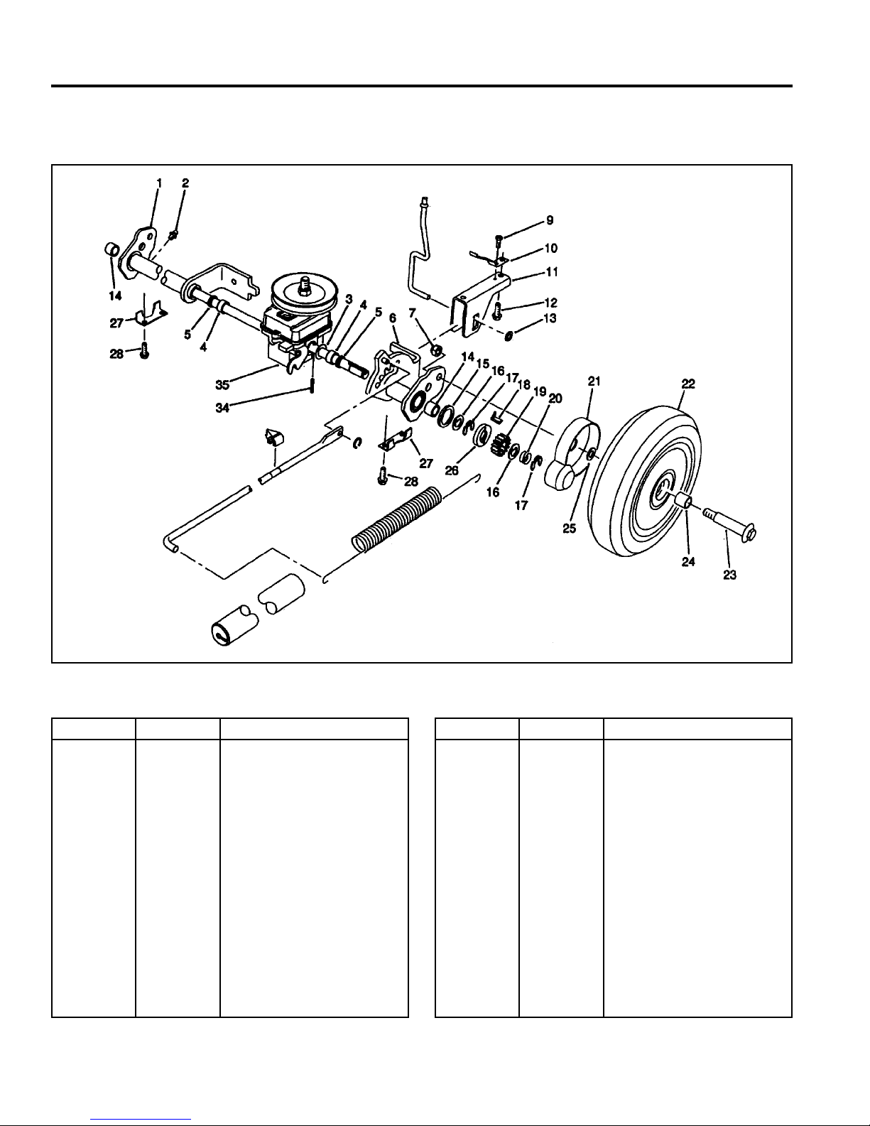
Removal and Installation
Fig 023 20911B sprearaxleassy
Ref. No. Qty Description
1
2
3
4
5
6
7
9
10
11
12
13
14
15
1-12 WPM Drive Systems Manual
1
2
2
2
2
1
2
1
2
1
2
1
2
2
Rear Pivot Assembly RH
(incl. Ref. #2, 4, 5 & 14)
Grease Fitting
Washer
Sleeve Bushing
Grease Seal
Rear Pivot Assembly LH
(incl. Ref. #3, 4, 5 & 14)
Locknut
Thread Forming Screw
Trigger Return Spring
H.O.C. Saddle
Thread Forming Screw
Push Nut
Needle Bearing
Friction Washer
Ref. No. Qty Description
16
17
18
19
20
21
22
23
24
25
26
27
28
34
35
4
4
1
2
2
2
2
2
4
2
2
2
4
2
1
Keyed Thrust Washer
Retaining Ring
LH Rocking Key
Pinion Gear
Compression Spring
Wheel Cover
Tire & Gear Assy Wheel
(incl. Ref. #24)
Wheel Bolt
Wheel Bushing
Wheel Spacer
Clutch Washer
Rear Suspension Plate
Thread Forming Screw
Roll Pin
Gearbox Assembly
 Loading...