

Page 1

WALK BEHIND POWER
MOWER DRIVE SYSTEMS
SERVICE MANUAL
Page 2

Page 3

ABOUT THIS MANUAL
This service manual was written expressly for Toro servicing dealers. The Toro Company has
made every effort to make the information in this manual complete and correct.
This manual was written with the assumption that the reader has basic mechanical knowledge
and skills. This book contains material covering the Toro and Lawn-Boy Walk Behind Mower Drive
Systems models from 1990 through 2006, and may be specifi ed for use on products built after
2006 that are similar in design.
We are hopeful that you will fi nd this manual a valuable addition to your service shop. If you have
any questions or comments regarding this manual, please contact us at the following address:
The Toro Company
LCE Service Training Department
8111 Lyndale Avenue South
Bloomington, MN 55420
The Toro Company reserves the right to change product specifi cations or this manual without
notice.
Copyright© All Rights Reserved
©2006 The Toro Company
Page 4

THIS PAGE INTENTIONALLY LEFT BLANK.
Page 5

TABLE OF CONTENTS
QUICK REFERENCE
Transmission Remove and Replace
3 speed transmission . . . . . . . . . . . . . . . . . . . . . . . . . . . . . . . . .
21” steel & cast deck Personal Pace, Easy Stride transmission . . . . . . . . . . . . . . . .
22” steel deck transmission, Toro and Lawn-Boy . . . . . . . . . . . . . . . . . . . . . .
21” Lawn-Boy Insight . . . . . . . . . . . . . . . . . . . . . . . . . . . . . . . . .
Transmission Internal Repair
3 speed transmission . . . . . . . . . . . . . . . . . . . . . . . . . . . . . . . . .
Spur/Bevel gear transmission . . . . . . . . . . . . . . . . . . . . . . . . . . . . . .
Bevel gear transmission . . . . . . . . . . . . . . . . . . . . . . . . . . . . . . . .
Wheel Clutch Troubleshooting & Repair
Rocking Key style . . . . . . . . . . . . . . . . . . . . . . . . . . . . . . . . . .
Spring Ratchet style . . . . . . . . . . . . . . . . . . . . . . . . . . . . . . . . .
Blade Clutch System Troubleshooting & Repair
Blade Brake Clutch System . . . . . . . . . . . . . . . . . . . . . . . . . . . . . .
Blade Override System (Toro - BOS) Blade Clutch System (Lawn-Boy - BCS) . . . . . . . . . . .
4-5
2-3
3-10
3-20
4-6
2-4
3-16
5-2
5-9
6-2
6-28
Handle Disassembly
Toro 2 Bail handle . . . . . . . . . . . . . . . . . . . . . . . . . . . . . . . . . .
Personal Pace Easy Stride (Generation 1) . . . . . . . . . . . . . . . . . . . . . . . . .
Personal Pace Easy Stride (Generation 2) . . . . . . . . . . . . . . . . . . . . . . . . .
Lawn-Boy Sens-a-Speed . . . . . . . . . . . . . . . . . . . . . . . . . . . . . . .
Belt Replacement
Mowers with Toro Blade Brake Clutch . . . . . . . . . . . . . . . . . . . . . . . . . .
Mowers with Toro Blade Override System . . . . . . . . . . . . . . . . . . . . . . . . .
Zone start 21” Rear Wheel Drive Toro & Lawn-Boy (except Insight) . . . . . . . . . . . . . . .
Zone start 22” Toro Rear Wheel Drive . . . . . . . . . . . . . . . . . . . . . . . . . .
Zone start 22” Toro Front Wheel Drive . . . . . . . . . . . . . . . . . . . . . . . . . .
Lawn-Boy Insight Zone Start . . . . . . . . . . . . . . . . . . . . . . . . . . . . . .
Lawn-Boy Insight with Blade Clutch System . . . . . . . . . . . . . . . . . . . . . . . .
7-2
7-3
7-6
7-9
8-3
8-3
8-2
3-10
3-5
3-19
8-3
iWPM Drive Systems Manual
Page 6

TABLE OF CONTENTS
WORM DRIVE TRANSMISSION
GENERAL
INTERNALLY CLUTCHED
Description . . . . . . . . . . . . . . . . . . . . . . . . . . . . . . . . . . .
Lubrication . . . . . . . . . . . . . . . . . . . . . . . . . . . . . . . . . . .
The Shifting Process . . . . . . . . . . . . . . . . . . . . . . . . . . . . . . .
Removal & Installation (front wheel drive applications) . . . . . . . . . . . . . . . . . .
Disassembly . . . . . . . . . . . . . . . . . . . . . . . . . . . . . . . . . . .
Assembly . . . . . . . . . . . . . . . . . . . . . . . . . . . . . . . . . . . .
Controls . . . . . . . . . . . . . . . . . . . . . . . . . . . . . . . . . . . .
Adjustment . . . . . . . . . . . . . . . . . . . . . . . . . . . . . . . . . . .
CONSTANT MESH
Description . . . . . . . . . . . . . . . . . . . . . . . . . . . . . . . . . . .
Removal & Installation . . . . . . . . . . . . . . . . . . . . . . . . . . . . . . .
Controls . . . . . . . . . . . . . . . . . . . . . . . . . . . . . . . . . . . .
WHEEL CLUTCH . . . . . . . . . . . . . . . . . . . . . . . . . . . . . . . . . .
SINGLE SPEED SPUR/BEVEL GEAR TRANSMISSION
GEAR CASE ASSEMBLY . . . . . . . . . . . . . . . . . . . . . . . . . . . . . . .
Description . . . . . . . . . . . . . . . . . . . . . . . . . . . . . . . . . . .
Lubrication . . . . . . . . . . . . . . . . . . . . . . . . . . . . . . . . . . .
Transmission Remove & Replace . . . . . . . . . . . . . . . . . . . . . . . . . .
Transmission Internal Repair . . . . . . . . . . . . . . . . . . . . . . . . . . . .
Assembly . . . . . . . . . . . . . . . . . . . . . . . . . . . . . . . . . . . .
1-2
1-3
1-3
1-4
1-5
1-7
1-9
1-10
1-11
1-12
1-13
1-14
2-2
2-3
2-3
2-3
2-4
2-5
SINGLE SPEED BEVEL GEAR TRANSMISSION
EXPLODED VIEW - SINGLE SPEED BEVEL GEAR TRANSMISSION . . . . . . . . . . . . . .
GENERAL INFORMATION . . . . . . . . . . . . . . . . . . . . . . . . . . . . . . .
FRONT AXLE & TRANSMISSION ASSEMBLY . . . . . . . . . . . . . . . . . . . . . . .
22” FRONT WHEEL DRIVE MODELS
Remove Transmission . . . . . . . . . . . . . . . . . . . . . . . . . . . . . . .
Transmission Disassembly . . . . . . . . . . . . . . . . . . . . . . . . . . . . .
Transmission Assembly . . . . . . . . . . . . . . . . . . . . . . . . . . . . . .
Assembly Tips . . . . . . . . . . . . . . . . . . . . . . . . . . . . . . . . . .
Belt Service - Front Wheel Drive Models . . . . . . . . . . . . . . . . . . . . . . . .
22” TORO & LAWN-BOY REAR WHEEL DRIVE MODELS
Transmission Removal & Belt Replacement . . . . . . . . . . . . . . . . . . . . . .
Rear Axle Disassembly . . . . . . . . . . . . . . . . . . . . . . . . . . . . . .
Transmission Disassembly . . . . . . . . . . . . . . . . . . . . . . . . . . . . .
Transmission Assembly . . . . . . . . . . . . . . . . . . . . . . . . . . . . . .
Axle Assembly Tips . . . . . . . . . . . . . . . . . . . . . . . . . . . . . . . .
LAWN-BOY INSIGHT TRANSMISSION REMOVE & REPLACE . . . . . . . . . . . . . . . .
Tranmission Removal & Belt Replacement . . . . . . . . . . . . . . . . . . . . . . .
Transmission Disassembly . . . . . . . . . . . . . . . . . . . . . . . . . . . . .
Transmission Assembly . . . . . . . . . . . . . . . . . . . . . . . . . . . . . . .
Axle Assembly Tips . . . . . . . . . . . . . . . . . . . . . . . . . . . . . . . .
Transmission Installation Tips . . . . . . . . . . . . . . . . . . . . . . . . . . . .
THREE SPEED TRANSMISSION
GEAR CASE ASSEMBLY . . . . . . . . . . . . . . . . . . . . . . . . . . . . . . .
OPERATION
Input System . . . . . . . . . . . . . . . . . . . . . . . . . . . . . . . . . .
3-2
3-3
3-4
3-5
3-7
3-7
3-8
3-9
3-10
3-15
3-16
3-16
3-17
3-19
3-20
3-24
3-24
3-24
3-25
4-2
4-3
ii WPM Drive Systems Manual
Page 7

TABLE OF CONTENTS
Speed Reduction System . . . . . . . . . . . . . . . . . . . . . . . . . . . . . .
Gear Selection System . . . . . . . . . . . . . . . . . . . . . . . . . . . . . .
Removal - Toro Vacu Power/Lawn-Boy Medallion Models . . . . . . . . . . . . . . . . .
Removal - Recycler/Rear Bagger Chassis . . . . . . . . . . . . . . . . . . . . . . .
Alternate Method . . . . . . . . . . . . . . . . . . . . . . . . . . . . . . . . .
Disassembly . . . . . . . . . . . . . . . . . . . . . . . . . . . . . . . . . . .
Transmission - Assembly . . . . . . . . . . . . . . . . . . . . . . . . . . . . . .
Output Shaft Assembly . . . . . . . . . . . . . . . . . . . . . . . . . . . . . . .
Input Shaft Assembly . . . . . . . . . . . . . . . . . . . . . . . . . . . . . . .
Intermediate Shaft Assembly . . . . . . . . . . . . . . . . . . . . . . . . . . . .
Installation . . . . . . . . . . . . . . . . . . . . . . . . . . . . . . . . . . .
Special Assembly Notes for Toro Vacu Power/Lawn-Boy Medallion . . . . . . . . . . . . .
TROUBLESHOOTING TIPS - 3 SPEED TRANSMISSION
Hard Shifting . . . . . . . . . . . . . . . . . . . . . . . . . . . . . . . . . . .
Slipping Gears . . . . . . . . . . . . . . . . . . . . . . . . . . . . . . . . . .
WHEEL PINION CLUTCH
GEAR CASE & WHEEL ASSEMBLY, ROCKING KEY STYLE . . . . . . . . . . . . . . . . .
Wheel Pinion Clutch . . . . . . . . . . . . . . . . . . . . . . . . . . . . . . . .
Component Defi nitions . . . . . . . . . . . . . . . . . . . . . . . . . . . . . . .
Test for Function . . . . . . . . . . . . . . . . . . . . . . . . . . . . . . . . .
Quick Test . . . . . . . . . . . . . . . . . . . . . . . . . . . . . . . . . . . .
Rear Height-of-Cut & Wheel Pinion Clutch - Disassembly . . . . . . . . . . . . . . . . .
Rear Height-of-Cut & Wheel Pinion Clutch - Assembly . . . . . . . . . . . . . . . . . .
GEAR CASE & WHEEL ASSEMBLY SPRING RATCHET STYLE . . . . . . . . . . . . . . . .
Spring Ratchet Key Style . . . . . . . . . . . . . . . . . . . . . . . . . . . . . .
Servicing the System . . . . . . . . . . . . . . . . . . . . . . . . . . . . . . .
WHEEL PINION SERVICE . . . . . . . . . . . . . . . . . . . . . . . . . . . . . . .
4-3
4-4
4-5
4-6
4-6
4-6
4-7
4-8
4-9
4-10
4-10
4-11
4-12
4-12
5-2
5-3
5-3
5-4
5-4
5-4
5-5
5-8
5-9
5-9
5-9
BLADE BRAKE CLUTCH SYSTEMS (BBC), BLADE OVERRIDE SYSTEM (BOS),
BLADE CLUTCH SYSTEM (BCS)
BLADE BRAKE CLUTCH SYSTEM
Description . . . . . . . . . . . . . . . . . . . . . . . . . . . . . . . . . . .
BBC Clutch Option . . . . . . . . . . . . . . . . . . . . . . . . . . . . . . . .
Control Box Operation . . . . . . . . . . . . . . . . . . . . . . . . . . . . . . .
Handle Controls . . . . . . . . . . . . . . . . . . . . . . . . . . . . . . . . .
Control Box Disassembly . . . . . . . . . . . . . . . . . . . . . . . . . . . . . .
Control Box Assembly . . . . . . . . . . . . . . . . . . . . . . . . . . . . . . .
TORO BBC SERVICE GUIDE . . . . . . . . . . . . . . . . . . . . . . . . . . . . . .
BLADE BRAKE CLUTCH ASSEMBLY (Toro Vacu Power/Lawn-Boy Medallion) . . . . . . . . . .
TORO VACU POWER/LAWN-BOY MEDALLION BBC . . . . . . . . . . . . . . . . . . . .
Bellcrank System Disassembly (Toro Vacu Power/Lawn-Boy Medallion) . . . . . . . . . . .
Bellcrank System Assembly (Toro Vacu Power/Lawn-Boy Medallion) . . . . . . . . . . . . .
BBC Cover and Screen . . . . . . . . . . . . . . . . . . . . . . . . . . . . . .
Under Deck Components Disassembly (Toro Vacu Power/Lawn-Boy Medallion) . . . . . . . .
Under Deck Components Assembly (Toro Vacu Power/Lawn-Boy Medallion) . . . . . . . . . .
BBC Cable Removal (Toro Vacu Power/Lawn-Boy Medallion) . . . . . . . . . . . . . . .
BBC Cable Installation (Toro Vacu Power/Lawn-Boy Medallion) . . . . . . . . . . . . . . .
ENGINE & BLADE ASSEMBLY (Toro Recycler/Rear Bagger) . . . . . . . . . . . . . . . . .
TORO RECYCLER/REAR BAGGER BBC . . . . . . . . . . . . . . . . . . . . . . . . .
Idler Arm System Disassembly (Recycler/Rear Bagger) . . . . . . . . . . . . . . . . . .
Idler Arm System Assembly (Recycler/Rear Bagger) . . . . . . . . . . . . . . . . . . .
6-2
6-2
6-2
6-3
6-6
6-7
6-10
6-11
6-12
6-12
6-13
6-14
6-15
6-17
6-19
6-20
6-21
6-22
6-22
6-25
iiiWPM Drive Systems Manual
Page 8

TABLE OF CONTENTS
BBC Cable Removal (Recycler/Rear Bagger) . . . . . . . . . . . . . . . . . . . . . .
BBC Cable Installation (Recycler/Rear Bagger) . . . . . . . . . . . . . . . . . . . . .
BLADE OVERRIDE SYSTEM (BOS), BLADE CLUTCH SYSTEM (BCS) . . . . . . . . . . . . .
Disassembly . . . . . . . . . . . . . . . . . . . . . . . . . . . . . . . . . . .
Brake Arm Assembly . . . . . . . . . . . . . . . . . . . . . . . . . . . . . . .
BOS/BCS System Assembly . . . . . . . . . . . . . . . . . . . . . . . . . . . .
HANDLES AND CONTROL CABLES
Toro 2 Bail Handle . . . . . . . . . . . . . . . . . . . . . . . . . . . . . . . . .
Personal Pace Generation 1/Easy Stride Generation 1 . . . . . . . . . . . . . . . . . .
Operation . . . . . . . . . . . . . . . . . . . . . . . . . . . . . . . . . . . .
Disassembly . . . . . . . . . . . . . . . . . . . . . . . . . . . . . . . . . . .
Reassembly . . . . . . . . . . . . . . . . . . . . . . . . . . . . . . . . . . .
Adjusting the Personal Pace Cable . . . . . . . . . . . . . . . . . . . . . . . . . .
Personal Pace Generation 2/Easy Stride Generation 2 . . . . . . . . . . . . . . . . . .
Handle Removal . . . . . . . . . . . . . . . . . . . . . . . . . . . . . . . . .
Adjusting the Personal Pace/Easy Stride Cable . . . . . . . . . . . . . . . . . . . . .
Lawn-Boy 2 Bail Handle . . . . . . . . . . . . . . . . . . . . . . . . . . . . . .
Lawn-Boy Sens-a-Speed . . . . . . . . . . . . . . . . . . . . . . . . . . . . . .
Operation . . . . . . . . . . . . . . . . . . . . . . . . . . . . . . . . . . . .
Handle Disassembly, Zone Start Models . . . . . . . . . . . . . . . . . . . . . . . .
Assembly . . . . . . . . . . . . . . . . . . . . . . . . . . . . . . . . . . . .
Cable Adjustment . . . . . . . . . . . . . . . . . . . . . . . . . . . . . . . . .
Self-Propel Cable . . . . . . . . . . . . . . . . . . . . . . . . . . . . . . . . .
Handle Disassembly, Lawn-Boy Blade Clutch System (BCS) Models . . . . . . . . . . . . .
3 Speed Transmission Models . . . . . . . . . . . . . . . . . . . . . . . . . . . .
3 Speed Control Cables . . . . . . . . . . . . . . . . . . . . . . . . . . . . . .
BBC Cable Adjustment (Toro Vacu Power/Lawn-Boy Medallion) . . . . . . . . . . . . . . .
Toro BBC Cable Adjustment (Recycler/Rear Bagger) . . . . . . . . . . . . . . . . . . .
Toro BOS Control . . . . . . . . . . . . . . . . . . . . . . . . . . . . . . . . .
Toro BOS Control Cable Adjustment . . . . . . . . . . . . . . . . . . . . . . . . .
Lawn-Boy BCS Control . . . . . . . . . . . . . . . . . . . . . . . . . . . . . . .
Lawn-Boy BCS Control Cable Adjustment . . . . . . . . . . . . . . . . . . . . . . .
6-27
6-28
6-28
6-28
6-32
6-33
7-2
7-3
7-3
7-3
7-5
7-6
7-6
7-6
7-8
7-8
7-9
7-9
7-9
7-10
7-11
7-11
7-11
7-13
7-13
7-15
7-16
7-17
7-18
7-18
7-18
SELF-PROPEL BELT REPLACEMENT
Toro 21” Front Wheel Drive . . . . . . . . . . . . . . . . . . . . . . . . . . . . .
22” Front Wheel Drive . . . . . . . . . . . . . . . . . . . . . . . . . . . . . . .
22” Rear Wheel Drive . . . . . . . . . . . . . . . . . . . . . . . . . . . . . . .
21” Steel & Cast Deck Toro & Lawn-Boy Mowers Belt Replacement . . . . . . . . . . . . .
21” Cast Deck Mowers with 3 Speed Transmission . . . . . . . . . . . . . . . . . . . .
21” Toro & Lawn-Boy Mowers with Blade Brake Clutch . . . . . . . . . . . . . . . . . .
21” Toro Mowers with Blade Override System & Lawn-Boy Mower
with Blade Brake Clutch System . . . . . . . . . . . . . . . . . . . . . . . . .
21” Lawn-Boy Insight Mowers . . . . . . . . . . . . . . . . . . . . . . . . . . . .
iv WPM Drive Systems Manual
8-2
8-2
8-2
8-2
8-2
8-3
8-3
8-3
Page 9

TABLE OF CONTENTS
Using this manual
Following each model number in the list below are codes identifying the type of
deck material, transmission, wheel pinion clutch, hand controls, and if it has a
blade clutch system. Use this information to select the correct sections of the
service manual for the mower being serviced.
Code List
1B - one bail CDVP - cast deck Vacu Power
2B - two bail ES1 - Easy Stride 1st generation
3S- 3 speed ES2 - Easy Stride 2nd generation
21” stl - 21” steel deck Ins - Insight
22” stl - 22” steel deck PP1 - Personal Pace 1st generation
B- bevel gear PP2 - Personal Pace 2nd generation
BBC - blade brake clutch RK - rocking key
BBC VP - blade brake clutch SB - spur bevel
for Vacu Power SR - spring ratchet
BOS - blade override system SS - Sens-a-Speed
CD - cast deck W - worm
Model Trans Trans Wheel Handle Blade
R&R Internal Pinion Repair Clutch
Repair
10301 CD SB RK 2B None
10302 CD SB RK 2B None
10304 CD SB RK 2B None
10305 CD SB RK 2B None
10307 CD SB RK 2B None
10309 CD SB RK 2B None
10310 CD SB RK 2B None
10311 CD SB RK 2B None
10312 CD SB RK 2B None
10313 CD SB RK 2B None
10314 CD SB RK 2B None
10316 CD SB RK 2B None
10317 CD SB RK 2B None
10318 CD SB RK 2B None
10319 CD SB RK 2B None
10320 CD SB RK 2B None
10321 CD SB RK 2B None
10323 CD SB RK 2B None
10324 CD SB RK 2B None
10324C CD SB RK 2B None
10327 CD SB RK 2B None
10328 CD SB RK 2B None
10329 CD SB RK 2B None
10330 CD SB RK 2B None
vWPM Drive Systems Manual
Page 10

TABLE OF CONTENTS
1B - one bail CDVP - cast deck Vacu Power
2B - two bail ES1 - Easy Stride 1st generation
3S- 3 speed ES2 - Easy Stride 2nd generation
21” stl - 21” steel deck Ins - Insight
22” stl - 22” steel deck PP1 - Personal Pace 1st generation
B- bevel gear PP2 - Personal Pace 2nd generation
BBC - blade brake clutch RK - rocking key
BBC VP - blade brake clutch SB - spur bevel
for Vacu Power SR - spring ratchet
BOS - blade override system SS - Sens-a-Speed
CD - cast deck W - worm
Model Trans Trans Wheel Handle Blade
R&R Internal Pinion Repair Clutch
Repair
10331 CD SB RK 2B None
10332 CD SB RK 2B None
10334 CD SB RK 2B None
10335 CD SB RK 2B None
10342 CD SB RK 2B None
10343 CD SB RK 2B None
10344 CD SB RK 2B None
10345 CD SB RK 2B None
10356 CD SB RK 2B None
10357 CD SB RK 2B None
10358 CD SB RK 2B None
10359C CD SB RK 2B None
10360 CD SB RK 2B None
10360C CD SB RK 2B None
10361 CD SB RK 2B None
10362 CD SB RK 2B None
10363 CD SB RK 2B None
10515 CD 3S RK 2B None
10516 CD 3S RK 2B None
10517 CD 3S RK 2B None
10518 CD 3S RK 2B None
10519 CD 3S RK 2B None
10520 CD 3S RK 2B None
10521 CD 3S RK 2B None
10522 CD 3S RK 2B None
10523 CD 3S RK 2B None
10524 CD 3S RK 2B None
10525 CD 3S RK 2B None
10527 CD 3S RK 2B None
10528 CD 3S RK 2B None
10533 CD 3S RK BBC BBC VP
10545 CD 3S RK 2B None
Code List
vi WPM Drive Systems Manual
Page 11

TABLE OF CONTENTS
1B - one bail CDVP - cast deck Vacu Power
2B - two bail ES1 - Easy Stride 1st generation
3S- 3 speed ES2 - Easy Stride 2nd generation
21” stl - 21” steel deck Ins - Insight
22” stl - 22” steel deck PP1 - Personal Pace 1st generation
B- bevel gear PP2 - Personal Pace 2nd generation
BBC - blade brake clutch RK - rocking key
BBC VP - blade brake clutch SB - spur bevel
for Vacu Power SR - spring ratchet
BOS - blade override system SS - Sens-a-Speed
CD - cast deck W - worm
Model Trans Trans Wheel Handle Blade
R&R Internal Pinion Repair Clutch
Repair
10546 CD 3S RK 2B None
10547 CD 3S RK 2B None
10548 CD 3S RK 2B None
10550 CD SB RK ES1 None
10551 CD SB RK ES1 None
10552 CD SB RK ES1 None
10655 22stl B SR ES2 None
10656 22stl B SR ES2 None
10672 Ins B SR SS None
10673 Ins B SR SS None
10682 Ins B SR 2B None
10684 Ins B SR 2B None
10684C Ins B SR 2B None
10685 Ins B SR SS None
10686 Ins B SR SS None
10686C Ins B SR SS None
10687 Ins B SR SS BCS
10695 Ins B SR SS None
10696 Ins B SR SS None
10696C Ins B SR SS None
10697 Ins B SR SS BCS
10910 CD SB RK 2B None
10910B CD SB RK 2B None
10926 CD SB RK 2B None
10927 CD SB RK 2B None
10928 CD 3S RK ? None
10929 CD SB RK 2B None
10995 Ins B SR SS None
10997 CD B SR SS BCS
11001 CD 3S RK 2B None
11001B CD 3S RK 2B None
11003 CD 3S RK 2B None
Code List
viiWPM Drive Systems Manual
Page 12

TABLE OF CONTENTS
1B - one bail CDVP - cast deck Vacu Power
2B - two bail ES1 - Easy Stride 1st generation
3S- 3 speed ES2 - Easy Stride 2nd generation
21” stl - 21” steel deck Ins - Insight
22” stl - 22” steel deck PP1 - Personal Pace 1st generation
B- bevel gear PP2 - Personal Pace 2nd generation
BBC - blade brake clutch RK - rocking key
BBC VP - blade brake clutch SB - spur bevel
for Vacu Power SR - spring ratchet
BOS - blade override system SS - Sens-a-Speed
CD - cast deck W - worm
Model Trans Trans Wheel Handle Blade
R&R Internal Pinion Repair Clutch
Repair
16212 W Worm None None None
16212B W Wom None None None
16212W W Worm None None None
16212WG W Worm None None None
16401 W Worm None None None
16402 W Worm None None None
16404 W Worm None None None
16411 W Worm None None None
16775 W Worm None None None
16776 W Worm None None None
16785 W Worm None None None
16793 W Worm None None None
20001 22stl B SR 2B None
20003 22stl B SR 2B None
20005 22stl B SR 2B None
20007 22stl B SR 2B None
20011 22stl SB RK 2B None
20012 22stl B SR 2B None
20013 22stl B SR PP2 None
20014 22stl B SR PP2 None
20016 22stl B SR 2B None
20017 22stl B SR PP2 None
20018 22stl B SR PP2 None
20019 22stl B SR 2B None
20020 CD SB RK 2B None
20021 CD SB RK 2B None
20028 CD SB RK 2B None
20031 22stl B SR PP2 None
20036 CD SB RK PP2 None
20037 CD SB RK PP2 None
20038 CD SB RK PP2 None
20039 CD SB RK PP2 None
Code List
viii WPM Drive Systems Manual
Page 13

TABLE OF CONTENTS
Code List
1B - one bail CDVP - cast deck Vacu Power
2B - two bail ES1 - Easy Stride 1st generation
3S- 3 speed ES2 - Easy Stride 2nd generation
21” stl - 21” steel deck Ins - Insight
22” stl - 22” steel deck PP1 - Personal Pace 1st generation
B- bevel gear PP2 - Personal Pace 2nd generation
BBC - blade brake clutch RK - rocking key
BBC VP - blade brake clutch SB - spur bevel
for Vacu Power SR - spring ratchet
BOS - blade override system SS - Sens-a-Speed
CD - cast deck W - worm
Model Trans Trans Wheel Handle Blade
R&R Internal Pinion Repair Clutch
Repair
20041 22stl B SR PP2 None
20044 CD 3SP RK 1B None
20047 22stl B RK PP2 None
20049 22stl B SR PP2 None
20051 22stl B SR PP2 None
20054 CD SB RK PP2 None
20055 CD SB RK PP2 None
20056 CD SB RK PP2 BOS
20057 CD SB RK PP2 None
20058 CD SB RK PP2 BOS
20070 22stl B SR PP2 None
20079 22stl B SR PP2 None
20106 CD 3SP RK 1B BBC
20107 CD 3SP RK 1B BBC
20210 CD 3SP RK 1B BBC
20211 CD 3SP RK 1B BBC
20214 CD 3SP RK 1B None
20216 CD 3SP RK 1B None
20218 CD 3SP RK 1B None
20219 CD 3SP RK 1B BBC
20320 CD 3SP RK 1B None
20321 CD 3SP RK 1B None
20322 CD 3SP RK 1B None
20324 CD 3SP RK 1BBC BBC
20325 CD 3SP RK BBC BBC
20327B CD 3SP RK 1B None
20328B CD 3SP RK 1B None
20436 CD 3SP RK 1B None
20436WF CD 3SP RK 1B None
20437 CD 3SP RK 1B None
20438 CD 3SP RK BBC BBC
20438WF CD 3SP RK BBC BBC
ixWPM Drive Systems Manual
Page 14

TABLE OF CONTENTS
1B - one bail CDVP - cast deck Vacu Power
2B - two bail ES1 - Easy Stride 1st generation
3S- 3 speed ES2 - Easy Stride 2nd generation
21” stl - 21” steel deck Ins - Insight
22” stl - 22” steel deck PP1 - Personal Pace 1st generation
B- bevel gear PP2 - Personal Pace 2nd generation
BBC - blade brake clutch RK - rocking key
BBC VP - blade brake clutch SB - spur bevel
for Vacu Power SR - spring ratchet
BOS - blade override system SS - Sens-a-Speed
CD - cast deck W - worm
Model Trans Trans Wheel Handle Blade
R&R Internal Pinion Repair Clutch
Repair
20439 CD 3SP RK BBC BBC
20439WF CD 3SP RK BBC BBC
20462 CD 3SP RK 1B None
20463 CD 3SP RK 1B None
20464 CD 3SP RK 1B None
20465 CD 3SP RK BBC BBC
20466 CD 3SP RK BBC BBC
20470 CD 3SP RK 1B None
20472 CD 3SP RK 1B None
20473 CD 3SP RK 1B None
20474 CD 3SP RK 1B None
20475 CD 3SP RK BBC BBC
20476 CD 3SP RK BBC BBC
20478 CD 3SP RK 1B None
20479 CD 3SP RK 1B None
20480 CD 3SP RK 1B None
20481 CD 3SP RK 1B None
20482 CD 3SP RK BBC BBC
20483 CD 3SP RK BBC BBC
20486 CD 3SP RK 1B None
20487 CD 3SP RK BBC BBC
20488 CD 3SP RK 1B None
20489 CD 3SP RK 1B None
20490 CD 3SP RK BBC BBC
20494 CD 3SP RK 1B None
20495 CD 3SP RK 1B None
20622 CD 3SP RK BBC BBC
20632 CD 3SP RK BBC BBC
20652 21” stl SB RK PP1 None
20654 21” stl SB RK PP2 None
20655 22” stl B SR PP2 None
20656 22” stl B SR PP2 None
Code List
x WPM Drive Systems Manual
Page 15

TABLE OF CONTENTS
1B - one bail CDVP - cast deck Vacu Power
2B - two bail ES1 - Easy Stride 1st generation
3S- 3 speed ES2 - Easy Stride 2nd generation
21” stl - 21” steel deck Ins - Insight
22” stl - 22” steel deck PP1 - Personal Pace 1st generation
B- bevel gear PP2 - Personal Pace 2nd generation
BBC - blade brake clutch RK - rocking key
BBC VP - blade brake clutch SB - spur bevel
for Vacu Power SR - spring ratchet
BOS - blade override system SS - Sens-a-Speed
CD - cast deck W - worm
Model Trans Trans Wheel Handle Blade
R&R Internal Pinion Repair Clutch
Repair
20666 CD 3SP RK 1B None
20667 CD 3SP RK BBC BBC
20668 CD 3SP RK 1B None
20677 CD 3SP RK 1B None
20680 CD 3SP RK 1B None
20692 CD 3SP RK 1B None
20695 CD 3SP RK BBC BBC
20761B CD 3SP RK 1B None
20763B CD 3SP RK 1B None
20764B CD 3SP RK 1B None
20764BC CD 3SP RK 1B None
20766B CD 3SP RK 1B None
20766BC CD 3SP RK 1B None
20767B CD 3SP RK 1B None
20768B CD 3SP RK 1B None
20776 CD 3SP RK 1B None
20777 CD 3SP RK 1B None
20778 CD 3SP RK 1B None
20781 CD SB RK PP2 None
20783 CD SB RK PP2 None
20784 CD SB RK PP2 None
20786 CD 3SP RK 1B None
20787 CD 3SP RK 1B None
20792 CD SB RK PP2 None
20793 CD SB RK PP2 None
20795 CD SB RK PP2 None
20796 CD SB RK PP2 None
20817 CD SB RK PP2 None
20819 CD SB RK PP2 None
20828 CD SB RK PP2 None
20831 CD SB RK PP2 None
20832 CD SB RK PP2 None
Code List
xiWPM Drive Systems Manual
Page 16

TABLE OF CONTENTS
1B - one bail CDVP - cast deck Vacu Power
2B - two bail ES1 - Easy Stride 1st generation
3S- 3 speed ES2 - Easy Stride 2nd generation
21” stl - 21” steel deck Ins - Insight
22” stl - 22” steel deck PP1 - Personal Pace 1st generation
B- bevel gear PP2 - Personal Pace 2nd generation
BBC - blade brake clutch RK - rocking key
BBC VP - blade brake clutch SB - spur bevel
for Vacu Power SR - spring ratchet
BOS - blade override system SS - Sens-a-Speed
CD - cast deck W - worm
Model Trans Trans Wheel Handle Blade
R&R Internal Pinion Repair Clutch
Repair
20833 CD SB RK PP2 None
20905 CD Worm RK 1B None
20905B CD Worm RK 1B None
20906B CD Worm RK 1B None
20911B CD Worm RK 1B None
20915 CD Worm RK 1B None
20916B CD Worm RK 1B None
20920 CD Worm RK 1B None
20920B CD Worm RK 1B None
20921B CD Worm RK 1B None
20925 CD Worm RK 1B None
20925B CD Worm RK 1B None
20926B CD Worm RK 1B None
20927B CD Worm RK 1B None
26620B CD VP 3 SP RK 1B None
26620BF CD VP 3 SP RK 1B None
26620BG CD VP 3 SP RK 1B None
26621 CD VP 3 SP RK BBC BBC VP
26621B CD VP 3 SP RK BBC BBC VP
26622 CD VP 3 SP RK BBC BBC VP
26623 CD VP 3 SP RK BBC BBC VP
26624 CD VP 3 SP RK BBC BBC VP
26625B CD VP 3 SP RK 1B None
26625BG CD VP 3 SP RK 1B None
26626 CD VP 3 SP RK BBC BBC VP
26630B CD VP 3 SP RK 1B None
26630BC CD VP 3 SP RK 1B None
26630BG CD VP 3 SP RK 1B None
26631B CD VP 3 SP RK BBC BBC VP
26631BC CD VP 3 SP RK BBC BBC VP
26632 CD VP 3 SP RK 1B None
26632B CD VP 3 SP RK 1B None
Code List
xii WPM Drive Systems Manual
Page 17

TABLE OF CONTENTS
1B - one bail CDVP - cast deck Vacu Power
2B - two bail ES1 - Easy Stride 1st generation
3S- 3 speed ES2 - Easy Stride 2nd generation
21” stl - 21” steel deck Ins - Insight
22” stl - 22” steel deck PP1 - Personal Pace 1st generation
B- bevel gear PP2 - Personal Pace 2nd generation
BBC - blade brake clutch RK - rocking key
BBC VP - blade brake clutch SB - spur bevel
for Vacu Power SR - spring ratchet
BOS - blade override system SS - Sens-a-Speed
CD - cast deck W - worm
Model Trans Trans Wheel Handle Blade
R&R Internal Pinion Repair Clutch
Repair
26633 CD VP 3 SP RK BBC BBC VP
26633B CD VP 3 SP RK BBC BBC VP
26635B CD VP 3 SP RK 1B None
26635BC CD VP 3 SP RK 1B None
26635BG CD VP 3 SP RK 1B None
26636 CD VP 3 SP RK 1B None
26636B CD VP 3 SP RK 1B None
26637 CD VP 3 SP RK 1B None
26638 CD VP 3 SP RK BBC BBC VP
26639 CD VP 3 SP RK 1B None
26640B CD VP 3 SP RK 1B None
26640BC CD VP 3 SP RK 1B None
26643 CD VP 3 SP RK 1B None
26643B CD VP 3 SP RK 1B None
26680 CD VP 3 SP RK 1B None
26680WG CD VP 3 SP RK 1B None
26682 CD VP 3 SP RK BBC BBC VP
26683 CD VP 3 SP RK BBC BBC VP
27500 CD VP 3 SP RK BBC BBC VP
27501 CD VP 3 SP RK BBC BBC VP
27502 CD VP 3 SP RK BBC BBC VP
20442 CD SB RK 1B None
20444 CD SB RK 1B None
20711 CD SB RK 1B None
Code List
xiiiWPM Drive Systems Manual
Page 18

TABLE OF CONTENTS
THIS PAGE INTENTIONALLY LEFT BLANK.
xiv WPM Drive Systems Manual
Page 19

WORM DRIVE TRANSMISSION
Worm Drive Transmission . . . . . . . . . . . . . . . . . . . . . . . .
Single Speed Spur/Bevel Gear Transmission . . . . . . . . . . . . .
Single Speed Bevel Gear Transmission . . . . . . . . . . . . . . . .
Three Speed Transmission . . . . . . . . . . . . . . . . . . . . . . .
Wheel Pinion Clutch . . . . . . . . . . . . . . . . . . . . . . . . . . .
1
2
3
4
5
Blade Brake Clutch Systems (BBC), Blade Override
System (BOS), Blade Clutch Systems (BCS) . . . . . . . . . . . . .
Handles and Control Cables . . . . . . . . . . . . . . . . . . . . . .
Self-Propel Belt Replacement . . . . . . . . . . . . . . . . . . . . . .
6
7
8
1-1WPM Drive Systems Manual
Page 20
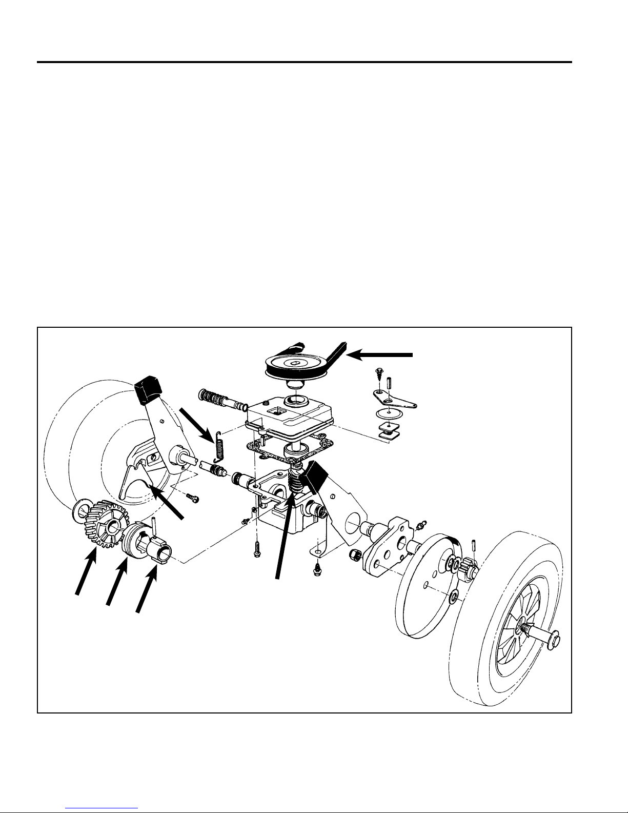
WORM DRIVE TRANSMISSION
GENERAL
There are two versions of the worm drive transmission.
The fi rst is a clutch type and is used on 21” front wheel
drive mowers. The second version is constant mesh and
is used on International 48cm rear wheel drive mowers.
INTERNALLY CLUTCHED
Description
This is a worm and helical gear transmission. The worm
shaft (input shaft) is driven by a belt from the engine
crankshaft. A spring which hooks into the tab on the
front of the transmission (where the roll pin is) and to
the mower housing, pivots the transmission forward to
maintain tension on the belt.
The worm is in constant mesh with the helical gear. The
clutching action is provided by a sliding clutch jaw. A shift
fork moves the clutch jaw to engage and disengage the
transmission. When the clutch jaw engages the helical
gear, power is transferred from the clutch jaw to the
sleeve inside the clutch jaw. The sleeve is pinned to the
axle. The axle then begins to rotate (Fig. 001).
A. Belt E. Shift Fork
B. Spring F. Sleeve
C. Helical Gear G. Input Shaft
D. Clutch Jaw (worm shaft)
A
C
B
E
G
D
F
1-2 WPM Drive Systems Manual
Fig 001 fi g 1
Page 21
WORM DRIVE TRANSMISSION
Lubrication
This transmission requires 90 wt. gear oil. A variable
weight such as 85w90 is acceptable as long as the
range includes 90 weight. The second part of the
requirement is an EP rating of GL 5 or higher.
The transmission has a fi ll/check plug in the front. With
the transmission level, fi ll until level with the hole. NOTE:
This is equal to about the center of the axle.
Unless the case is cracked, oil can not leak out. Even if
a seal fails, oil will leak out only to the bottom of the seal
on the axle.
If gear failure occurs, the resulting friction can cook the
oil down to a smear in the bottom of the case. This does
not indicate a lack of lubrication.
This type of transmission will last less than 30 minutes
with no lubrication. If a transmission lasts even a few
weeks in consumer use, it had lubrication to start.
The Shifting Process
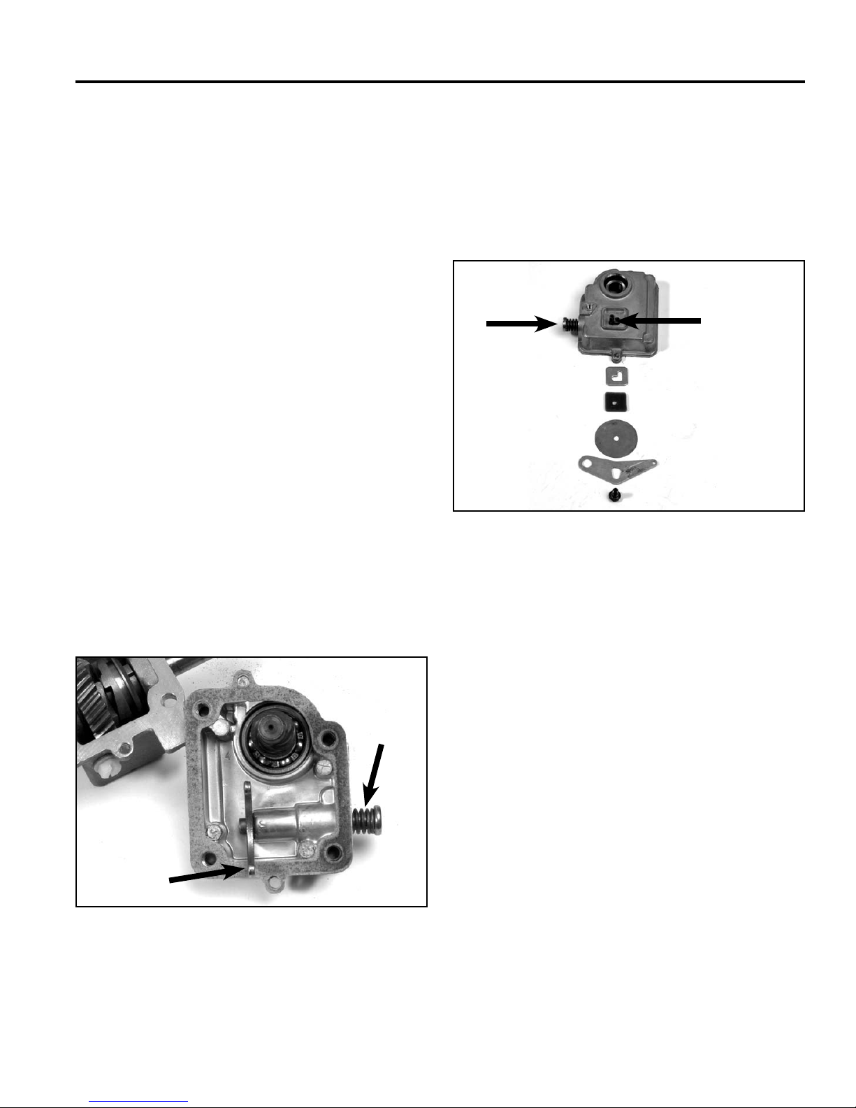
The upper end of the clutch fork slides over a groove in
a spring loaded rod. This spring pushes the shift fork and
clutch jaw towards the engaged position (Fig. 002).
The shift rod has a roll pin protruding through the top
of the transmission. This pin goes through a latch plate
with an L shaped slot in it. The slot guides the pin in its
travel from engagement to disengagement. Above the
latch plate is a dust fi lter and a dust cover. The shift arm
on top of the transmission holds all these parts in place
(Fig. 003).
G
A
B
C
D
E
F
Fig 003 3428-0165
A. Roll Pin E. Shift Arm
B. Latch Plate F. Screw
C. Dust Filter G. Shift Rod
D. Dust Cover
A
B
Fig 002 3428-0150
A. Shift Rod B. Shift Fork
When the shift arm is pulled to the rear by the shift
cable, the pin moves to the left side of the mower, then
to the rear. This moves the shift pin, the shift fork, and
the clutch jaw to the disengage position.
NOTE: Dirt packed in the latch plate can prevent
disengagement. The dust fi lter and dust
cover help prevent this failure.
When the shift cable is engaged, tension on the shift
arm is released. The spring on the shift rod applies
pressure to the rod, fork, and clutch jaw to engage the
transmission.
1-3WPM Drive Systems Manual
Page 22
WORM DRIVE TRANSMISSION
C
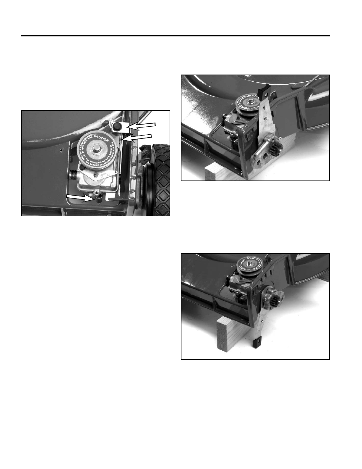
Removal & Installation (front wheel drive
applications)
1. Remove the belt cover and unhook the spring on
the front of the transmission. Slip the belt off the
transmission pulley (Fig. 004).
A
B
C
Fig 004 3428-0127
A. Cable Clamp C. Spring
B. Shift Cable
4. Remove both front wheels and wheel covers (Fig.
005).
Fig 005 3428-0129
5. Pivot (both) front spring arms forward until they
point straight down. (This removes the tension from
the pivot arms so the roll pin can be removed) (Fig.
006).
2. Raise the front of the mower off the bench and
support it with blocks.
3. Disconnect the shift cable.
Fig 006 3428-0131
1-4 WPM Drive Systems Manual
Page 23
WORM DRIVE TRANSMISSION
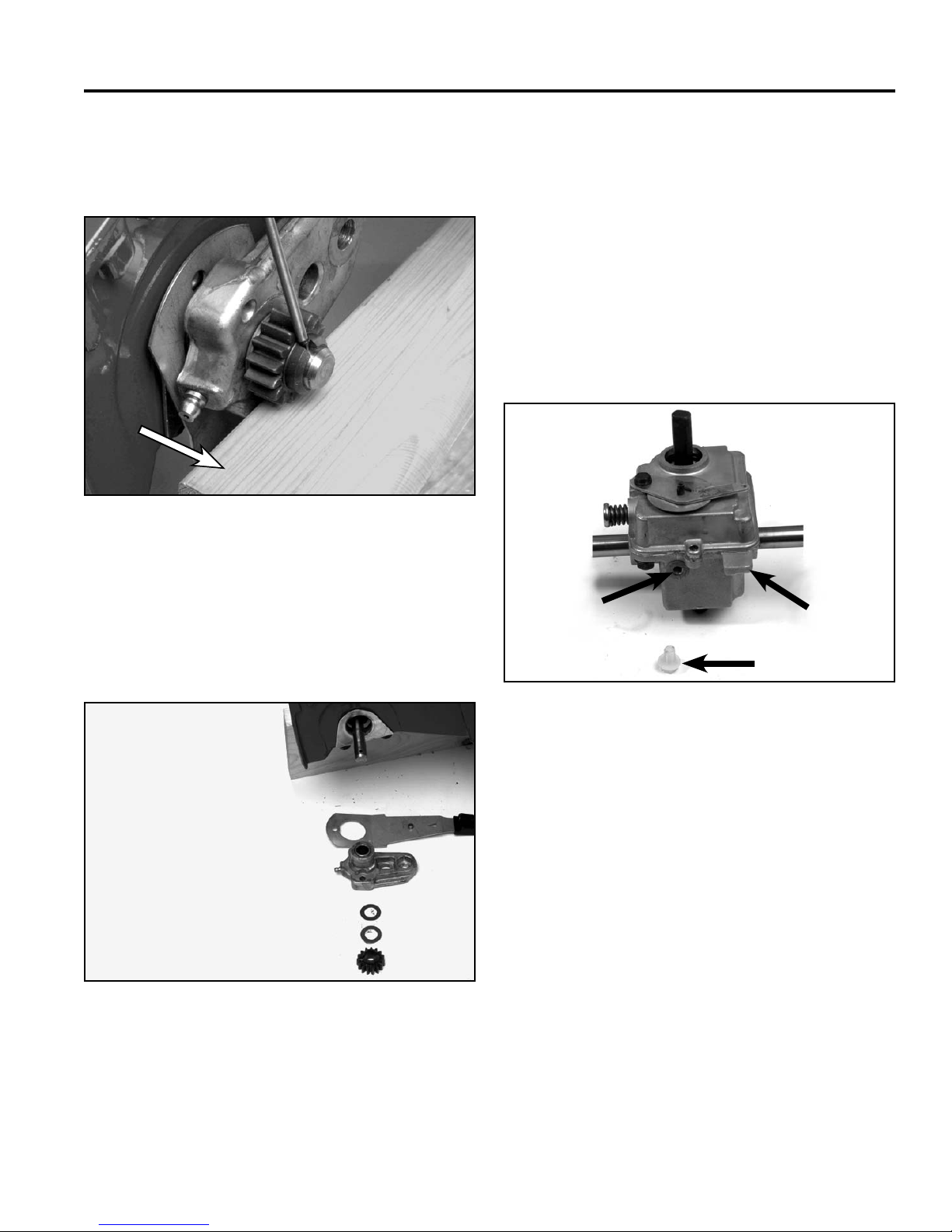
A
6. Place a block of wood under the wheel pinion for
support and drive the roll pin out of the axle (Fig.
007). Repeat the process on the other side.
A
Fig 007 3428-0135
A. Wood Block
8. Remove the transmission from the chassis.
9. Reverse the procedure to install.
NOTE: Support the wheel pinions with the wood
block while driving the roll pins in. This will
prevent the axle from being bent. Fill the
transmission with oil after it is installed in
the mower (Fig. 009).
Note the front of the transmission is identifi ed by the oil
fi ll/check screw and the fl at tab which is part of the lower
case.
7. The wheel pinion, thrust washer, pivot, and spring
arm will now slide off the end of the axle (Fig. 008).
Repeat the process on the other side.
Fig 008 3428-0137
A
C
B
Fig 009 3428-0166
A. Fill/Check C. Tab
B. Plug
Disassembly
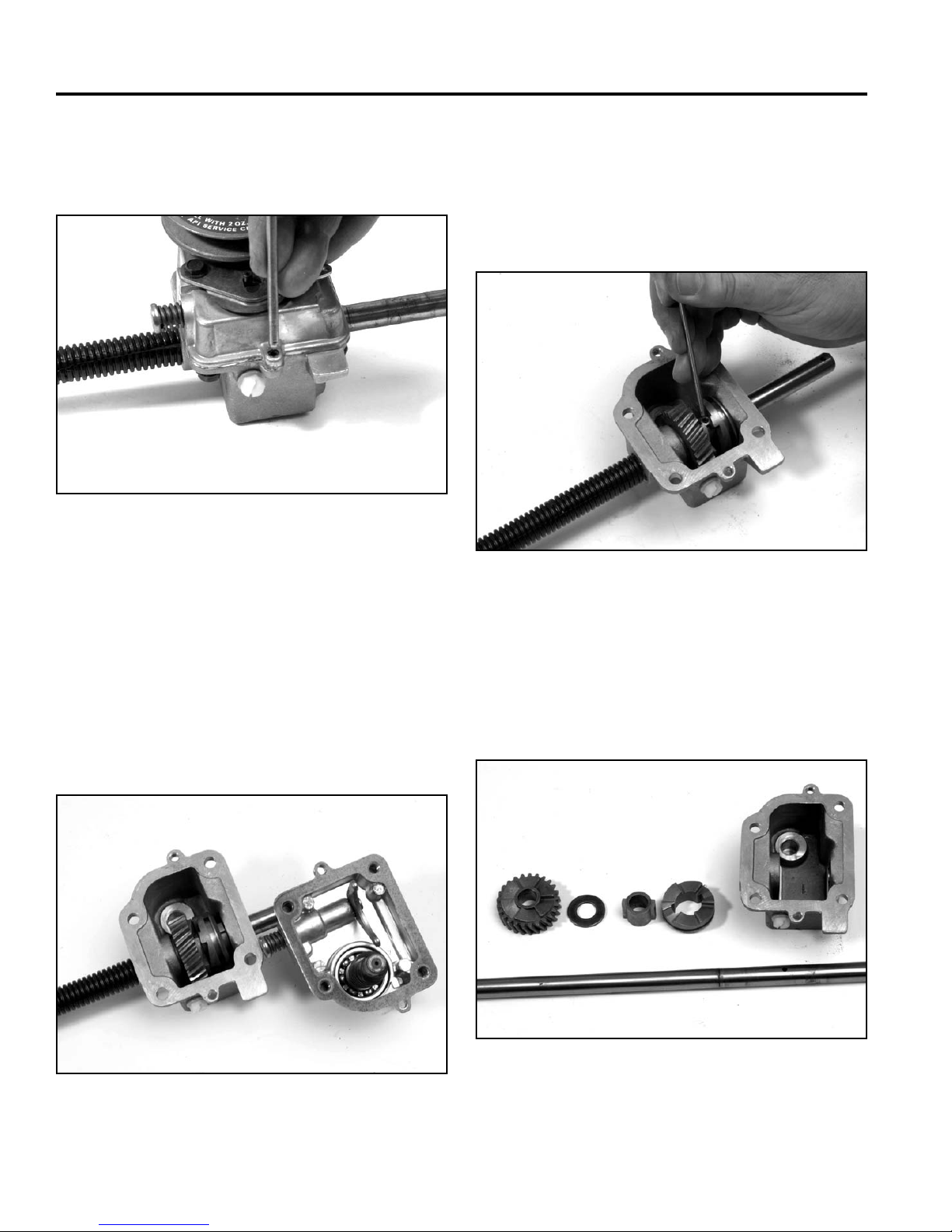
1. Cut and discard the push-on retainer on top of the
transmission pulley. Remove the belt and pulley.
1-5WPM Drive Systems Manual
Page 24
WORM DRIVE TRANSMISSION
2. Drive the roll pins out of the fl anges in the front
and rear of the case. (These pins align the top and
bottom parts of the case) (Fig. 010).
Fig 010 3428-0146
3. Remove the 4 self-tapping screw that connect the
top and bottom cases.
5. Push the worm shaft out of the cover. This may
require a little pressure.
6. To remove the axle, slide the clutch jaw to the side
and drive the roll pin out of the sleeve and axle (Fig.
012).
Fig 012 3428-0151
Note: If you turn this transmission on its side or
upside down, oil may leak out of the top. This
is not a sealed case.
4. Remove the transmission cover. The shift fork may
come with the cover or may fall into the bottom of
the case (Fig. 011).
Fig 011 3428-0148
7. If the axle bearings are to be re-used, clean the end
of the axle before drawing it out of the case.
8. Remove the sleeve, clutch jaw, helical gear, and
thrust washer (Fig. 013)
A
BC
D
Fig 013 3428-0153
A. Helical Gear C. Sleeve
B. Thrust Washer D. Clutch Jaw
1-6 WPM Drive Systems Manual
Page 25
WORM DRIVE TRANSMISSION
9. Clean the old gasket material from the mating
surfaces of the case and cover.
10. A hook or small screwdriver can be used to pry the
seals out of the case.
11. An arbor press or large vise will be needed when
removing and replacing the bushings.
12. Clean the oil residue and any metal shavings from
the case.
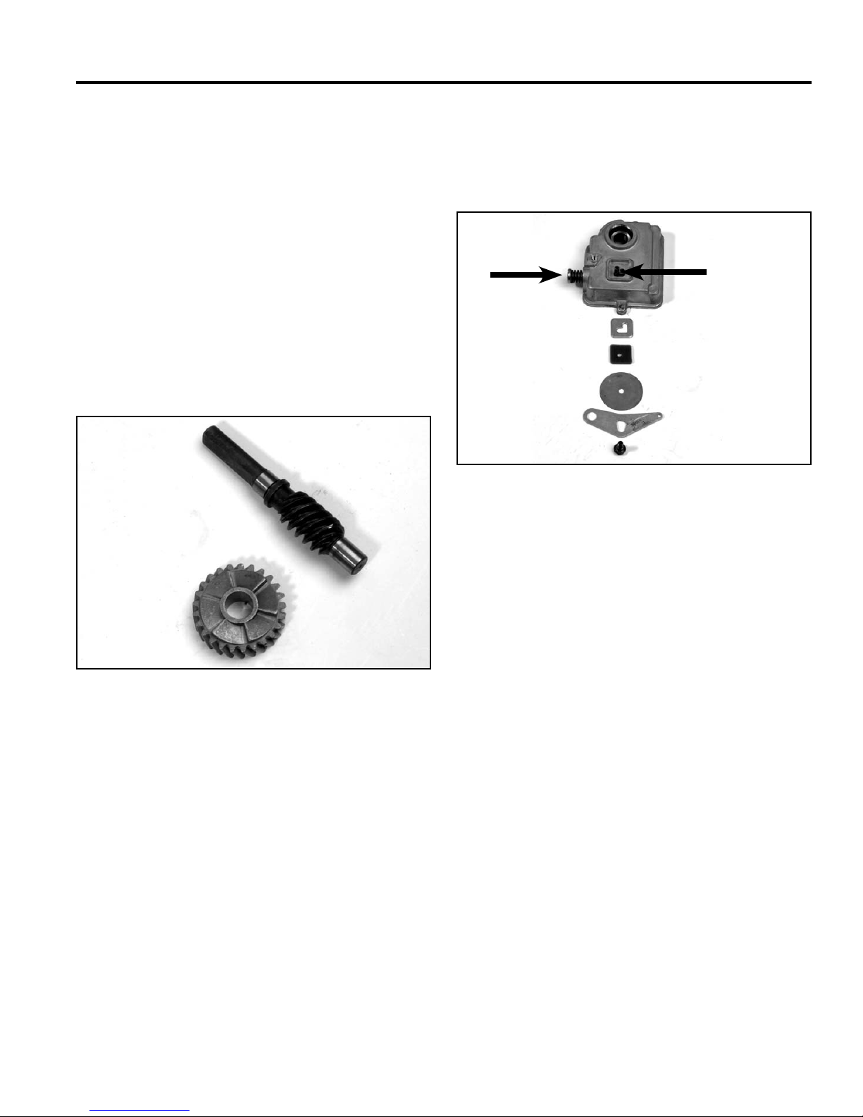
13. Worm and helical gears are sold as a set. Even after
a short run time, they will develop a wear pattern.
Replacing only one gear will result in rapid failure
(Fig. 014).
A
14. Remove the screw from the shift arm and remove
the shift arm, dust cover, and wear plate (Fig. 015). If
the ball bearing is to be replaced, press it out at this
time.
G
A
B
C
D
E
F
Fig 015 3428-0165
A. Roll Pin E. Shift Arm
B. Latch Plate F. Screw
C. Dust Filter G. Shift Rod
D. Dust Cover
B
A. Worm Shaft B. Helical Gear
Fig 014 3428-0157
15. Remove the roll pin and pull shifter rod out of the
cover. Clean the cover.
Assembly
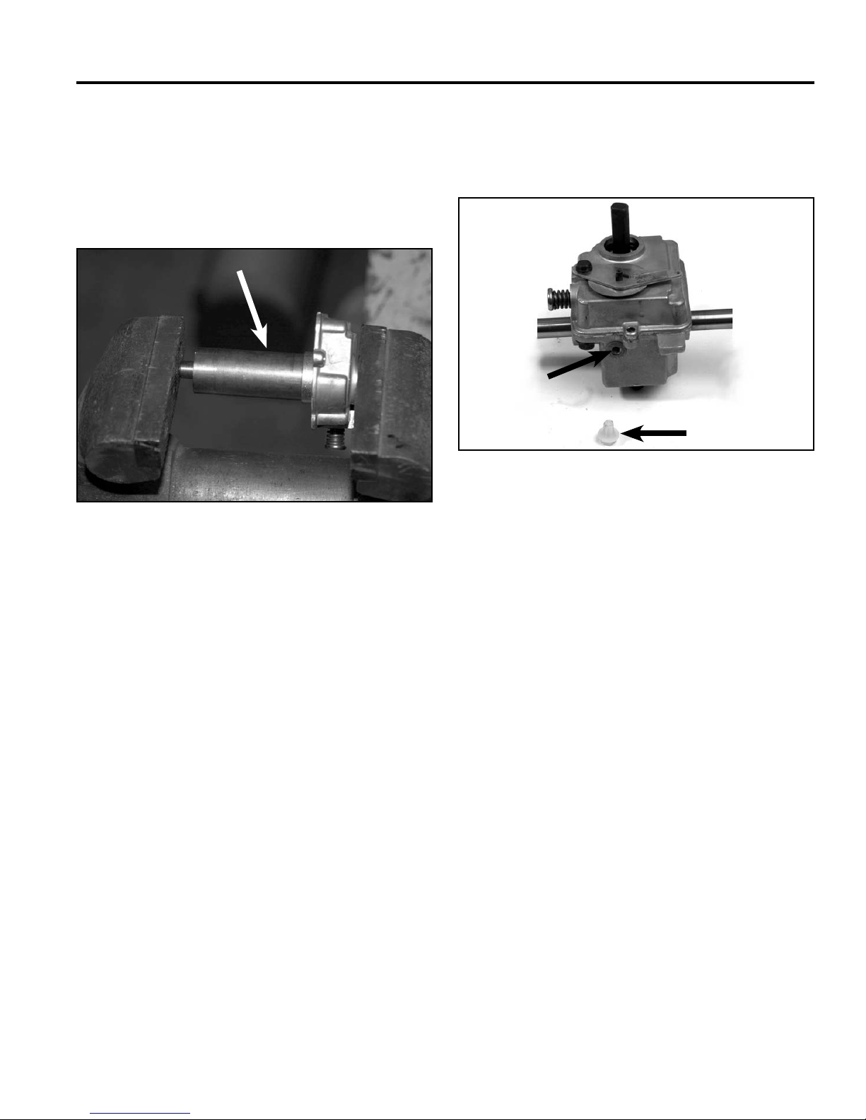
1. Use bushing installation tool P/N 27-0460, to press
in new axle bushings. This tool helps keep the
bushing straight and keeps the inner diameter of the
bushing correctly sized.
1-7WPM Drive Systems Manual
Page 26

WORM DRIVE TRANSMISSION
Note: The bushings are two different lengths. The
side of the case with the thicker boss uses
a longer busing to support the axle. The
bushings should be fl ush with the inside of
the case (Fig. 016).
A
Fig 016 3428-0158
A. Tool P/N 27-0460
3. Note: Some replacement axles have more than one
hole that can be used to pin the sleeve to the axle.
Refer to the original axle to identify the correct hole
to use. Then drive a roll pin through the sleeve and
axle (Fig. 017).
Fig 017 3428-0151
2. Clean the rust and dirt from the both ends of the
axle. Wipe the inner diameter of the bushings with
a clean cloth. Lightly oil the axle and insert it into
the gearcase. When facing the front of the gearbox,
insert the short end of the axle from left to right.
Install the thrust washer, helical gear, and the sleeve
and clutch jaw. Then push the axle through the other
side of the case.
4. Using a seal protector, slide new seals down each
side of the axle, Install the seal with the lip facing the
transmission. The outer edge of the seal should be
fl ush with the outside of the case. If a seal protector
is not available, wrap a piece of cellophane around
the axle (Fig. 018).
A
B
Fig 018 3428-0170
1-8 WPM Drive Systems Manual
A. Seal protector or B. Seal
Cellophane
Page 27
WORM DRIVE TRANSMISSION
5. If the bearing in the cover is being replaced, use tool
P/N 27-0490 to press it in place. This bearing only
has one seal. Install the bearing such that the seal
is visible from the top of the cover and the open side
faces the gears. Press the bearing in until it is fully
seated in the case (Fig. 019).
A
Fig 019 3428-0159
9. Fill the transmission with gear oil AFTER it is
installed in the mower. The top of this transmission is
not sealed. It will leak if tipped on its side (Fig. 020).
A
B
Fig 020 3428-0166
A. Fill/Check B. Plug
A. Tool P/N 27-0490
6. Install worm shaft in bearing.
7. Use a new gasket. Install the cover on the bottom
case and start the 4 self-tapping screws. Do not fully
tighten them.
8. Install the front and rear roll pins to align the cover
and case. Then secure the 4 self-tapping screws.
Controls
There are two control cables used with this system. One
cable operates the engine kill switch and fl ywheel brake;
the other controls the transmission.
1-9WPM Drive Systems Manual
Page 28
WORM DRIVE TRANSMISSION
Adjustment
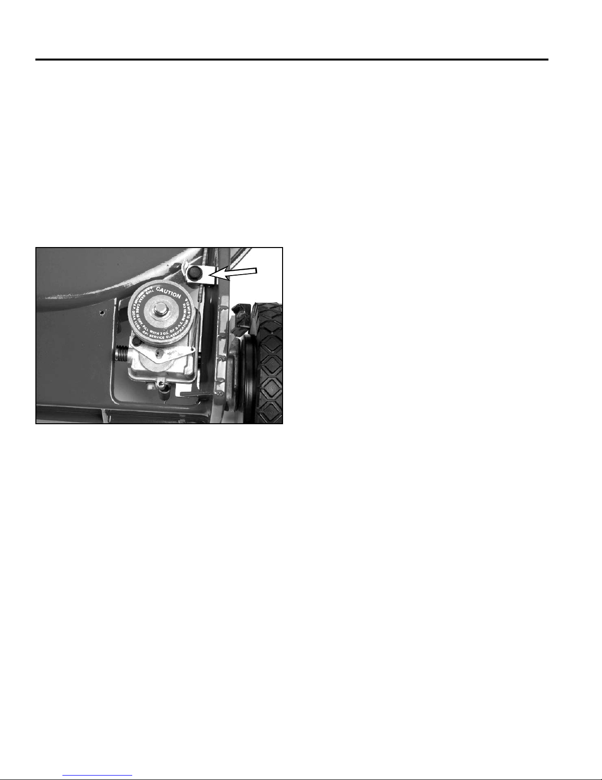
The transmission cable is a standard lever type. Since
the spring and pin on top of the transmission pushes the
shift fork towards the engaged position, the cable pulls
the shift arm to the rear to disengage the transmission.
The adjustment point is on the mower housing just to
the rear of the transmission. To adjust, pull the control to
the rear (disengage). Go to the cable clamp/adjustment.
Loosen the clamp, pull the cable to the rear until the shift
lever is as far back as it will go. Hold it there and tighten
the clamp (Fig. 021).
A
Fig 021 3428-0127
A. Cable Clamp
1-10 WPM Drive Systems Manual
Page 29
WORM DRIVE TRANSMISSION
CONSTANT MESH
Description
This transmission is very similar to the “INTERNALLY
CLUTCHED” on page 1 – 1. However, the helical gear
is different as there is no internal clutching (Fig. 022).
Engagement and disengagement is accomplished by
pivoting the transmission to tighten or loosen the belt.
Internal repair procedures are the same, as is the
lubrication requirement, 90 wt. gear oil rated GL-5 or
higher.
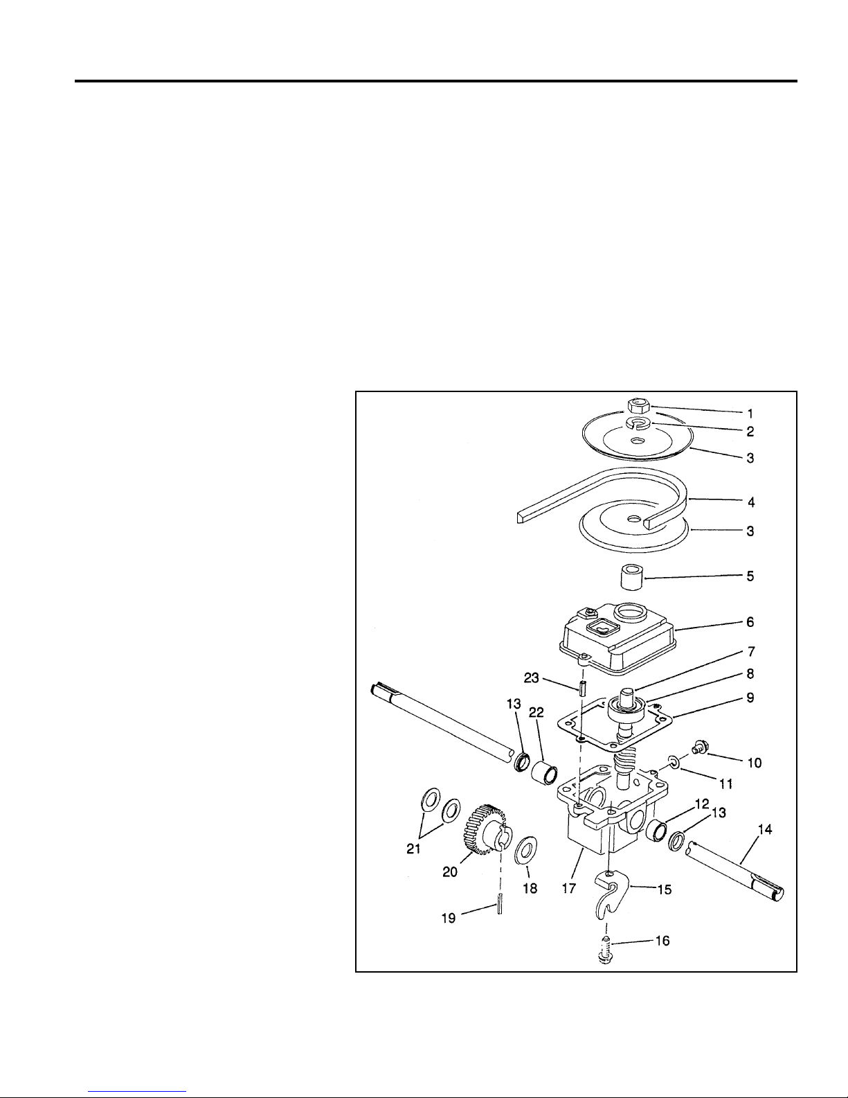
1. Jam nut 13. Oil Seal
2. Lock washer 14. Output shaft
3. Half pulley 15. Traction bracket
4. V Belt 16. Thread forming screw
5. Pulley spacer 17. Gearbox case
6. Gearbox cover 18. Thrust washer
7. Shaft & worm 19. Roll pin
8. Ball bearing 20. Helical gear
9. Gearbox gasket 21. Thrust washer
10. Check plug 22. Bushing
11. Gasket check plug 23. Roll pin
12. Bushing
The constant mesh type transmission is used in a 48cm
rear wheel drive application.
Fig 022 fi g 18-A
1-11WPM Drive Systems Manual
Page 30
WORM DRIVE TRANSMISSION
Removal and Installation
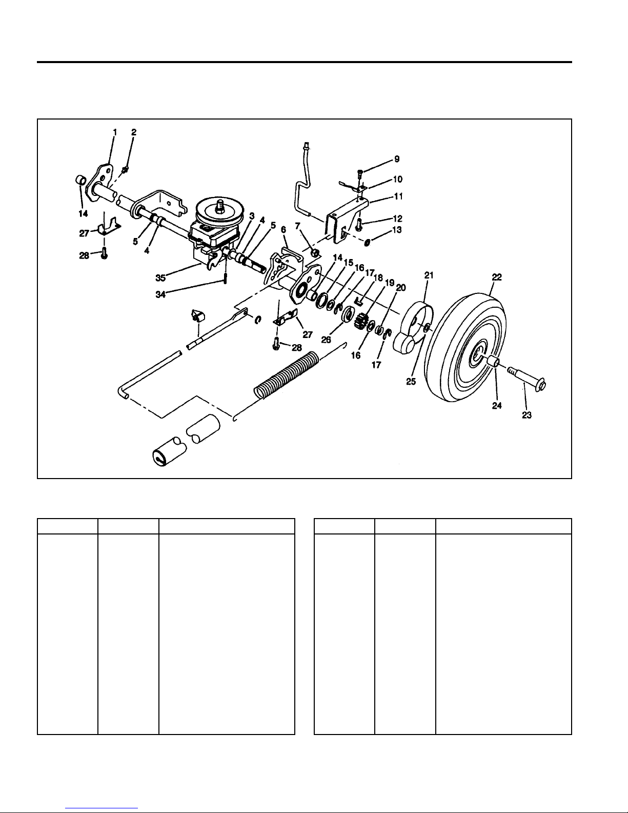
Fig 023 20911B sprearaxleassy
Ref. No. Qty Description
1
2
3
4
5
6
7
9
10
11
12
13
14
15
1-12 WPM Drive Systems Manual
1
2
2
2
2
1
2
1
2
1
2
1
2
2
Rear Pivot Assembly RH
(incl. Ref. #2, 4, 5 & 14)
Grease Fitting
Washer
Sleeve Bushing
Grease Seal
Rear Pivot Assembly LH
(incl. Ref. #3, 4, 5 & 14)
Locknut
Thread Forming Screw
Trigger Return Spring
H.O.C. Saddle
Thread Forming Screw
Push Nut
Needle Bearing
Friction Washer
Ref. No. Qty Description
16
17
18
19
20
21
22
23
24
25
26
27
28
34
35
4
4
1
2
2
2
2
2
4
2
2
2
4
2
1
Keyed Thrust Washer
Retaining Ring
LH Rocking Key
Pinion Gear
Compression Spring
Wheel Cover
Tire & Gear Assy Wheel
(incl. Ref. #24)
Wheel Bolt
Wheel Bushing
Wheel Spacer
Clutch Washer
Rear Suspension Plate
Thread Forming Screw
Roll Pin
Gearbox Assembly
Page 31
WORM DRIVE TRANSMISSION
To remove the transmission from the mower proceed as
follows:
1. Remove both rear wheels.
2. Remove the retaining rings, springs, gears, keys,
clutches, and pivot arms on both sides (“Wheel
Pinion Clutch” on page 5-2).
3. Remove the belt.
4. There is a suspension bracket on each side that
secures the transmission and pivot arms to the
chassis. Each bracket has 2 screws. Once they are
removed, the transmission will drop out.
To install, reverse the above process.
Fill the transmission level with the fi ll plug opening after it
is installed in the chassis. The top of the transmission is
not sealed, so it may leak if fi lled and tipped.
Controls
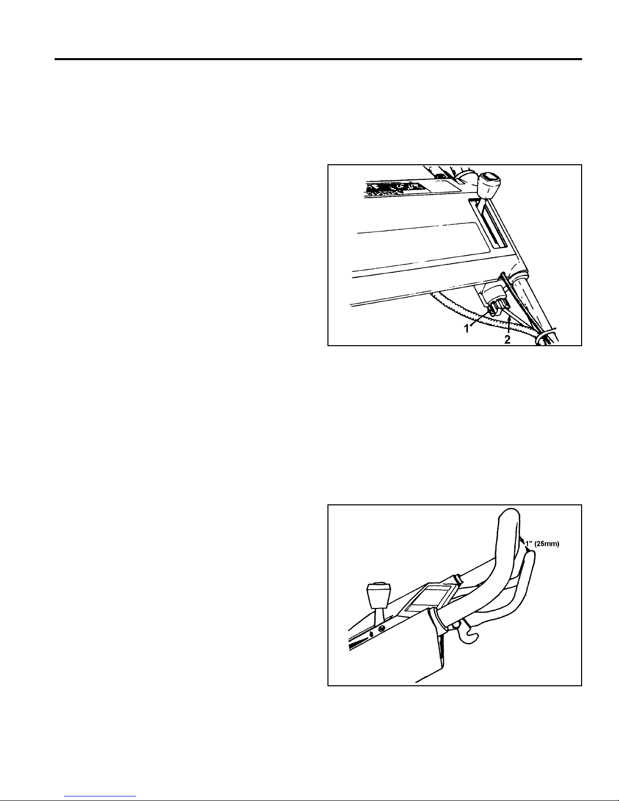
2. Rotate the adjustment knob under the lower lefthand side of the control panel ½ turn clockwise to
tighten the belt, or ½ turn counterclockwise to loosen
the belt. Hold the control cable while rotating the
knob to prevent the cable from turning (Fig. 024).
Fig 024 fi g 19
1. Knob 2. Cable
Adjusting Wheel Traction Drive
1. Stop the engine.
3. To check the adjustment, slowly squeeze the control
bar towards the handle. The cable is adjusted
correctly when resistance is felt when the control bar
is approximately 1” (25mm) from the upper handle
(Fig. 025).
Fig 025 fi g 20
1-13WPM Drive Systems Manual
Page 32

WORM DRIVE TRANSMISSION
4. If loss of traction or improper engagement still
occurs after adjustment, repeat steps 2 – 3 until
properly adjusted.
WHEEL CLUTCH
See Rocking Key Wheel Clutch, page 5-3.
1-14 WPM Drive Systems Manual
Page 33

SINGLE SPEED SPUR/BEVEL GEAR TRANSMISSION
Worm Drive Transmission . . . . . . . . . . . . . . . . . . . . . . . .
Single Speed Spur/Bevel Gear Transmission . . . . . . . . . . . . .
Single Speed Bevel Gear Transmission . . . . . . . . . . . . . . . .
Three Speed Transmission . . . . . . . . . . . . . . . . . . . . . . .
Wheel Pinion Clutch . . . . . . . . . . . . . . . . . . . . . . . . . . .
1
2
3
4
5
Blade Brake Clutch Systems (BBC), Blade Override
System (BOS), Blade Clutch Systems (BCS) . . . . . . . . . . . . .
Handles and Control Cables . . . . . . . . . . . . . . . . . . . . . .
Self-Propel Belt Replacement . . . . . . . . . . . . . . . . . . . . . .
6
7
8
2-1WPM Drive Systems Manual
Page 34
SINGLE SPEED SPUR/BEVEL GEAR TRANSMISSION
GEAR CASE ASSEMBLY
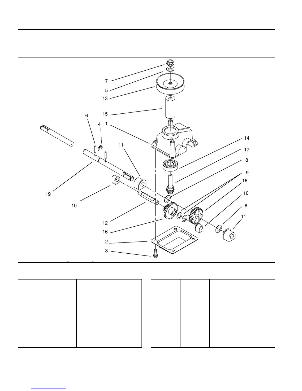
Ref. No. Qty Description
1
2
3
4
5
6
7
8
9
10
2-2 WPM Drive Systems Manual
1
1
1
1
2
2
2
2
1
1
Gear Case Casting
Gear Case Cover
HWH Screw
Retaining Ring
Flat Washer
Groove Pin
Lock Nut NI
Washer
Thrust Washer
Bushing
Fig 026 snglspspurbvlgearbox
Ref. No. Qty Description
11
12
13
14
15
16
17
18
19
2
1
1
2
2
2
2
2
2
Output Bushing
Intermediate Shaft
Pulley Half
Ball Bearing
Pulley Spacer
Bevel Gear 15t Spur, 37t
Pinion Gear Bevel
Gear
Output Shaft
Page 35
SINGLE SPEED SPUR/BEVEL GEAR TRANSMISSION
Description
This basic transmission has been in use for several
years. There are minor variations, such as different
shafts on the bevel pinion gear to accommodate belt
alignment on different chassies. All use a bevel pinion
input gear which mates with a combination bevel/spur
gear, which drives a fi nal spur gear.
Lubrication
Proper lubrication for this transmission is 2.5 – 3 fl uid
ounces (7.1cc – 9.0cc) of lithium based No. 2 grease.
Transmission Removal and Replacement
1. Raise the rear of the mower and support with a block
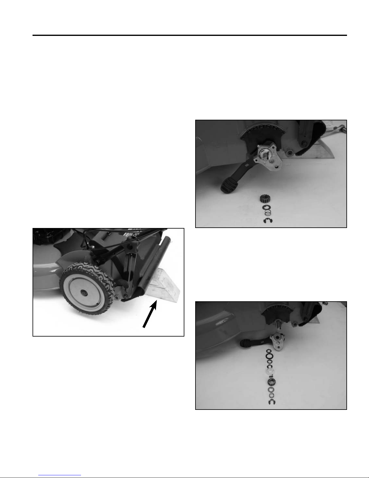
(Fig. 027).
2. Remove transmission belt cover.
3. Remove both rear wheels.
4. Remove retaining ring, spring, thrust washer, and
pinion from both axles (Fig. 028). Refer to “Wheel
Pinion Clutch” on page 5-3 for additional information
about the clutch mechanism.
A
Fig 027 PICT-1870
A. Wood block
Fig 028 PICT-1873a
5. Continue disassembly, remove rocking key, clutch
washer, klip ring, keyed thrust washer, pivot arm
thrust washer, and friction ring. The pivot arm and
spring arm will then slide off the axle (Fig. 029).
Fig 029 PICT-1874a
2-3WPM Drive Systems Manual
Page 36
SINGLE SPEED SPUR/BEVEL GEAR TRANSMISSION
A
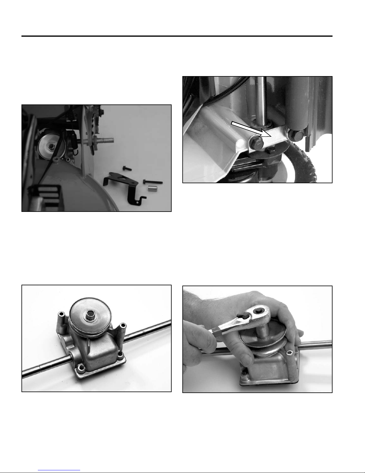
6. Remove the belt guide. Note the location of the
spacer under the front mounting screw (Fig. 030).
Do not try to force the belt off the pulley without
removing the belt guide. This often results in
damage to the belt or slightly bending the belt guide,
causing an increased tendency for belt jumping.
Fig 030 PICT-1880a
On some models, removing these 2 screws makes
transmission removal easier (Fig. 032).
A
Fig 032 3428-0121
A. End cap
7. The transmission can be moved to the right until
the short end of the axle clears the housing and
the transmission can be removed (Fig. 031). Some
models have the axle shaft retained by an end cap.
Fig 031 3128-0074
Transmission Internal Repair
The nut on the pulley can be removed now. The spacer
under the pulley varies with the chassis and the length
of the shaft on the pinion (Fig. 033). Remove the selftapping screws holding the cover on the transmission.
Fig 033 3428-0008
2-4 WPM Drive Systems Manual
Page 37
SINGLE SPEED SPUR/BEVEL GEAR TRANSMISSION
Before removing the parts from the case, note the
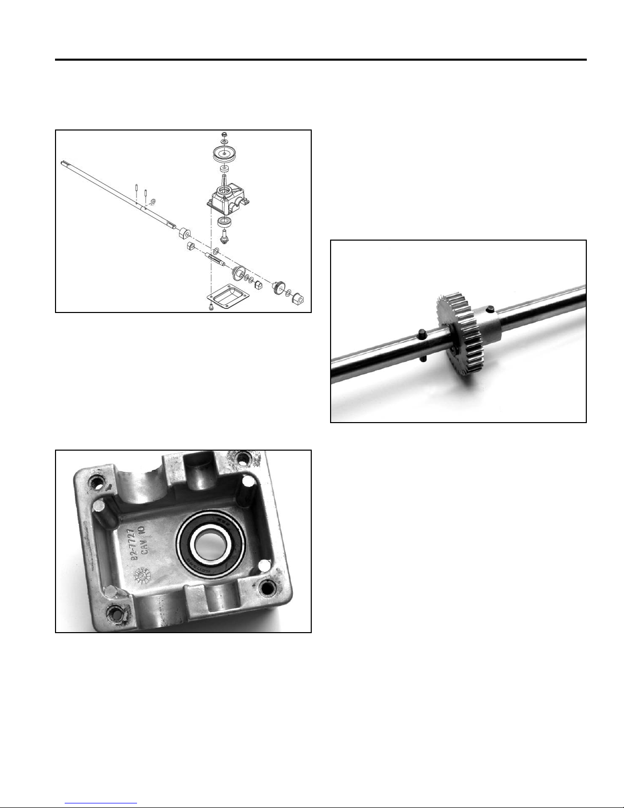
quantity and location of the thrust washers (Fig. 034).
Fig 034 108-8140-1b
Remove the axle and intermediate shaft with the gears.
The bearing in the cover should be sealed on both sides.
Inspect the bearing and its seals for damage (Fig. 035).
Replace as necessary. The bearing is pressed into the
cover. Make sure bearing is fully seated.
Clean the gears in solvent and inspect carefully. Any
damaged gear must be replaced. Also replace the mate
for the damaged gear. When gears run together, they
develop a wear pattern that will result in premature
failure if only one gear is replaced. The exception for this
is if the transmission has VERY little running time before
failure.
The axle has two roll pins through it. One connects the
single spur gear to the axle (Fig. 036). The other pin
aligns the axle and transmission case.
Fig 036 3428-0016
Fig 035 3428-0018
Assembly
Assemble with the correct number of thrust washers.
Refer to the parts manual if there is any doubt at all. It
is not possible to locate the shafts and bearings in the
wrong location, due to differences in sizes.
2-5WPM Drive Systems Manual
Page 38
SINGLE SPEED SPUR/BEVEL GEAR TRANSMISSION
Prior to installation of oil impregnated bushings, it is
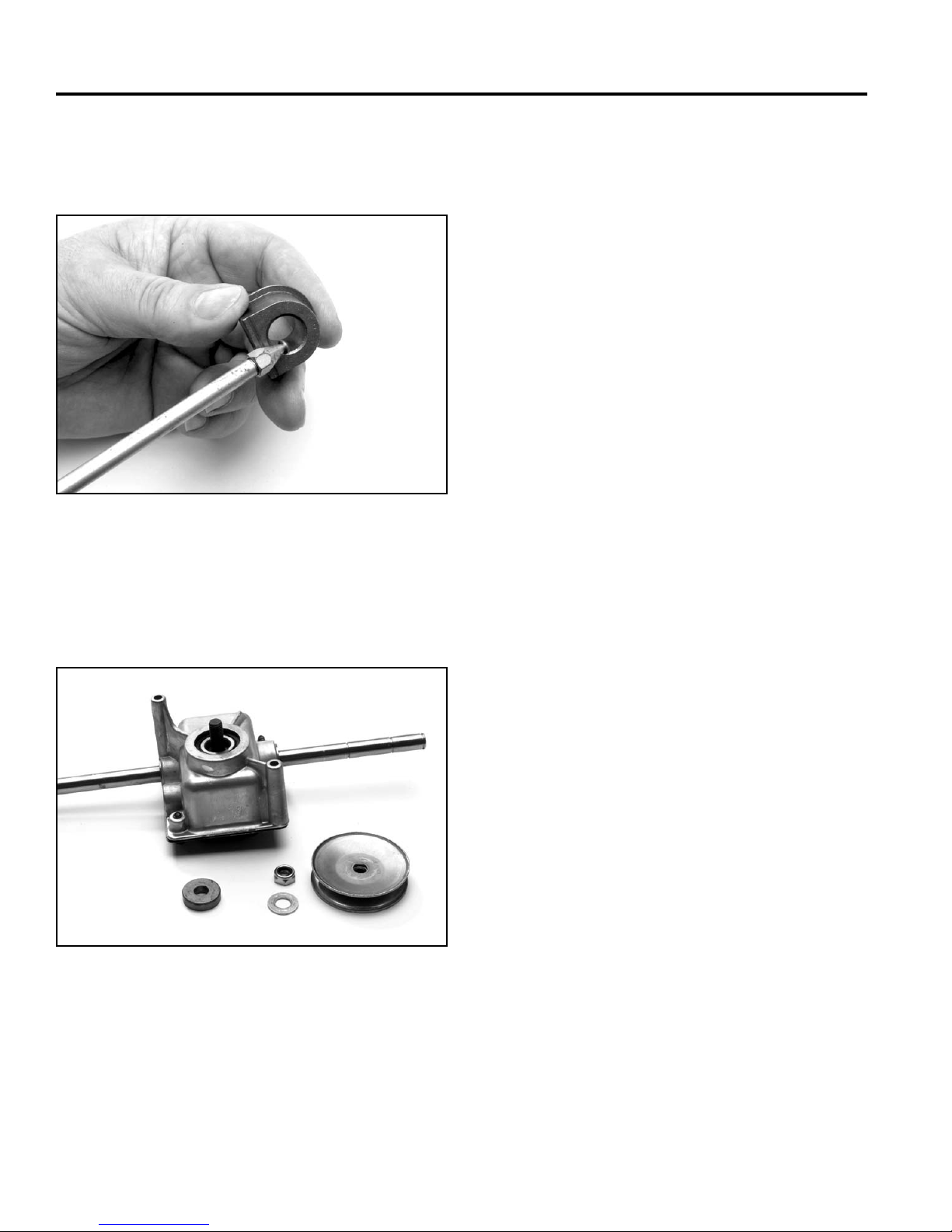
wise to apply a light coating of engine oil to the running
surface (Fig. 037). Add grease and install the cover.
Fig 037 3428-0019
Finally, install the spacer and pulley on the input shaft.
The internal gears will help hold the pinion while the nut
is tightened (Fig. 038).
Insert the transmission back into the chassis. Refer
to the section on the wheel pinion clutch for assembly
instructions.
Install self propel cable. Adjust as needed; see “Handles
and Control Cables” Section 7.
Fig 038 3428-0022
2-6 WPM Drive Systems Manual
Page 39

SINGLE SPEED BEVEL GEAR TRANSMISSION
Worm Drive Transmission . . . . . . . . . . . . . . . . . . . . . . . .
Single Speed Spur/Bevel Gear Transmission . . . . . . . . . . . . .
Single Speed Bevel Gear Transmission . . . . . . . . . . . . . . . .
Three Speed Transmission . . . . . . . . . . . . . . . . . . . . . . .
Wheel Pinion Clutch . . . . . . . . . . . . . . . . . . . . . . . . . . .
1
2
3
4
5
Blade Brake Clutch Systems (BBC), Blade Override
System (BOS), Blade Clutch Systems (BCS) . . . . . . . . . . . . .
Handles and Control Cables . . . . . . . . . . . . . . . . . . . . . .
Self-Propel Belt Replacement . . . . . . . . . . . . . . . . . . . . . .
6
7
8
3-1WPM Drive Systems Manual
Page 40
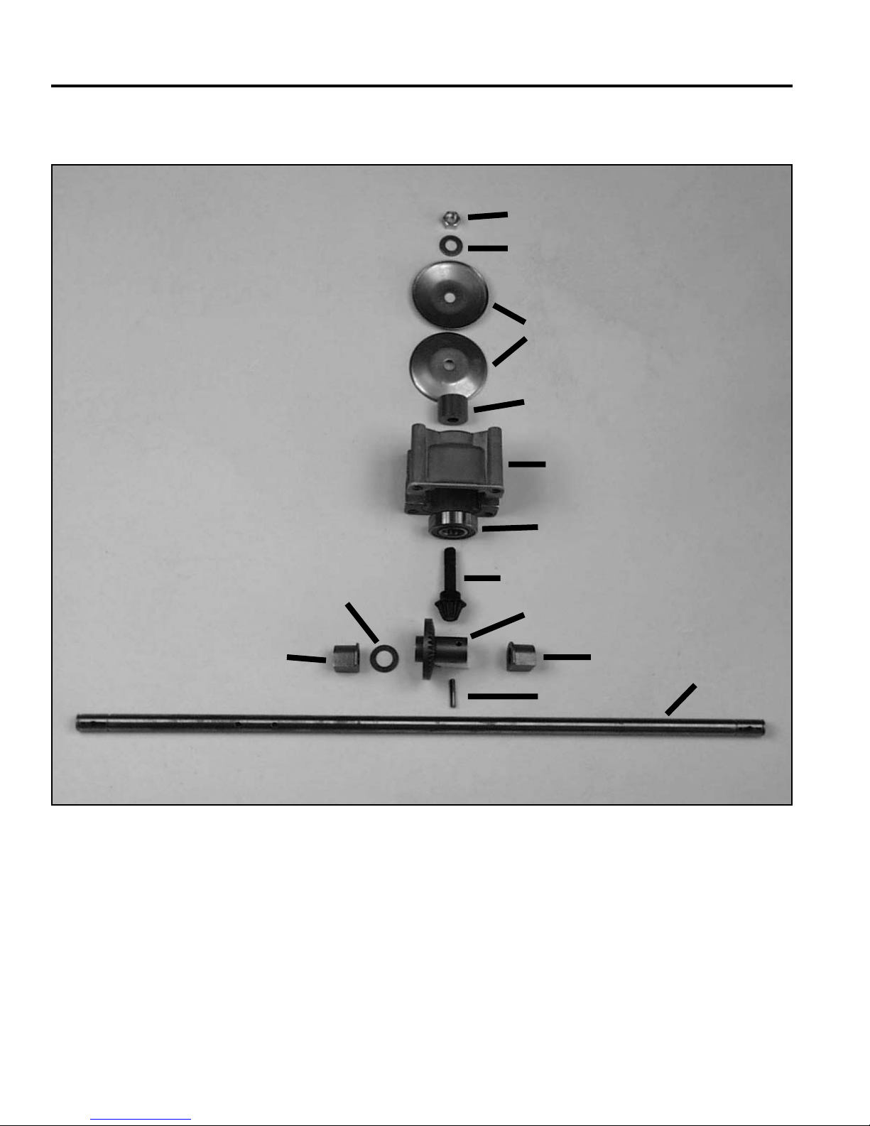
SINGLE SPEED BEVEL GEAR TRANSMISSION
EXPLODED VIEW - SINGLE SPEED BEVEL GEAR TRANSMISSION
A
B
C
D
E
G
I
J
H
Fig 039 single speedtrans a
A. Nut H. Bushing
B. Washer I. Thrust washer
C. Pulley J. Bevel Gear
D. Spacer K. Bushing
E. Housing L. Roll pin
F. Bearing M. Axle
G. Pinion
F
L
K
M
3-2 WPM Drive Systems Manual
Page 41
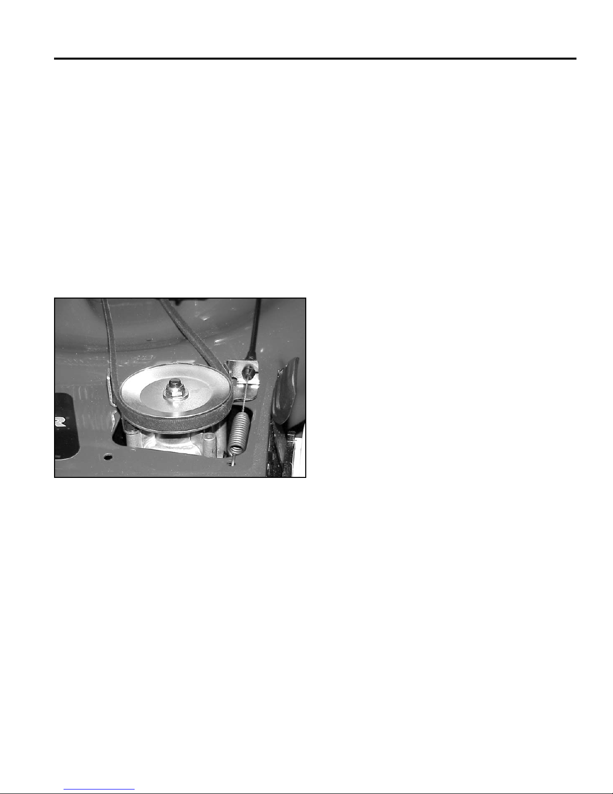
SINGLE SPEED BEVEL GEAR TRANSMISSION
GENERAL INFORMATION
This transmission was fi rst used on 22” steel deck
models for 2002. It is used in both front wheel and rear
wheel drive confi gurations. The bevel gear is reversed
when used in the front drive versus the rear drive to
change axle shaft direction of rotation.
In both cases, the gears are in constant mesh. Clutching
is done by rocking the transmission to tighten or loosen
the drive belt (Fig. 040). The control cable will move
the transmission to tighten the belt. When released, the
weight of the transmission causes it to rock towards the
engine to disengage.
Fig 040 MVC-485
3-3WPM Drive Systems Manual
Page 42
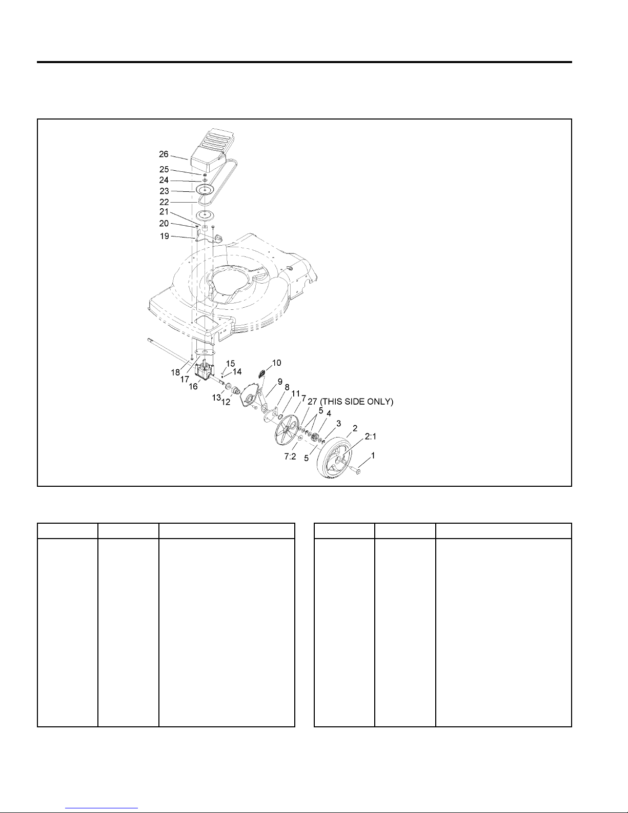
SINGLE SPEED BEVEL GEAR TRANSMISSION
FRONT AXLE AND TRANSMISSION ASSEMBLY
3354-613 Rev A
Fig 041 3354-613(5)
Ref. No. Qty Description
1
2
2:1
3
4
5
7
7:1
7:2
8
9
10
11
12
13
3-4 WPM Drive Systems Manual
2
2
2
4
2
6
2
1
1
2
2
2
2
2
2
Bolt-Shoulder
Wheel Gear ASM
Bushing
Klipring-Locking
Gear-Pinion, 13T
Washer-Thrust
Cover-Wheel
Cover
Washer-Stepped
Arm-Pivot, Front
Arm-Spring
Knob-Lever, HOC
Ring-Retaining
Retainer-Bearing, HOC
Bearing-Ball
Ref. No. Qty Description
14
15
16
17
18
19
20
21
22
23
24
25
26
27
2
2
1
1
2
1
2
1
1
2
1
1
1
1
Spring-Compression
Key
Transmission ASM
Gasket-Gearbox
Screw-HWH
Bracket-Pivot, Fwd
Screw-HWH
Spacer
V-Belt
Pulley-Half, Front
Washer-Flat
Nut-Lock
Cover-Belt, Front
Washer
Page 43
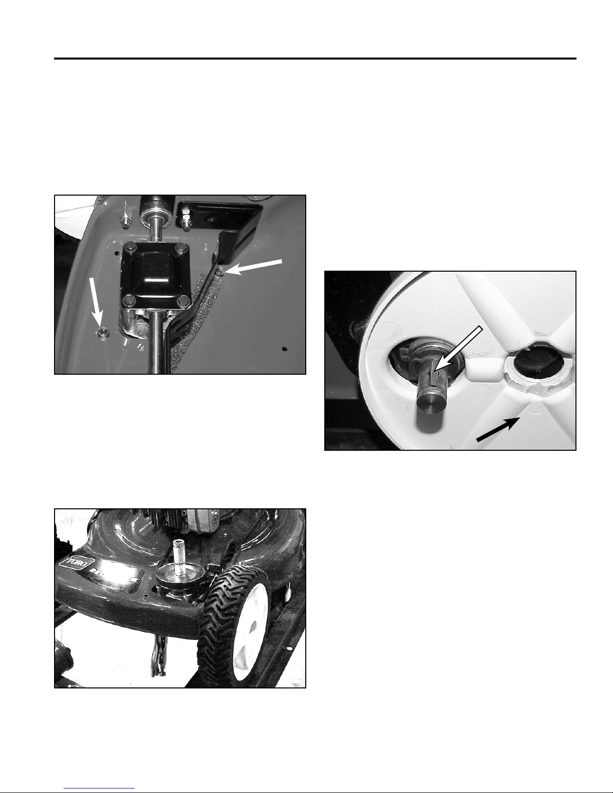
SINGLE SPEED BEVEL GEAR TRANSMISSION
A
22” FRONT WHEEL DRIVE MODELS
Remove Transmission
1. Block the front of the mower up. There are two
screws that secure the belt cover to the housing.
They are accessed from the bottom (Fig. 042).
4. Remove the nut, washer, transmission pulley halves,
and spacer.
5. Remove the belt guide.
6. Remove both front wheels; note there is a washer
between the wheel and wheel cover.
7. To remove the wheel pinions, remove the klip ring
and thrust washer. The pinion will now slide off the
axle (Fig. 044).
Note: The spring-loaded drive key is under the
pinion.
A
Fig 042 MVC-482
2. Slip the belt out between the transmission pulley and
belt guide.
3. Grip the axle with locking pliers and remove the
locknut on the transmission pulley (Fig. 043)
B
Fig 044 MVC-472
A. Key B. Wheel cover
8. Remove the wheel cover.
Fig 043 MVC-486
3-5WPM Drive Systems Manual
Page 44
SINGLE SPEED BEVEL GEAR TRANSMISSION
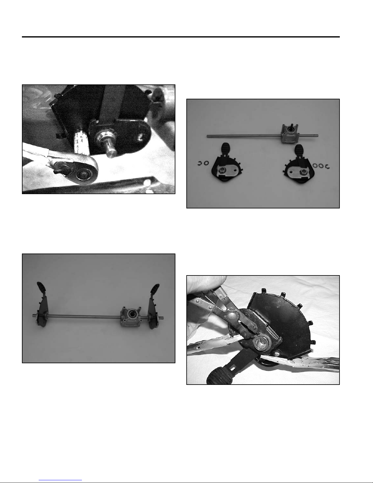
9. Remove the two bolts and nuts securing each pivot
arm to the housing. There is a notch in the pivot arm
for clearance of a socket (Fig. 045).
Fig 045 MVC-475
The axle assembly will now drop out of the chassis
(Fig. 046).
10. Remove the klip ring and thrust washer from each
end of the axle (the left side has 2 thrust washers,
the right side, one). The bearing, bearing retainer,
HOC plate, spring arm and pivot arm all come off as
one unit (Fig. 047).
Fig 047 PICT-1858a
11. To disassemble the pivot arm assembly, compress
the components with two clamps or locking pliers
(Fig. 048).
Fig 046 PICT-1857a
3-6 WPM Drive Systems Manual
Fig 048 MVC-478
Page 45
SINGLE SPEED BEVEL GEAR TRANSMISSION
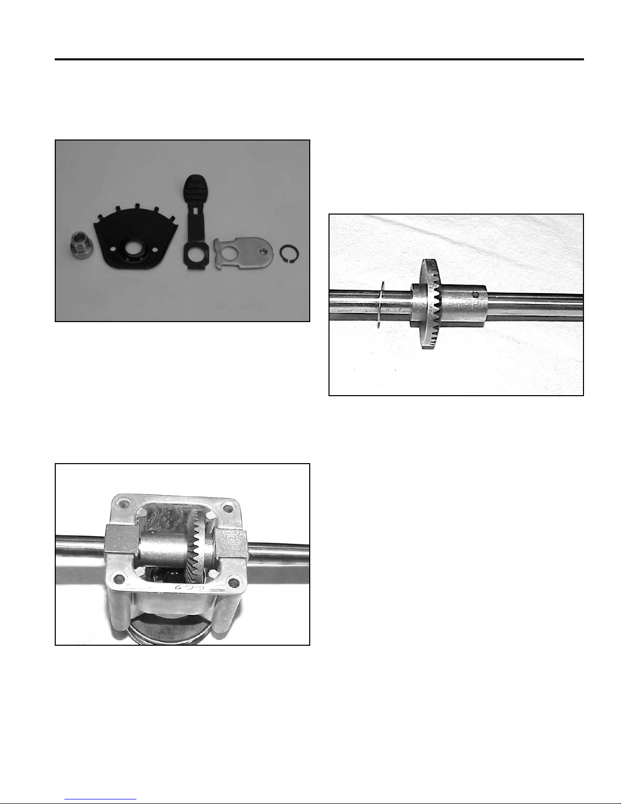
The snap ring can now be removed. Loosen the
clamps with care due to the spring arm tension.
Separate the spring arm components (Fig. 049).
Fig 049 PICT-1869a
2. Since the pulley was previously removed, the input
shaft will now slip out of the transmission case.
3. If the input bearing is to be removed, press it out of
the case now.
4. Slide the bearings and thrust washer off the axle.
Drive the roll pin out and the bevel gear can be
removed (Fig. 051).
Transmission Disassembly
1. Remove the 4 screws holding the cover onto the
transmission. The axle, bearings, and bevel gear
can be lifted out (Fig. 050).
Fig 050 MVC-462
Fig 051 MVC-468
Transmission Assembly
Assemble in reverse order.
See Assembly Tips next page.
3-7WPM Drive Systems Manual
Page 46
SINGLE SPEED BEVEL GEAR TRANSMISSION
Assembly Tips
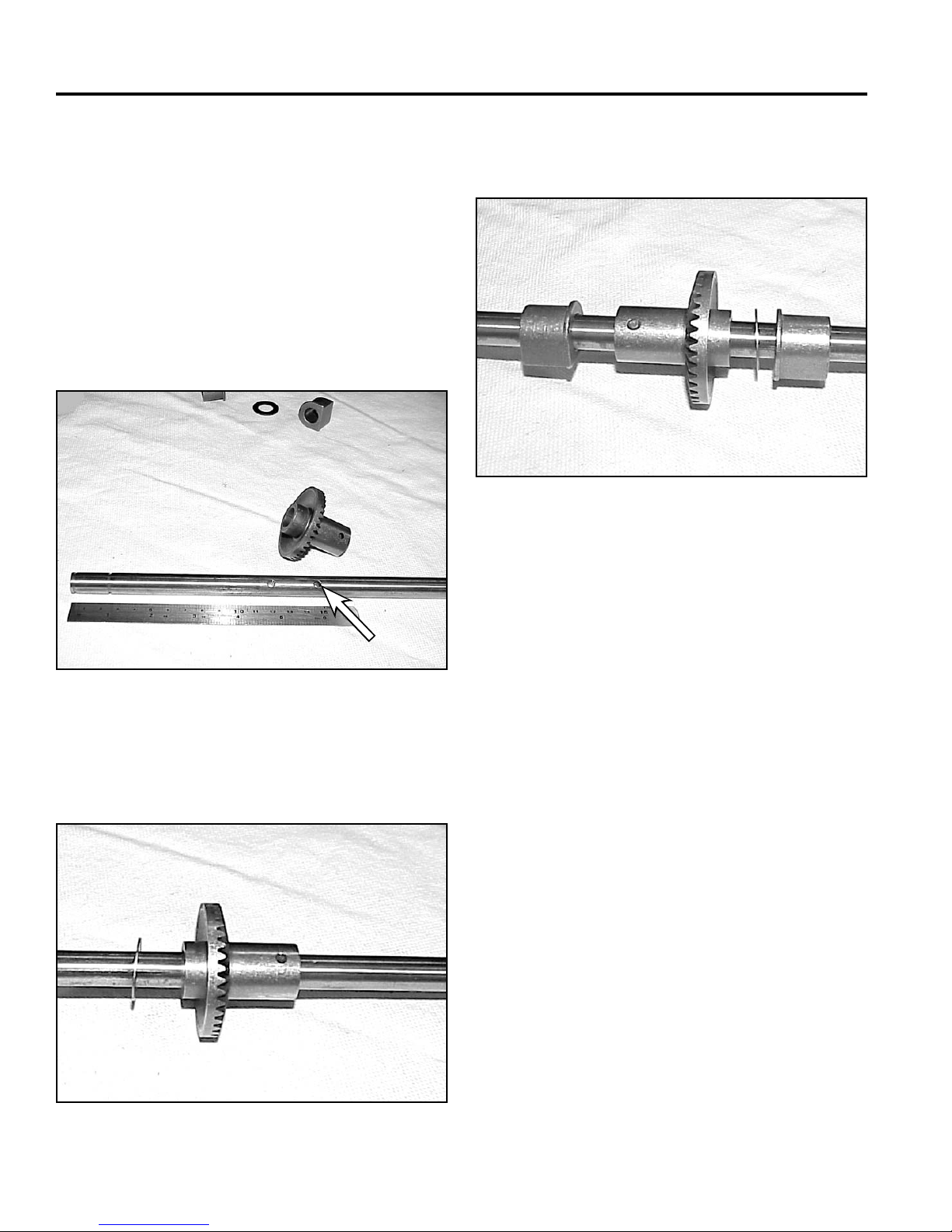
1. The same axle is used for both front and rear drive
versions. There are two holes in the axle about one
inch apart. Front wheel drive transmissions use the
hole in the axle that is about 5 ¾” (14.6cm) from the
end or closest to the center of the axle (Fig. 052).
Slip the gear on such that the teeth and longest hub
face the longer end of the axle. Drive the pin into
place. A double check is that neither of the pin holes
should be visible when the gear is installed.
3. Install the transmission bearings with the fl ange
facing the gear (Fig. 054).
Fig 054 MVC-470
4. If the input bearing was removed, press the new one
in until it bottoms in the case.
Fig 052 MVC-466
2. Install the trust washer on the side of the gear with
the shorter hub, away from the gear teeth (Fig. 053).
5. Fill the transmission case approximately 2/3 full with
#2 lithium base grease.
6. Assemble the bearing, bearing retainer, height of
cut plate, spring arm and pivot arm. Use two clamps
or vise grips to compress the assembly so the snap
ring can be installed.
Note: Install the snap ring with the sharp edge
facing away from the spring arm.
Fig 053 MVC-468
3-8 WPM Drive Systems Manual
Page 47
SINGLE SPEED BEVEL GEAR TRANSMISSION
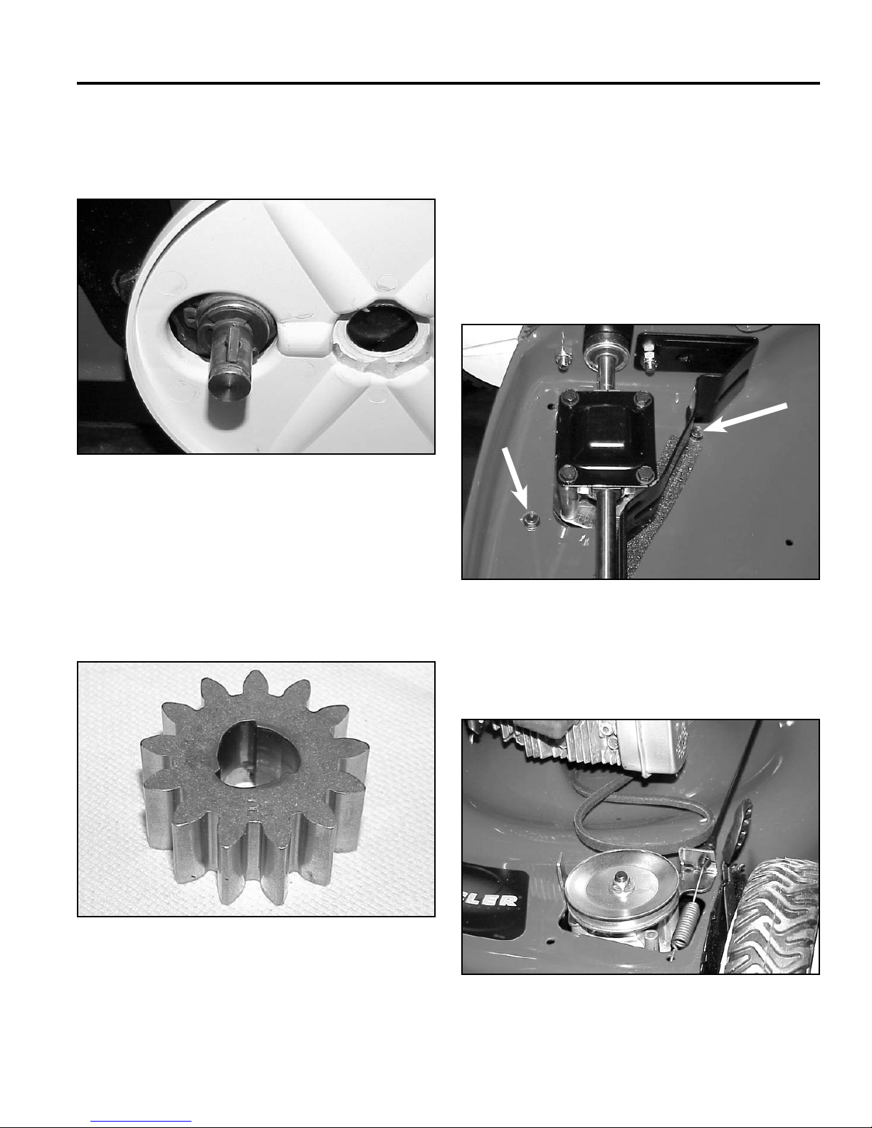
7. Coat the axle, key, and spring with #2 molybendum
disulfi de base grease or anti-seize compound before
installing the pinion (Fig. 055).
Fig 055 MVC-472
Belt Service - Front Wheel Drive Models
To replace the self-propelled drive belt, proceed as
follows:
1. Drain the fuel and oil and tip the mower on its right
side.
2. Remove the two screws securing the belt cover from
under the housing (Fig. 057).
8. The wheel pinion is marked with an R and L for right
and left. Identify right and left from the operator’s
position (Fig. 056). On the right side, the letter R
should face out. The letter L should face out on
the left side. If the wheel pinions are reversed, the
wheels will not drive.
R
Fig 056 MVC-474
Fig 057 MVC-482
3. Slip the belt off the transmission pulley and push it
towards the engine (Fig. 058).
Note: For more information on the wheel clutch see
Section 5, Wheel Pinion Clutch.
Fig 058 MVC-487
3-9WPM Drive Systems Manual
Page 48
SINGLE SPEED BEVEL GEAR TRANSMISSION
4. Remove one of the mounting screws for the belt
guide and loosen the other. DO NOT bend the belt
guide (Fig. 059).
Fig 059 MVC-490
Note: Blade removed for clarity. The blade can
be removed, but it is not required for belt
replacement.
22” TORO & LAWN-BOY REAR
WHEEL DRIVE MODELS
Transmission Removal and Belt
Replacement
On rear wheel drive models, it is necessary to separate
the rear drive assembly from the mower housing in order
to change the drive belt.
1. Drain fuel and oil from the engine.
2. Remove the single retaining screw from the center of
the bag door spring. Slide the door to one side and
remove it from the rear HOC side plates (Fig. 061).
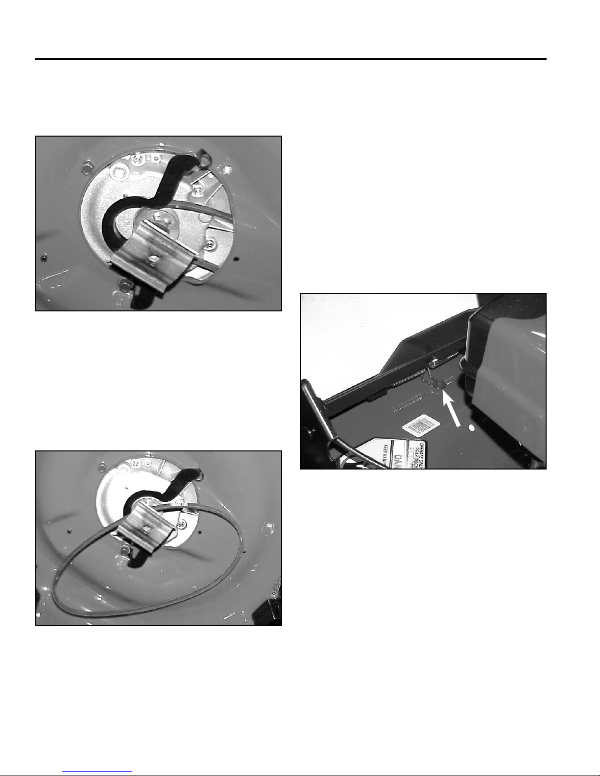
5. Slip the belt out of the crankshaft pulley and over the
blade (Fig. 060).
Fig 060 MVC-491
Fig 061 MVC-733
3-10 WPM Drive Systems Manual
Page 49
SINGLE SPEED BEVEL GEAR TRANSMISSION
A
B
A
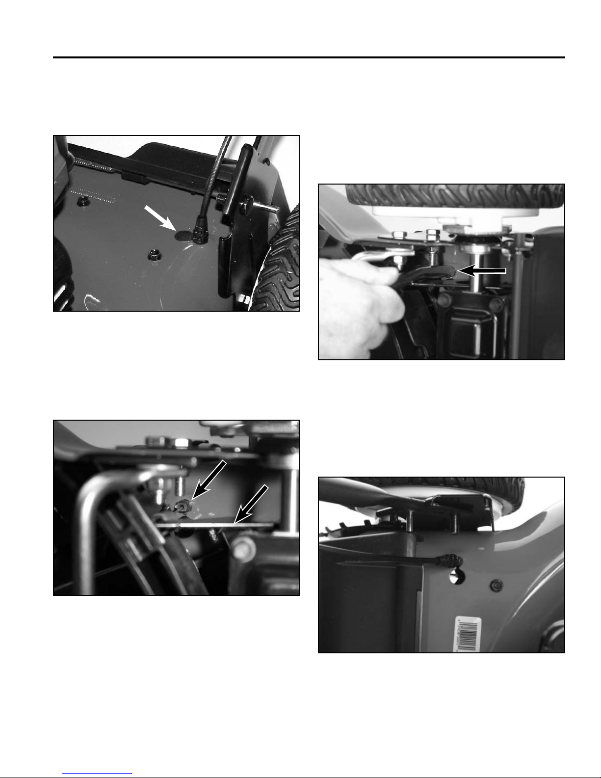
3. Remove the plug from the hole next to where the
self propel cable goes through the chassis (Fig.
062).
Fig 062 MVC-735
4. Tip the mower on its side. The cable snaps in from
the top and connects to an arm on the transmission
belt guide (Fig. 063).
5. The cable tool (P/N 105-6819) will compress the
locking tabs on the cable so it can be removed from
the housing.
6. Slide the cable tool over the end of the cable and
push (Fig. 064). At the same time, reach around the
mower and pull the cable out of the housing.
A
Fig 064 PICT-1895a
A. Cable tool
A
B
Fig 063 PICT-1884a
A. Cable B. Belt guide
7. With the plug removed from the larger hole next to
the cable, move the cable through the slot (Fig. 065).
Fig 065 PICT-1904
3-11WPM Drive Systems Manual
Page 50
SINGLE SPEED BEVEL GEAR TRANSMISSION
8. Push it into the larger hole (Fig. 066).
Fig 066 PICT-1897
9. Remove both rear wheels and both wheel covers.
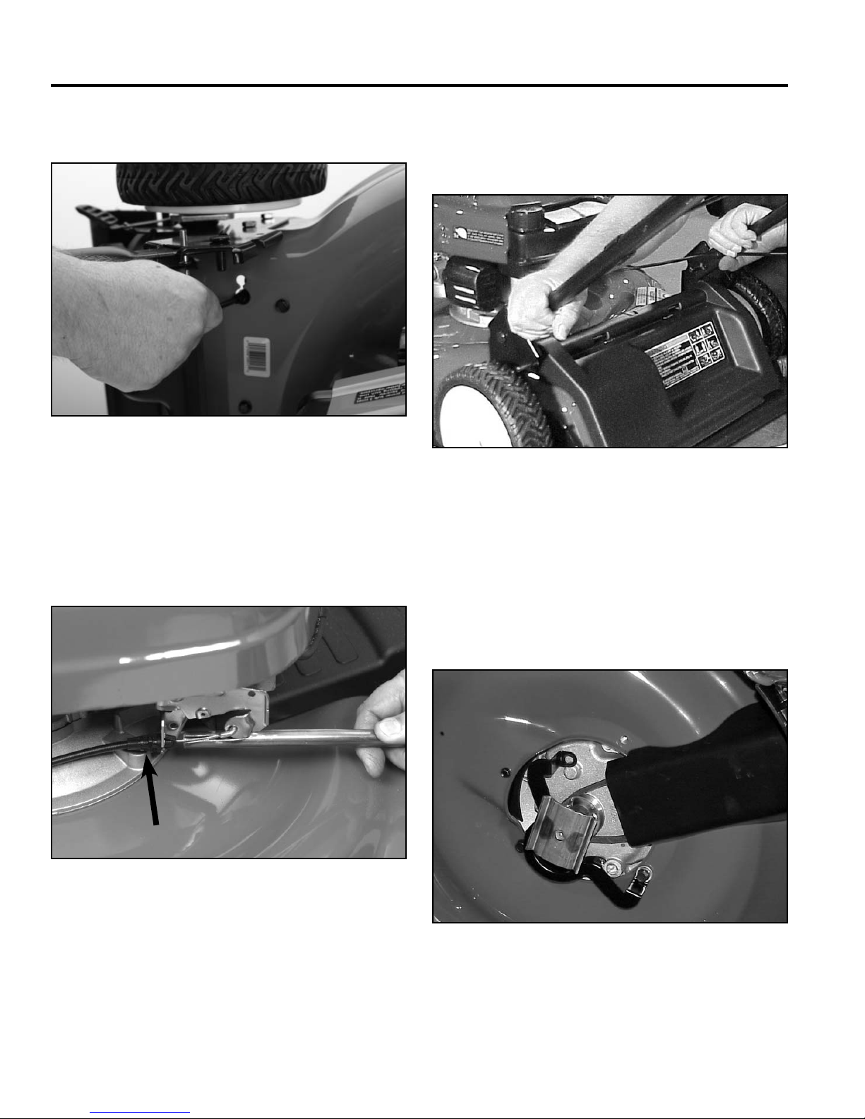
10. Remove the stop cable from the engine (Fig. 067)
and disconnect the self propel cable spring from the
transmission.
11. Pinch the ends of the lower handle together to
disengage them from the pins on the HOC plates
(Fig. 068).
Fig 068 MVC-737
12. Tip the mower onto its right side (carburetor up) and
remove the blade.
13. Remove one of the belt guide screws and loosen
the other enough to pivot the guide away (Fig. 069).
Do not bend the belt guide. Slide the pulley/blade
adapter and belt off the crankshaft.
A
Fig 067 DSC-017
A. Stop cable
3-12 WPM Drive Systems Manual
Fig 069 MVC-738
Page 51
SINGLE SPEED BEVEL GEAR TRANSMISSION
14. Place the mower right side up and remove the three
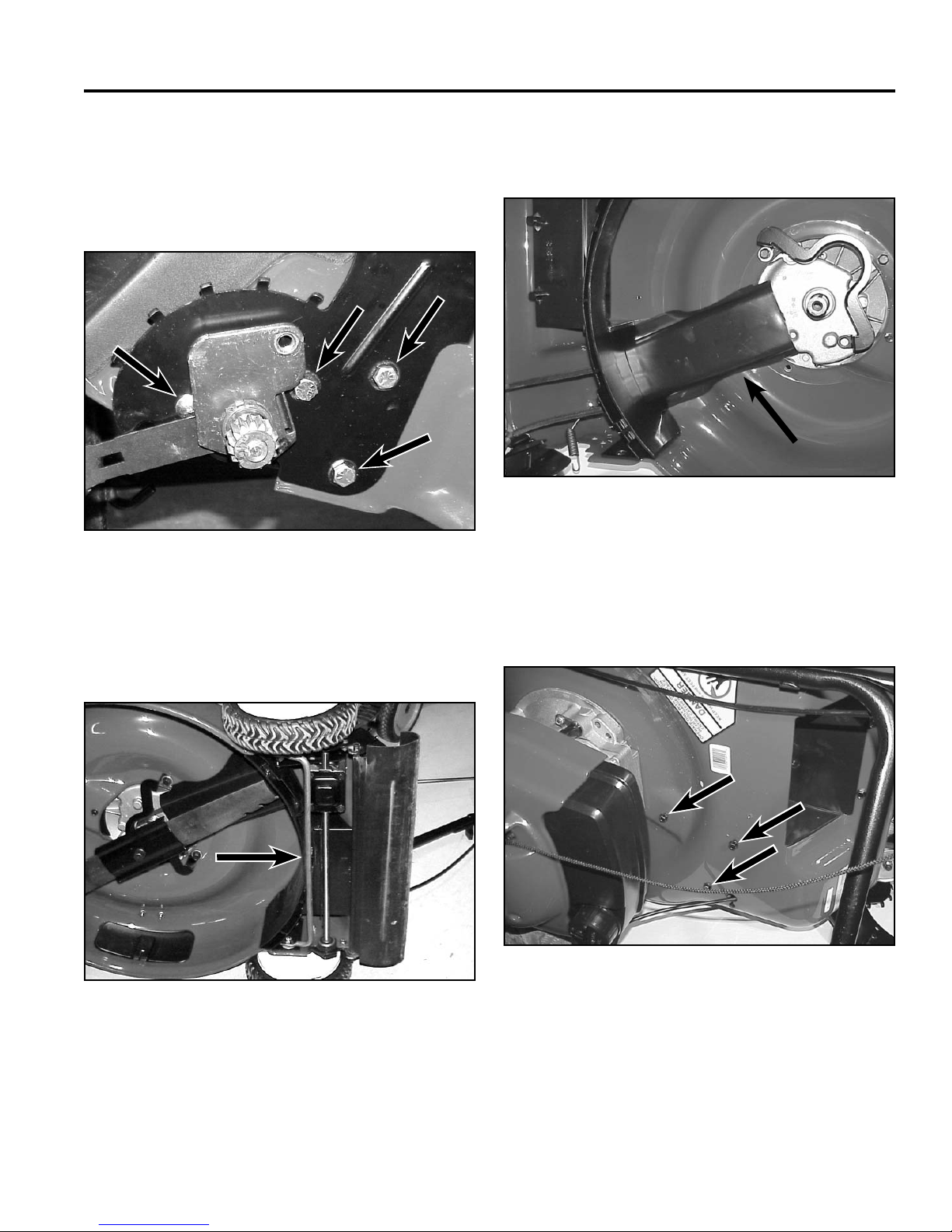
hex head and one Allen head cap screws on each
side that hold the height of cut plates to the chassis
(Fig. 070). The transmission assembly will now drop
down.
16. The belt cover must be removed in order to remove
the belt (Fig. 072).
Fig 072 MVC-743
A. Belt cover
Fig 070 MVC-848
A
15. There is a cross brace underneath the mower that is
held in place by two of the cap screws shown above
(Fig. 071).
Fig 071 MVC-852
17. Remove 3 screws that secure the belt cover to the
housing (Fig. 073).
Fig 073 MVC-744
3-13WPM Drive Systems Manual
Page 52
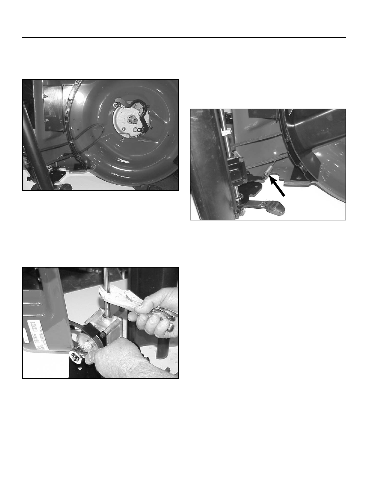
SINGLE SPEED BEVEL GEAR TRANSMISSION
18. Pull the belt cover out from under the rear wall and
the belt is exposed (Fig. 074).
Fig 074 MVC-745
19. Clamp the axle with locking pliers and remove the
pulley nut and transmission pulley (Fig. 075).
Do not bend the belt guide. The pulley must be lifted
up slightly to slip the belt off.
20. The cable may be unhooked from the arm on the
transmission to help prevent cable damage (Fig.
076).
Note: It is not necessary to remove the transmission
to replace the control cable.
Fig 076 MVC-741
21. Pull the belt towards the crankshaft and remove.
Fig 075 MVC-740
If only the belt is to be replaced, install a new one
now. Reverse the process to assemble.
If transmission service is necessary proceed as
follows.
3-14 WPM Drive Systems Manual
Page 53
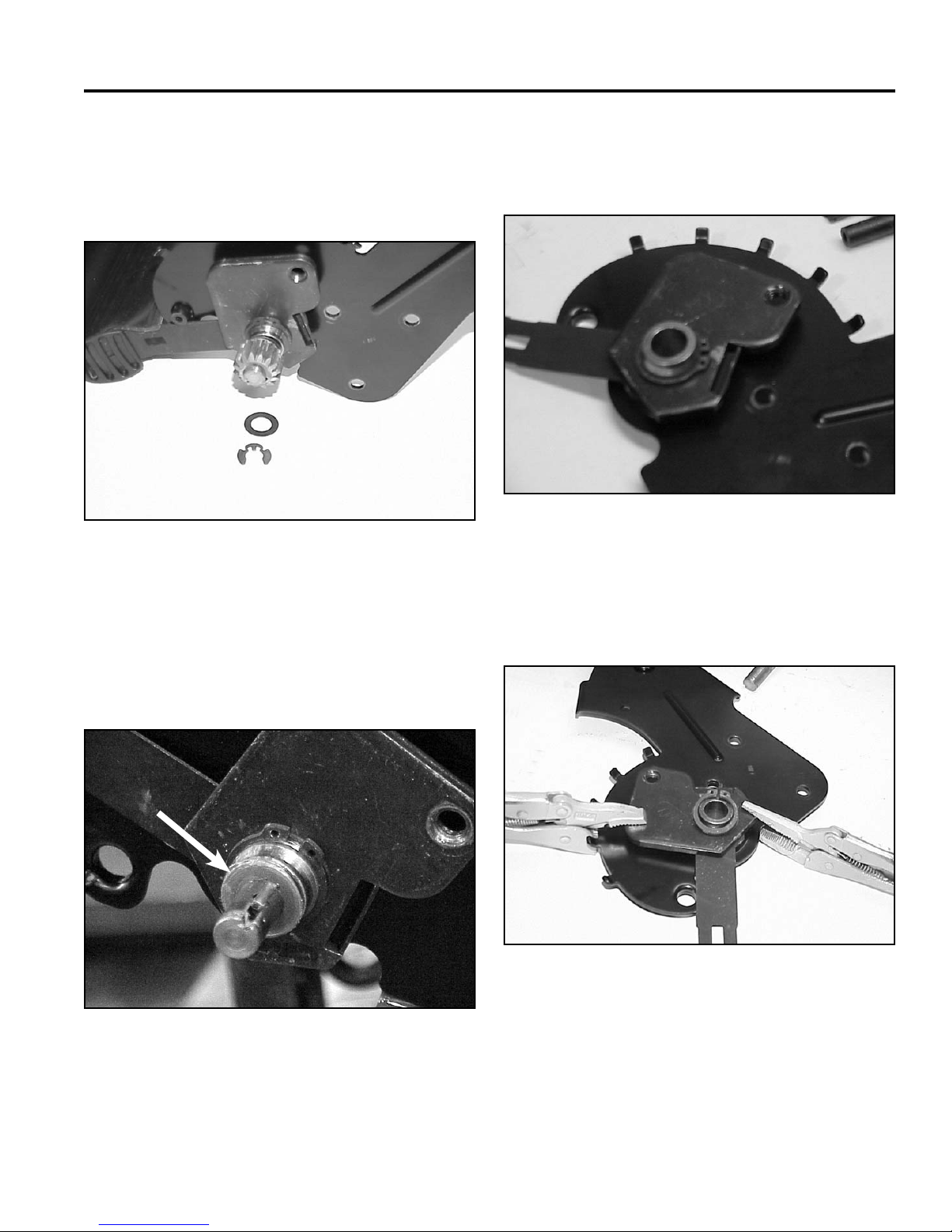
SINGLE SPEED BEVEL GEAR TRANSMISSION
Rear Axle Disassembly
1. Remove the klip rings and thrust washers that
secure the pinions to the axle (Fig. 077).
Fig 077 MVC-746
2. When removing the pinions, note that there is a
spring-loaded key under them.
4. The pivot assembly will slide off the axle. This
includes the bearing, bearing retainer, HOC plate,
spring arm, and pivot arm (Fig. 079).
Fig 079 MVC-747
5. Clamp the pivot assembly with 2 pairs of locking
pliers or other clamps and remove the snap ring
(Fig. 080).
3. Remove the other thrust washer and retaining ring
holding the pivot assembly to the axle (Fig. 078).
Fig 078 MVC-850
Fig 080 MVC-748
3-15WPM Drive Systems Manual
Page 54
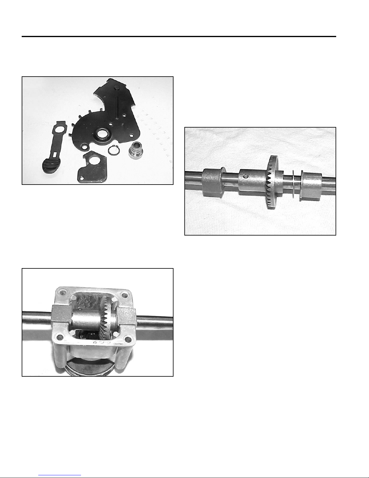
SINGLE SPEED BEVEL GEAR TRANSMISSION
6. You can now release the clamps and separate the
HOC plate, spring arm, and pivot arm (Fig. 081).
Fig 081 MVC-750
Transmission Disassembly
2. Since the pulley was previously removed, the input
shaft will now slip out of the transmission case.
3. If the input bearing is to be removed, press it out
now.
4. Slide the bearings and thrust washer off the axle.
Drive the roll pin out and the bevel gear can be
removed (Fig. 083).
1. Remove the 4 screws holding the cover on the
transmission. The axle, bearings, and bevel gear
can be lifted out (Fig. 082).
Fig 082 MVC-462
Fig 083 MVC-470
Transmission Assembly
Assemble in reverse order.
3-16 WPM Drive Systems Manual
Page 55
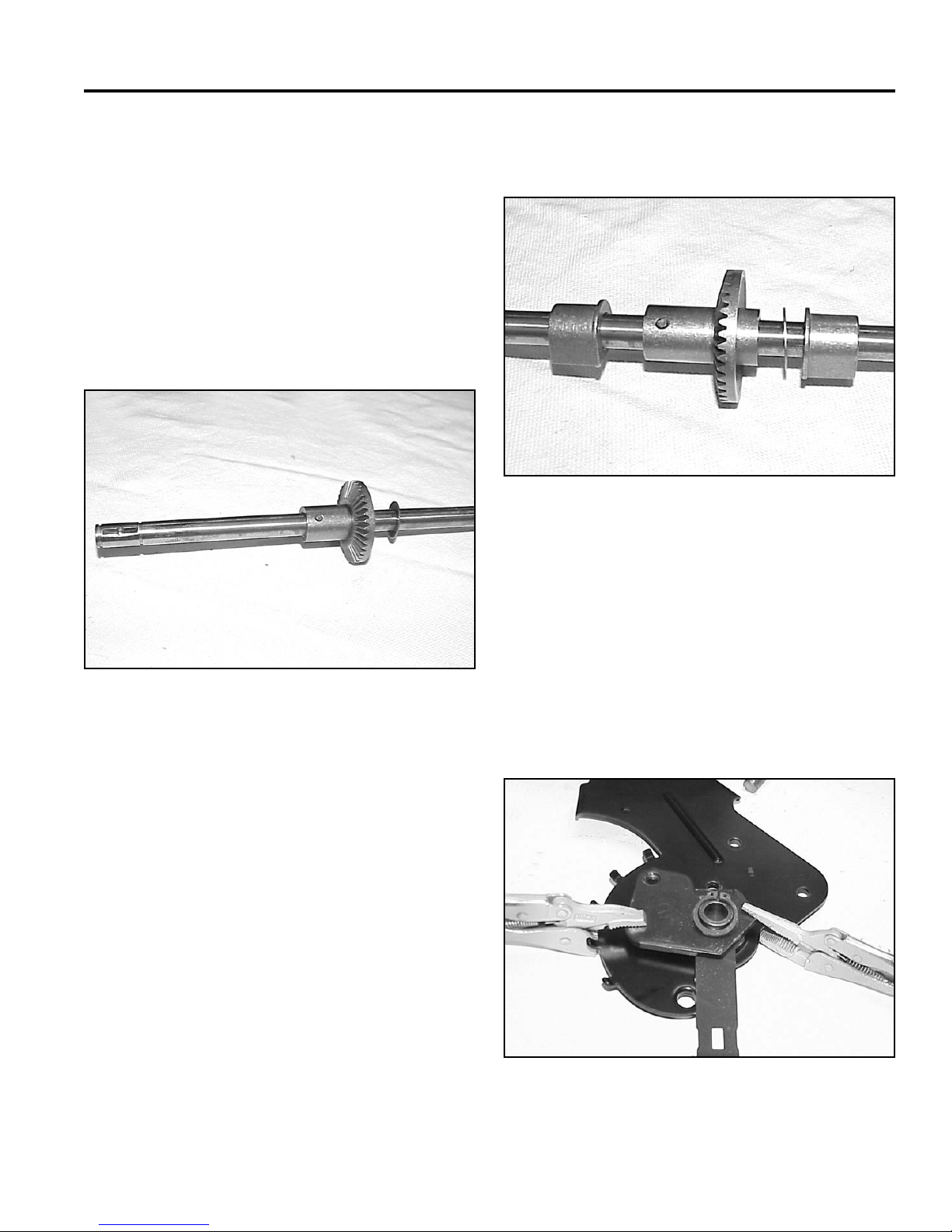
SINGLE SPEED BEVEL GEAR TRANSMISSION
Axle Assembly Tips
1. The same axle is used for both front and rear wheel
drive models. There are two holes in the axle about
one inch apart.
Rear wheel drive models use the hole about 4-3/4”
(12cm) from the end. Slip the gear on such that the
teeth and the longest hub face the short end of the
axle. Drive the pin into place. A double check is that
neither of the pin holes should be visible when the
gear is installed (Fig. 084).
3. Install the transmission bearings with the fl ange
facing the gear (Fig. 085).
Fig 085 MVC-470
4. Fill the transmission approximately 2/3 full with #2
Lithium base grease (1.5 oz or 43gm).
Fig 084 MVC-469
A. Gear B. Thrust washer
2. Install the thrust washer on the side of the gear with
the shortest hub, away from the gear teeth (Fig.
084).
5. Assemble the bearing, bearing retainer, HOC plate,
spring arm, and pivot arm. Use two vise grips or
clamps to compress the assembly so the snap ring
can be installed (Fig. 086).
Note: Install the snap ring with the sharp edge
facing away from the spring arm.
Fig 086 MVC-748
3-17WPM Drive Systems Manual
Page 56
SINGLE SPEED BEVEL GEAR TRANSMISSION
6. Coat the axle, key, and spring with #2 molybendum
disulfi de grease or anti-seize compound before
installing the pinion (Fig. 087).
Fig 087 MVC-472
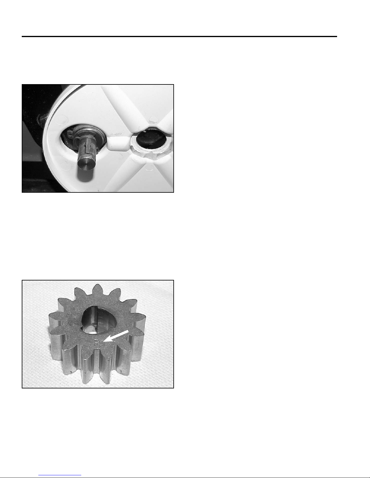
7. The wheel pinion is marked with an R and L for right
and left. Identify right and left from the operator’s
position (Fig. 088). On the right side, the R should
face outward. The letter L should face outward on
the left side. If the wheel pinions are reversed, the
wheels will not drive.
R
Fig 088 MVC-474
Note: See Chapter 5 for more information on Wheel
Clutches.
3-18 WPM Drive Systems Manual
Page 57
SINGLE SPEED BEVEL GEAR TRANSMISSION
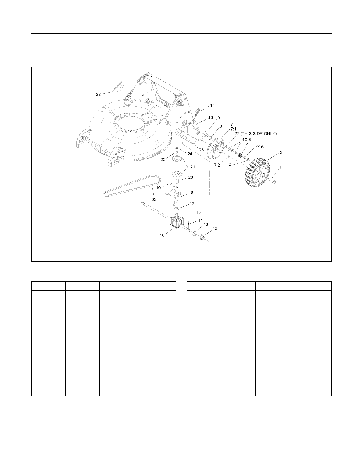
LAWN-BOY INSIGHT TRANSMISSION REMOVE AND REPLACE
3352-960 Rev B
4
Rear Axle and Transmission Assembly
Ref. No. Qty Description
1
2
3
4
6
7
7:1
7:2
8
9
10
11
12
13
2
2
4
2
6
2
1
1
2
1
2
2
2
2
Bolt-Shoulder
Rear Wheel ASM
Klipring-Locking
Gear-Pinion, 15T
Washer-Thrust
Wheel Cover ASM
Cover-Wheel
Washer-Stepped
Ring-Retaining
Arm-Rear, Pivot, LH
Arm-Spring, Rear
Knob-Lever, HOC
Retainer-Bearing, HOC
Bearing-Ball
Fig 089 3352-960(6)
Ref. No. Qty Description
14
15
16
17
18
19
20
21
22
23
24
25
27
28
2
2
1
1
1
2
1
2
1
1
1
1
1
1
Spring-Compression
Key
Transmission ASM
Washer-Shield
Bracket-Transmission
Screw-HWH
Spacer
Pulley-Half
V-Belt
Washer-Flat
Nut-Lock
Shield-Trailing
Washer
Arm-Rear Pivot, RH
3-19WPM Drive Systems Manual
Page 58
SINGLE SPEED BEVEL GEAR TRANSMISSION
A
Transmission Removal & Belt Replacement
The following steps will show one method of replacing
the belt or removing the transmission on the Lawn-Boy
Insight mowers.
1. Prepare the mower. Drain the gas and oil and
disconnect the spark plug wire.
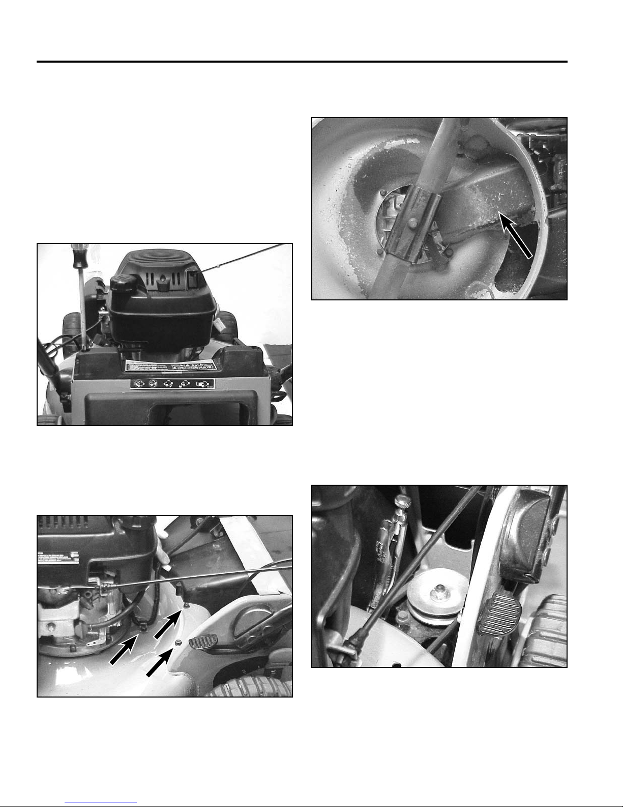
2. Remove two screws that secure the rear cover (Fig.
090).
4. The belt cover will drop off the bottom (Fig. 092).
A
Fig 092 MVC-288
A. Belt cover
5. If you have an electric start model, remove the
battery and battery box.
Fig 090 MVC-285
3. Remove the 3 belt cover screws (Fig. 091).
Fig 091 MVC-286
6. Clamp the axle with a locking pliers and remove the
nut from the transmission pulley. If you are using an
air wrench, you may not need to hold the axle (Fig.
093).
Fig 093 MVC-291
3-20 WPM Drive Systems Manual
Page 59
SINGLE SPEED BEVEL GEAR TRANSMISSION
7. Lift the top half of the transmission pulley off. If just
replacing the belt, push the belt into the cutting
chamber and slip the belt over the blade. Reverse
the process to install the new belt (Fig. 094).
Note: Do not get anti-seize on the belt or the drive
will slip.
Fig 094 MVC-292
9. Bend the trailing shield slightly in the middle and
remove it from the mower. Rotate both rear spring
arms down to disengage them from the mower
housing (Fig. 096).
Fig 096 MVC-295
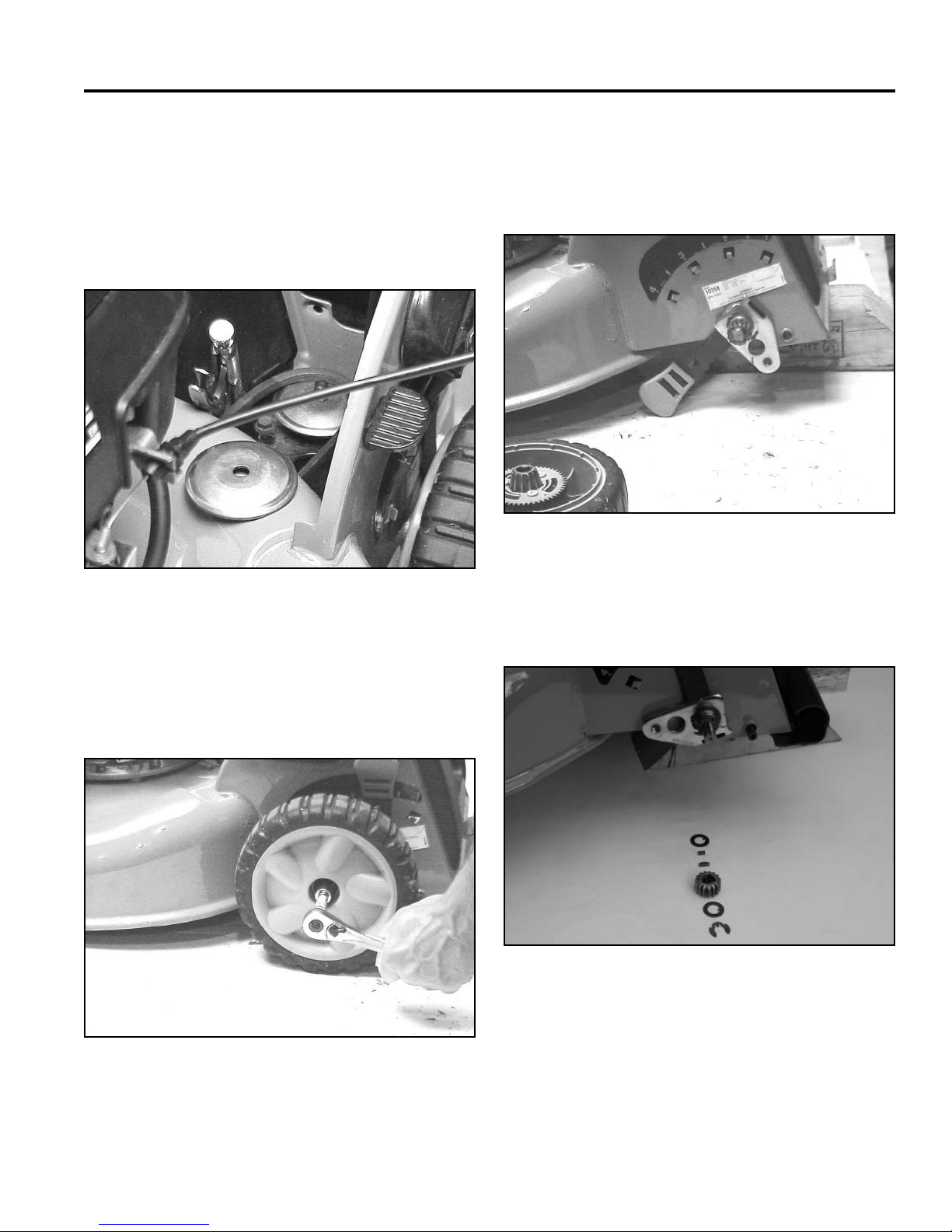
10. Remove klip ring, thrust washer, pinion, key spring
and thrust washer (Fig. 097).
If the transmission is to be removed, continue:
8. Support the back of the mower on a wood block and
remove the rear wheels (Fig. 095).
Fig 095 MVC-294
Fig 097 PICT-1914a
3-21WPM Drive Systems Manual
Page 60
SINGLE SPEED BEVEL GEAR TRANSMISSION
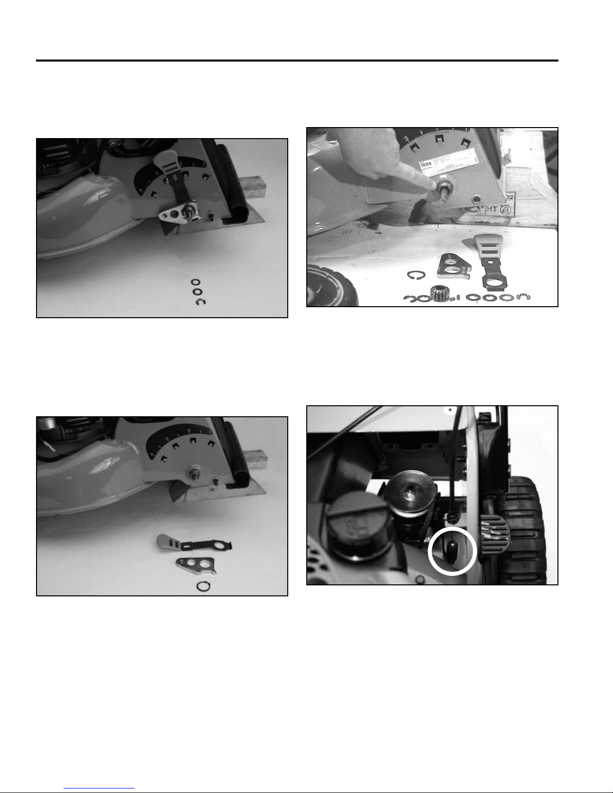
11. Remove klip ring, keyed thrust washer, and standard
thrust washer (left side of mower has the standard
thrust washer, right side does not) (Fig. 098).
Fig 098 PICT-1915a
12. Remove the snap ring, pivot arm and spring arm
(Fig. 099).
13. Push the bearings and bearing retainers inward,
towards the transmission (Fig. 100).
Fig 100 MVC-297
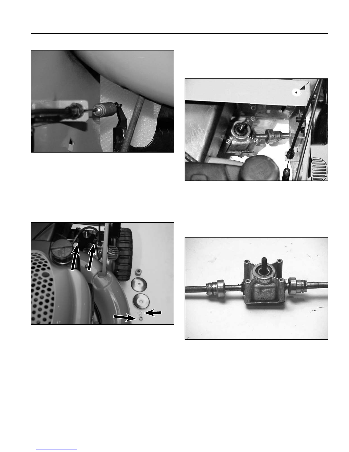
14. Unhook the traction cable from the transmission belt
guide (Fig. 101 and Fig 102).
Fig 099 PICT-1921a
3-22 WPM Drive Systems Manual
Fig 101 PICT-1923
Page 61
SINGLE SPEED BEVEL GEAR TRANSMISSION
A
B
C
D
E
F
Fig 102 MVC-211x1
16. Push the transmission to the left, as shown, and
rotate to clear the tunnel. Drop the left side down,
then pull the assembly out to the left side (Fig. 104).
15. Remove the nut, washer, 2 pulley halves, and
spacer from the transmission input shaft. Remove 2
screws securing the belt guide to the transmission
(Fig. 103).
B
A
F
Fig 103 PICT-1926
A. 2 screws on top D. Pulley half
of transmission E. Washer
B. Spacer F. Nut
C. Pulley half
C
D
E
Fig 104 MVC-300
17. The last step is to slide the bearings and bearing
retainers off the axle (Fig. 105).
Fig 105 MVC-301
3-23WPM Drive Systems Manual
Page 62
SINGLE SPEED BEVEL GEAR TRANSMISSION
Transmission Disassembly
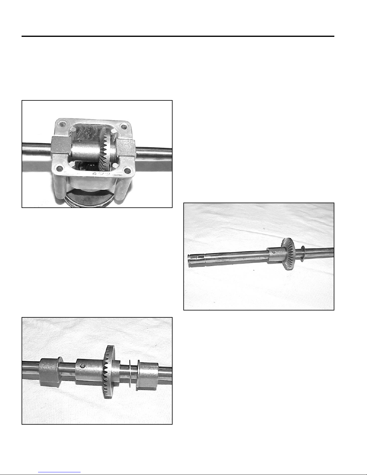
1. Remove the 4 screws holding the cover on the
transmission. The axle, bearings, and bevel gear
can be lifted out (Fig. 106).
Fig 106 MVC-462
Transmission Assembly & Installation
Assemble in reverse order. See Axle Assembly and
Installation Tips following.
Axle Assembly Tips
1. The same axle is used for both front and rear wheel
drive models. There are two holes in the axle about
one inch apart.
Rear wheel drive models use the hole about 4-3/4”
(12cm) from the end. Slip the gear on such that the
teeth and the longest hub face the short end of the
axle. Drive the pin into place. A double check is that
neither of the pin holes should be visible when the
gear is installed (Fig. 108).
2. Since the pulley was previously removed, the input
shaft will now slip out of the transmission case.
3. If the input bearing is to be removed, press it out
now.
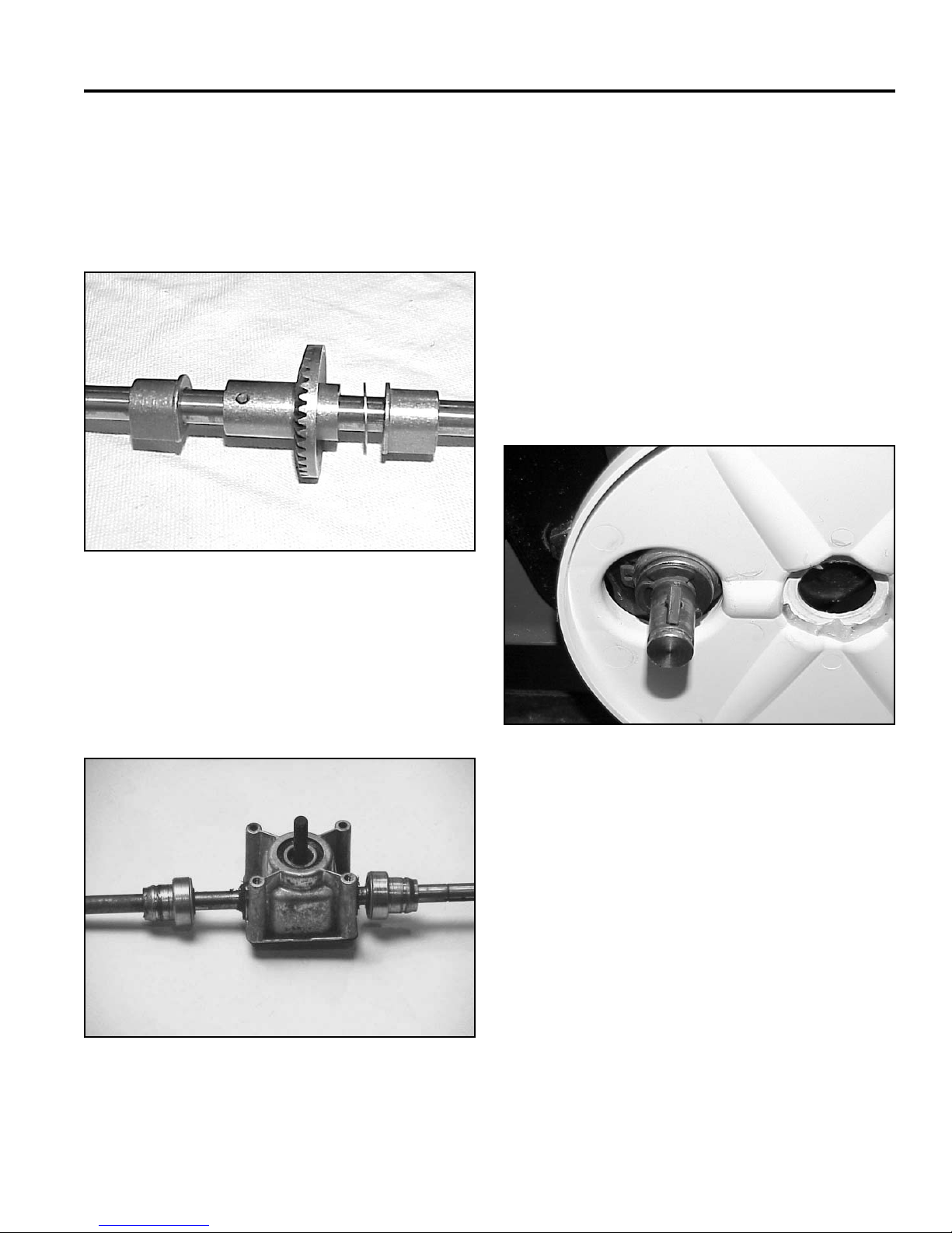
4. Slide the bearings and thrust washer off the axle.
Drive the roll pin out and the bevel gear can then be
removed (Fig. 107).
Fig 108 MVC-469
Fig 107 MVC-470
3-24 WPM Drive Systems Manual
Page 63
SINGLE SPEED BEVEL GEAR TRANSMISSION
2. Install the thrust washer on the side of the gear with
the shortest hub, away from the gear teeth (Fig.
108).
3. Install the transmission bearings with the fl ange
facing the gear (Fig. 109).
Fig 109 MVC-470
Transmission Installation Tips
1. Reconnect the cable to the belt guide and install the
washer and spacer before installing the guide on the
transmission.
2. Install the snap rings and klip rings with the sharp
side out (in the direction of the force). The left end
of the axle uses the extra thrust washer, the one
without the tab. Install the snap ring, the regular
thrust washer then the thrust washer with the tab.
3. Coat the axle, key, and spring with #2 molybendum
disulfi de grease or anti-seize compound before
installing the pinion (Fig. 111).
4. Fill the transmission approximately 2/3 full with #2
Lithium base grease (1.5 oz or 43gm).
5. Assemble the bearings and bearing retainers; install
the transmission in the housing (Fig. 110).
Fig 110 MVC-301a
Fig 111 MVC-472
3-25WPM Drive Systems Manual
Page 64
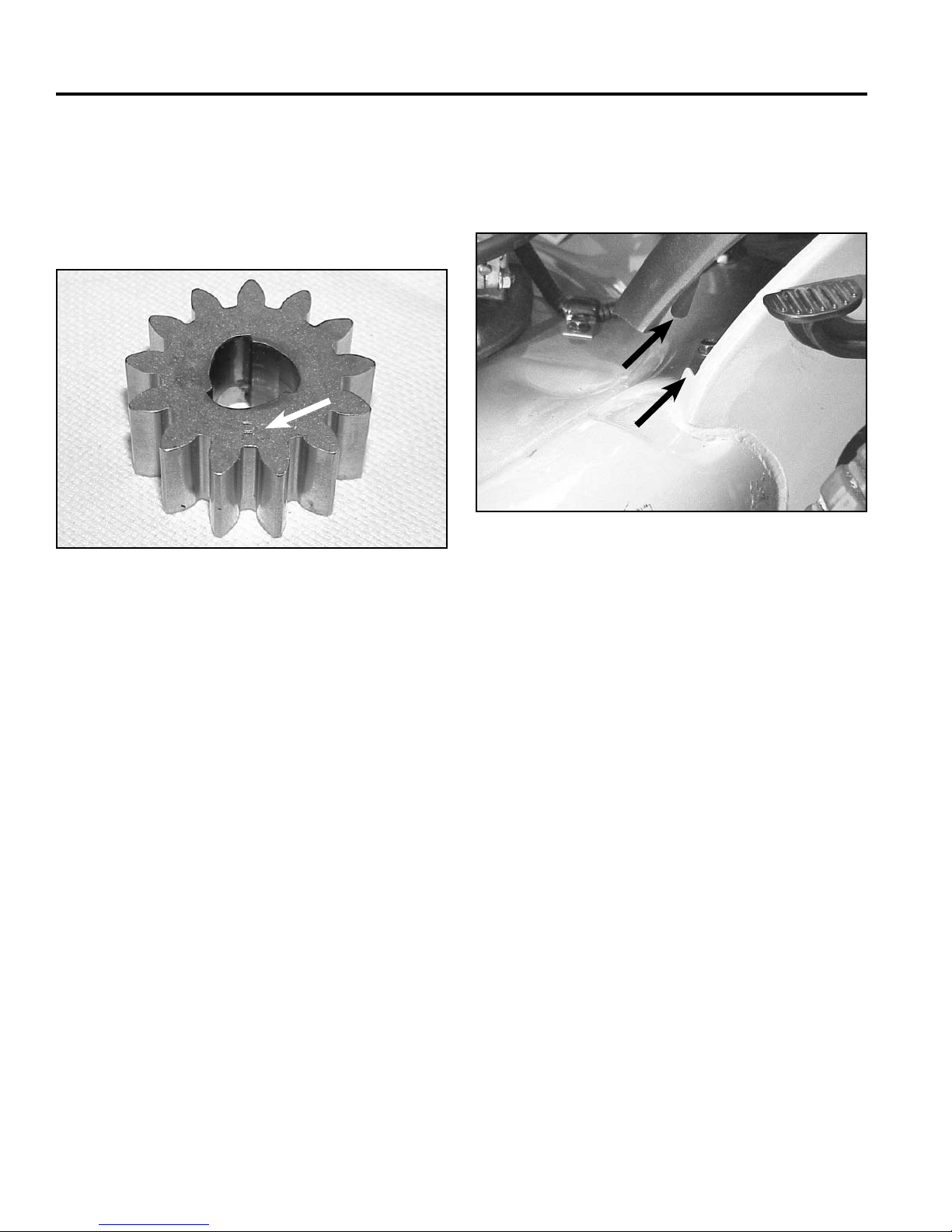
SINGLE SPEED BEVEL GEAR TRANSMISSION
4. The wheel pinion is marked with an R and L for right
and left. Identify right and left from the operator’s
position (Fig. 112). On the right side, the R should
face outward. The letter L should face outward on
the left side. If the wheel pinions are reversed, the
wheels will not drive.
R
Fig 112 MVC-474
7. When installing the rear cover, note the bosses on
the back side of the cover. They must go behind the
notch in the chassis to secure the cover. The top of
the cover is retained with screws (Fig. 113).
A
B
Fig 113 MVC-303
A. Boss B. Notch
5. Make sure the stepped washer is properly seated
in the wheel cover. The best way is to assemble the
wheel, wheel cover, and wheel bolt, then put them all
on the mower together.
6. Do not use an impact wrench on the crankshaft belt
guide screws. Over-tightening can cause the belt
guide to deform and cause the belt not to declutch
properly. Tighten fi rmly with a ratchet.
Note: Wheel Clutch Service - see Spring Ratchet
Key Style Clutch, page 5-8. Control Cable
Adjustment - see Handles & Control Cables.
3-26 WPM Drive Systems Manual
Page 65

THREE SPEED TRANSMISSION
Worm Drive Transmission . . . . . . . . . . . . . . . . . . . . . . . .
Single Speed Spur/Bevel Gear Transmission . . . . . . . . . . . . .
Single Speed Bevel Gear Transmission . . . . . . . . . . . . . . . .
Three Speed Transmission . . . . . . . . . . . . . . . . . . . . . . .
Wheel Pinion Clutch . . . . . . . . . . . . . . . . . . . . . . . . . . .
1
2
3
4
5
Blade Brake Clutch Systems (BBC), Blade Override
System (BOS), Blade Clutch Systems (BCS) . . . . . . . . . . . . .
Handles and Control Cables . . . . . . . . . . . . . . . . . . . . . .
Self-Propel Belt Replacement . . . . . . . . . . . . . . . . . . . . . .
6
7
8
4-1WPM Drive Systems Manual
Page 66
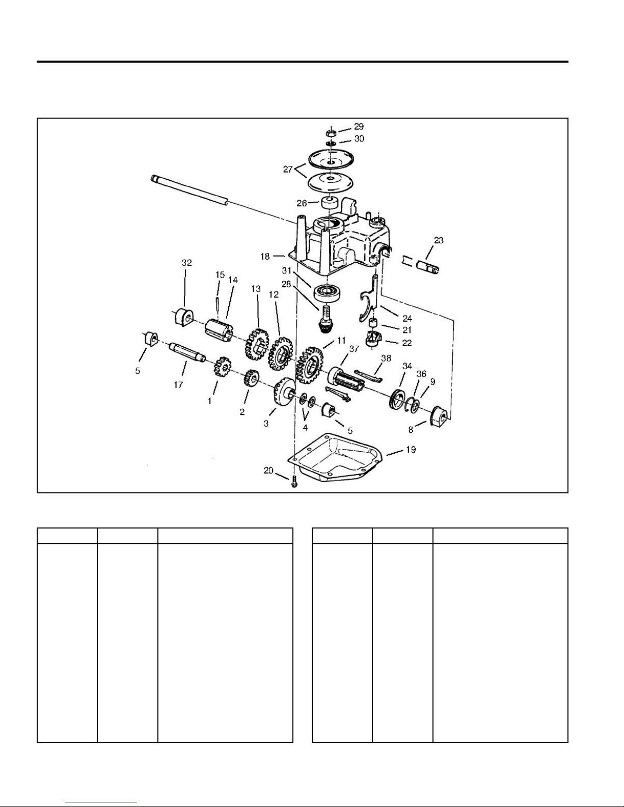
THREE SPEED TRANSMISSION
GEARCASE ASSEMBLY
Ref. No. Qty Description
1
2
3
4
5
8
9
11
12
13
14
15
17
18
19
20
4-2 WPM Drive Systems Manual
1
1
1
2
2
1
1
1
1
1
1
1
1
1
1
6
Pinion-25T
Pinion-20T
Gear-15t Spur, 37t Bevel
Washer - Thrust
Bushing
Bushing - Output
Washer
Gear-49 T
Gear-44 T
Gear-39 T
Sleeve - Gear
Pin - Spring
Shaft - Intermediate
Case - Gear, Upper
Cover - Case, Gear
Screw - Tapping
Fig 114 gearcaseassy
Ref. No. Qty Description
21
22
23
24
26
27
28
29
30
31
32
34
36
37
38
1
1
1
1
1
2
1
1
1
1
1
1
1
1
2
Bushing - Yoke
Retainer - Fork, Shift
Shaft - Output
Yoke - Shift
Spacer
Pulley - Half
Gear - Pinion, Bevel
Nut - Lock NI
Washer - Flat
Bearing - Ball
Bushing - Output
Collar - Shift
Clip - Spring
Sleeve - Key, Shift
Key - Shift
Page 67
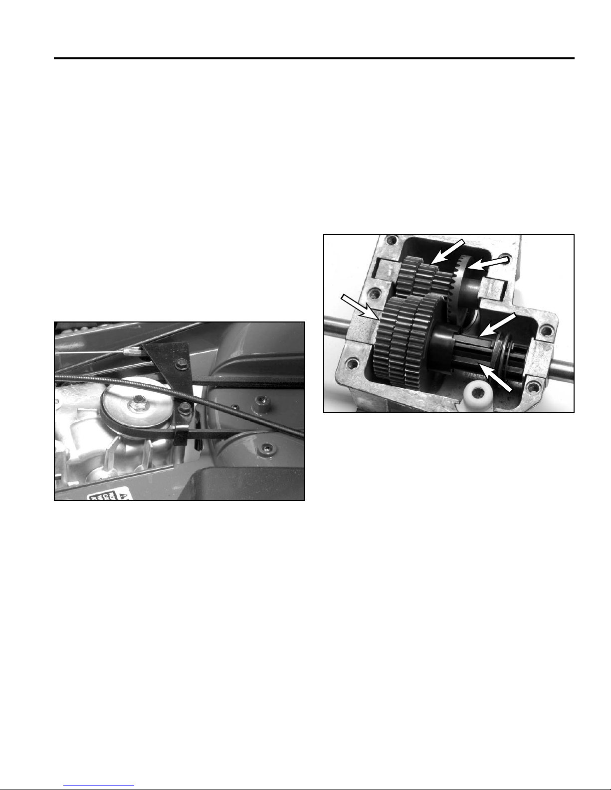
THREE SPEED TRANSMISSION
A
B
C
D
E
OPERATION
Input System:
Power is transferred from the engine to the transmission
by a belt. The self-propel pulley at the engine is keyed
to the crankshaft. The pulley on top of the transmission
is supported by a ball bearing and drives a pinion
gear inside the transmission. Tensioning of the belt is
accomplished by pivoting the transmission. When the
operator squeezes the control bar toward the handle,
a control cable tilts the transmission backward and
tensions the belt. When the control bar is released,
gravity pivots the transmission forward to loosen the belt.
Belt guides at the engine pulley and atop the
transmission ensure disengagement by forcing the belt
to loop around the engine pulley (Fig. 115).
Speed Reduction System:
Speed reduction is accomplished by two sets of gears
– one set on the intermediate shaft and the other set on
the output shaft. The gears on the intermediate shaft
are powdered metal and ride on a hexagonal shaft
supported on each end by oil impregnated bushings.
These gears are driven by the pinion at the bottom of the
input shaft. The driven bevel gear turns the shaft so that
all three gears on the intermediate shaft have the same
rotational velocity (Fig. 116).
A
B
E
C
Fig 115 3428-0196
D
Fig 116 3428-0058
A. Intermediate shaft C. Shift key
& gears D. Gear sleeve
B. Bevel gear E. Output shaft & gears
4-3WPM Drive Systems Manual
Page 68
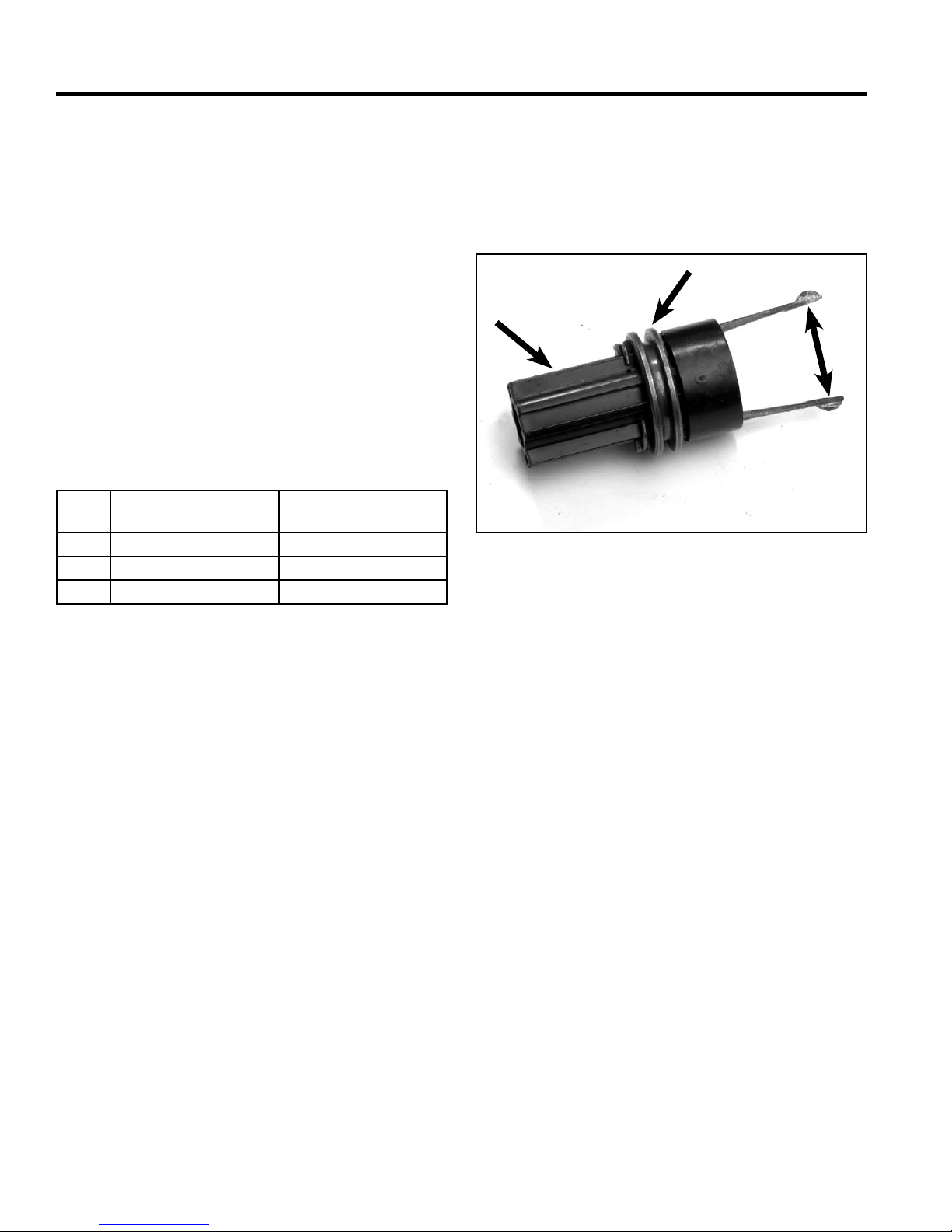
THREE SPEED TRANSMISSION
There are also three gears on the output shaft. These
three gears rotate freely on the gear sleeve. The gear
sleeve is coupled to the output shaft with a roll pin so
the gear sleeve always rotates with the output shaft. The
gear selection system determines which one of these
three gears will be coupled with the gear sleeve and the
output shaft. This determines the fi nal drive ratio.
Gear Selection System:
Gear selection is determined by moving sliding shift
keys in a sleeve that is fi xed to the output shaft. These
keys engage one of the three gears that rotate on the
gear sleeve. Once the key engages one of the gears,
that gear will rotate the output shaft. Table 1 shows
approximate speeds in gears for two different engine
speeds.
Table 1
Gear Ground Speed @
3000 RPM
1 1.8 mph (2.9km/h) 1.2 mph (1.9km/h)
2 2.7 mph (4.4km/h) 1.8 mph (2.9km/h)
3 3.8 mph (6.1km/h) 2.5 mph (4.3km/h)
Ground Speed @
2000 RPM
The shift keys are retained on one end by the shift
collar. Movement of the shift fork positions the shift collar
and shift key. The shift fork is supported, both top and
bottom, by nylon bushings for smooth operation and long
wear (Fig. 117).
B
A
C
Fig 117 3428-0065
A. Gear Sleeve C. Keys
B. Shift Collar
The operator controls movement of the shift fork by
means of the gear selection control and cable.
Note: There are no shift detents in or on the
transmission on 1988 and newer mowers.
4-4 WPM Drive Systems Manual
Page 69
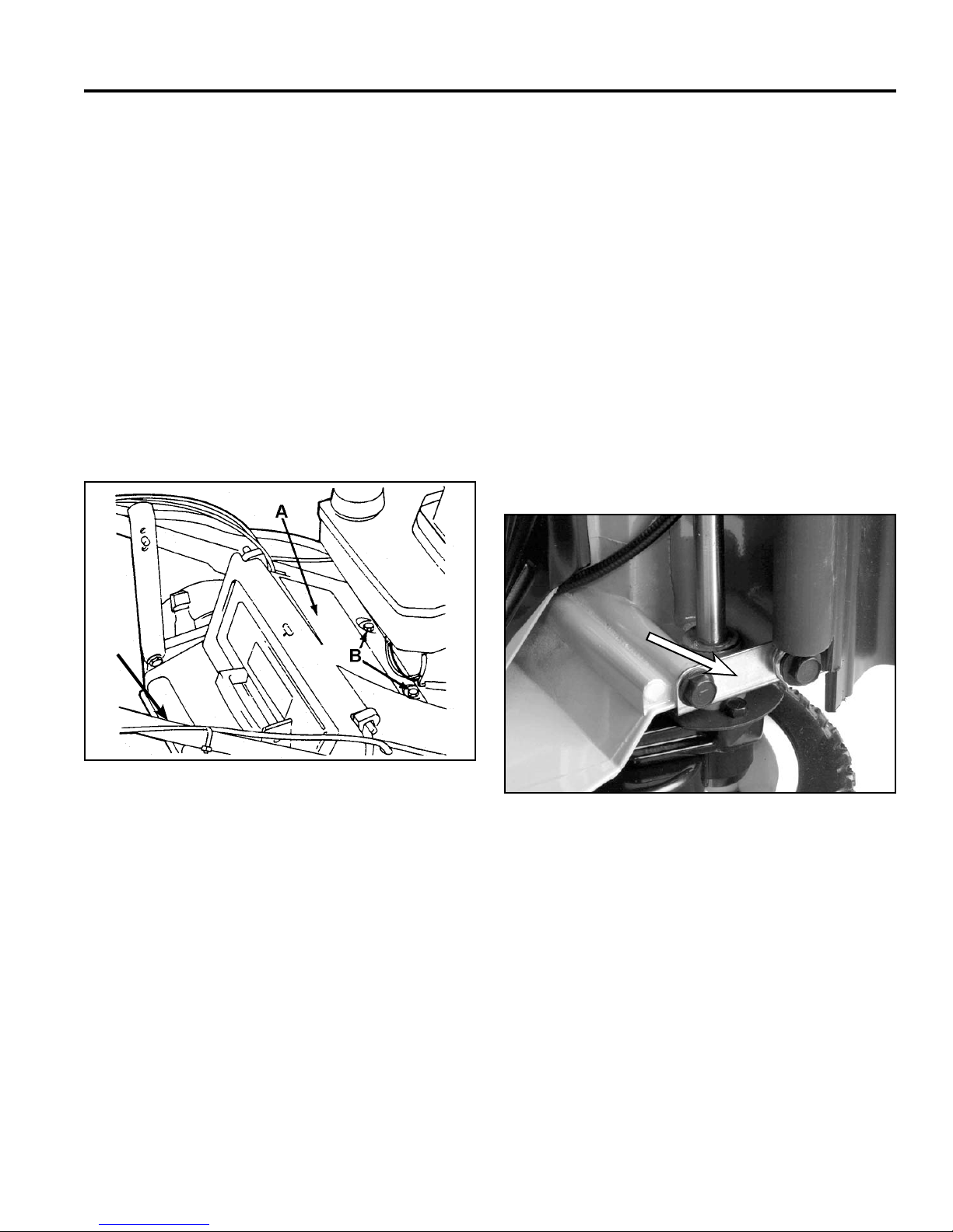
THREE SPEED TRANSMISSION
A
Removal - Toro Vacu Power/Lawn-Boy
Medallion Models
Complete transmission removal on the Toro Vacu
Power/Lawn-Boy Medallion mower is quite easy and is
recommended for most self-propel system repairs.
1. Remove the spark plug lead from the engine to
prevent accidental starting. Drain the fuel and oil.
2. Place the ground speed selector in neutral. This will
make it easier to remove the speed selection cable
later.
3. Remove the two fl anged head self-tapping screws
securing the screen panel to the housing and
remove the panel (Fig. 118).
4. Remove the black plastic transmission cover from
the top rear of the housing.
5. Remove the two fl anged head self-tapping
screws securing the belt cover to the top of the
transmission. Pull the cable from belt guide and
remove the belt guide.
6. Remove the transmission access cover from the rear
of the housing by pressing from underneath.
7. Loosen the gear selection control cable clamp screw
until the cable comes free. Do not attempt to remove
the gear selection cable from the control arm at this
time.
8. Turn the mower onto its right side and remove the
four fl anged head self-tapping screws securing the
end caps to the housing (Fig. 119).
C
Fig 118 fi g 94
A. Screen panel C. Transmission access
B. Screws cover
A
Fig 119 3428-0121
A. End cap
9. Slowly pull the transmission from the housing being
very careful not to damage the gear selection cable.
Once clear of the housing, rotate the assembly until
the cable can be safely removed.
4-5WPM Drive Systems Manual
Page 70
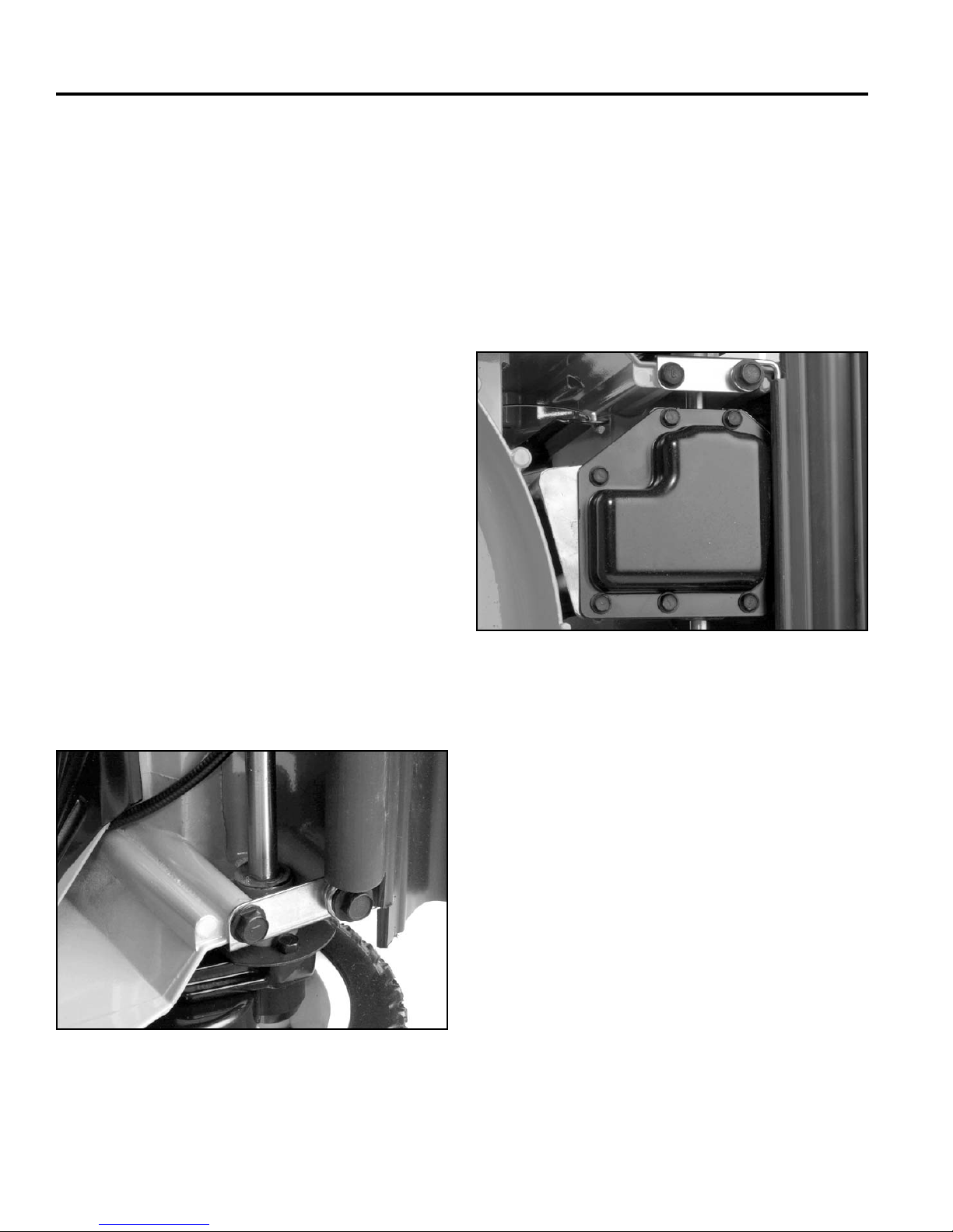
THREE SPEED TRANSMISSION
Removal - Recycler/Rear Bagger Chassis
To remove the transmission from the chassis, raise the
rear and support it with blocks.
1. Remove both rear wheels and wheel covers.
2. Remove the rocking key clutches (see “Wheel Pinion
Clutch” on page 5-3).
3. Slide the pivot arm and spring arm off the axles.
4. Remove the belt cover. Loosen the belt guide and
slip the belt off the pulley. Disconnect shift and clutch
cables.
5. Slide the transmission to the right to slip the short
end of the axle out of the chassis.
Alternate Method
1. Pivot both spring arms until they point straight.
Disassembly
Inspection of this transmission can be accomplished
without removing the pivot arm assembly from the output
shaft. Only if components on the output shaft require
replacement will pivot arm removal be necessary.
1. Remove the six fl anged head self-tapping screws
securing the transmission cover to the transmission
case. Remove the cover (Fig. 121).
2. Remove belt cover and belt.
3. Disconnect shift and clutch cables.
4. Remove 4 self-tapping screws securing end caps to
housing (Fig. 120).
Fig 120 3428-0121
Fig 121 3428-0120
2. Before disassembling further, check for proper
operation of the input system, the gear reduction
system and gear selection system. For more
information on this, refer to “OPERATION” on page
4-3.
4-6 WPM Drive Systems Manual
Page 71
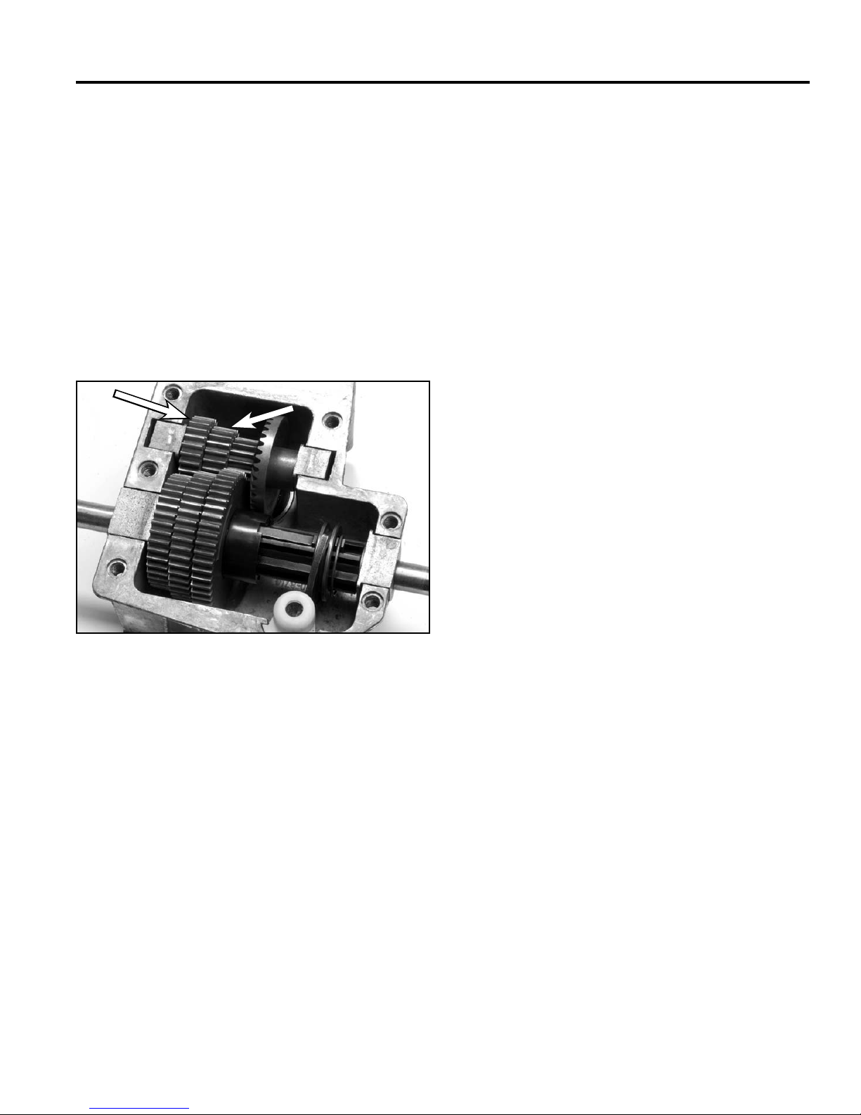
THREE SPEED TRANSMISSION
B
3. Removal of the input shaft and pulley assembly can
be diffi cult because the input pinion has a tendency
to turn as the pulley nut is loosened. This situation
can be addressed by using an impact wrench or by
removing the 20 (B) and 25 (A) tooth gears (Fig.
122) from the intermediate shaft and then putting
the intermediate shaft assembly back onto the
transmission. The hexagonal intermediate shaft
can then be held with a 7/16” end wrench while the
pulley nut is loosened.
Note: A cut-away transmission cover can be
fabricated to hold the intermediate shaft in
place to facilitate pulley nut removal.
A
B
5. Remove the cotter pin from the top of the shift fork
and remove the shift lever.
6. Carefully pull the output shaft from the transmission
case, clean, and inspect all components for wear
or damage. Check the input shaft ball bearing for
roughness or excessive drag and replace any parts
necessary. If ball bearing replacement is required,
press the ball bearing out using an arbor press.
7. If service of any of the output shaft gears, or the
gear selection system, is required, remove the left
pivot arm as described under “Rear Height-of-Cut
and Wheel Pinion Clutch – Disassembly” on page
5-4 and 5-5.
Note: It is possible to replace the shift keys and
spring clip without removing the pivot arm
if the roll pin securing the gear sleeve to the
output shaft is fi rst driven out. However, it
is not recommended since inspection of the
inside of the output gears is not possible.
8. Pull the output shaft bushing, the spacer, the shift
collar, the shift keys and spring clip, and the shift key
sleeve from the output shaft.
Fig 122 3428-0058
4. Remove the intermediate shaft from the transmission
and clean. Inspect all gears for wear, cracks, and/or
broken teeth. Inspect the bushings for excessive
wear. Replace any parts necessary. Be careful not to
lose the two spacers that fi t between the bevel gear
and the bushing.
9. Remove the three output shaft gears form the output
shaft.
10. Drive out the roll pin securing the gear sleeve to the
output shaft. Remove the gear sleeve and remaining
output shaft bushing. Inspect all parts for wear and
damage and replace if necessary.A. 25-tooth gear B. 20-tooth gear
Transmission - Assembly
The transmission uses 6 oz. (177cc) No. 2 lithium-based
grease as a lubricant. When assembling, be sure to coat
all moving components with grease to ensure proper
lubrication.
4-7WPM Drive Systems Manual
Page 72
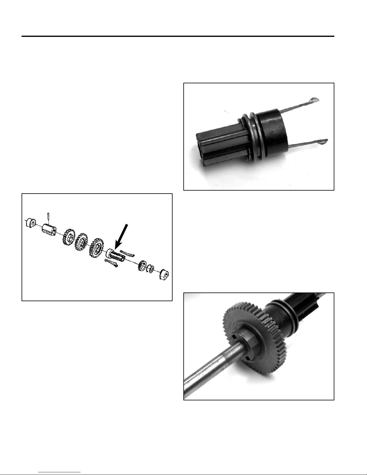
THREE SPEED TRANSMISSION
Output Shaft Assembly
1. Slide the output bushing onto the output shaft,
fl anged side last. Assemble from the end of the shaft
closest to the hole for the roll pin.
2. Slide the gear sleeve onto the output shaft, tabs last
and secure with a new roll pin.
3. Apply a light coat of lithium-based grease on the
output shaft under the output busing, on the gear
sleeve, and on the three output shaft gears. Slide
the three output shaft gears onto the gear sleeve,
notched sides last.
4. Slide the nylon shift key sleeve onto the output shaft,
large end fi rst. Make sure that it engages the tabs on
the gear sleeve (Fig. 123).
A
5. Coat the shift key sleeve with grease and prepare
the shift keys, shift collar, and spring clip for
assembly as shown in Figure 124.
Fig 124 3428-0065
6. Slide the shift key assembly into the shift key sleeve
until the shift collar bottoms out.
Fig 123 492-4733 fi g. 4-1
A. Shift key sleeve
7. Complete the output shaft assembly by sliding a
spacer washer and the other output bushing, fl anged
side fi rst, onto the output shaft. Don’t forget to coat
these components with a light coat of grease (Fig.
125).
Fig 125 3428-0066
4-8 WPM Drive Systems Manual
Page 73
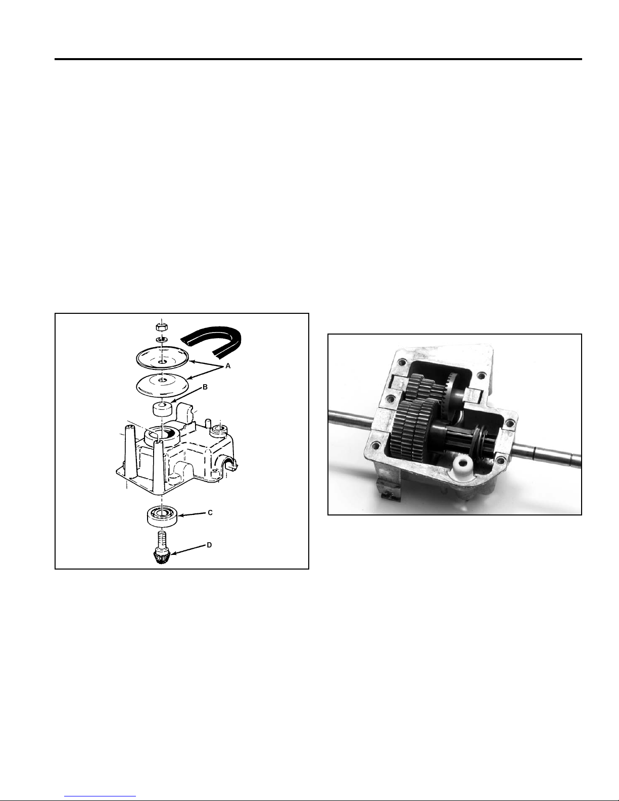
THREE SPEED TRANSMISSION
8. If the left pivot arm was removed for servicing,
reassemble now as described under “Rear Heightof-Cut and Wheel Pinion Clutch – Assembly” on
page 5-5.
Input Shaft Assembly
1. If the input bearing was removed, press a new one
into the gearcase using an arbor press. Press only
on the outer race or bearing damage may result.
2. Slide the input shaft and pinion through the ball
bearing and assemble the spacer and two pulley
halves as shown in Figure 126. Install a fl at washer
and a nylon locknut fi nger tight.
3. The input pulley nut can be tightened after complete
transmission assembly, or at this point using the
process in step 3, under Disassembly, page 4-7.
4. Slip the shift fork into the slot on the shift collar and
place the shift fork and output shaft assembly into
the transmission.
Note: The long end of the shift fork shaft should go
through the hole in the gearcase. Make sure
that the output bushings are trapped in the
proper locations. Note that the larger output
bushing holes on the longer end of the shaft
and the shorter output bushing goes on the
shorter end of the shaft.
5. Slide the yoke bushing onto the lower end of the
shift fork, then secure the shift fork with the white
nylon shift fork retainer (Fig. 127).
Fig 126 Fig. 100
A. Pulley C. Ball bearing
B. Spacer D. Pinion
Fig 127 3428-0059
A. Intermediate shaft C. Shift fork retainer
B. Flange
4-9WPM Drive Systems Manual
Page 74
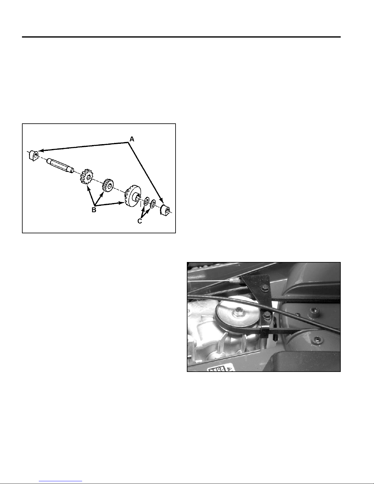
THREE SPEED TRANSMISSION
Intermediate Shaft Assembly
Note: Before assembling, coat the intermediate
shaft with No. 2 lithium-based grease. Apply a
light bead of lithium-based grease to fl ange.
1. Slip an intermediate shaft bushing onto the left end
of the intermediate shaft, fl anged end fi rst (Fig. 128).
2. Slide the intermediate shaft gears onto the
intermediate shaft in this order:
a. 25 tooth gear
b. 20 tooth gear
c. 15 tooth gear/bevel gear
3. Slide 2 spacer washers onto the intermediate
shaft next to the bevel gear and follow with an
intermediate shaft bushing, fl anged side fi rst.
4. Drop the intermediate shaft into the gearcase,
making sure that all gears engage properly.
5. Fill the gear case with 6 oz. (177cc) of No. 2 lithiumbased grease, then install the cover with the six
fl anged head self-tapping capscrews.
6. Secure the input pulley nut.
Installation
For assembly, reverse the removal process.
Fig 128 MVC-000
A. Bushings C. Spacers
B. Gears
Torque the belt guide fasteners to 130 in-lbs. (15 Nm)
(Fig. 129).
Fig 129 3428-0196
4-10 WPM Drive Systems Manual
Page 75
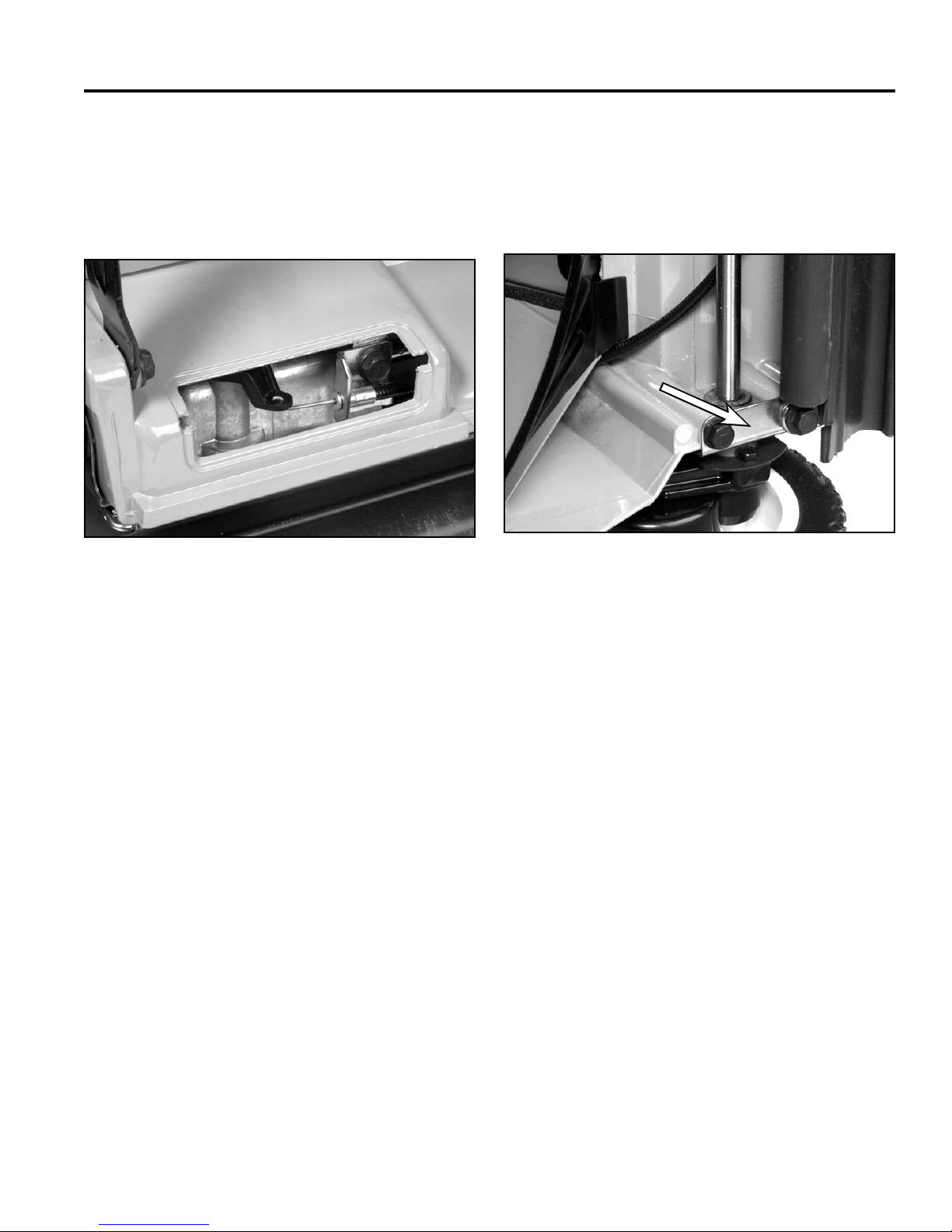
THREE SPEED TRANSMISSION
A
Special Assembly Notes for Toro Vacu
Power/Lawn-Boy Medallion
1. Slip the gear selection cable into the shift fork lever
through the bottom as shown in Figure 130.
Fig 130 3428-0123
4. Slip the two rear end cap fasteners through the
safety shield guide wires then install. Tighten all four
end cap fasteners (Fig. 131).
Note: End cap fastener torque: 225 in-lbs. (26 Nm)
A
Fig 131 3428-0122
A. End cap
2. Bring the transmission assembly into position
underneath the deck, making sure that the end
caps are on the outside of the housing. Before
securing, install the shift fork control arm onto the
shift fork and secure with the cotter pin. Place the
transmission and pivot arm assembly into the deck.
3. Loosely install the two front end cap fasteners.
5. Slip the traction belt into position on the transmission
pulley. Make sure that it does not bind on any of the
bosses.
6. Slip the end of the traction cable into the belt guide
bracket from the outside. Install the belt guide
bracket onto the top of the transmission, making
sure that the traction belt is inside the guide.
Note: Belt guide fastener torque: 130 in-lbs. (15 Nm)
7. Slip the black plastic transmission cover into place
making sure that the belt falls in the appropriate
grooves. Install the upper BBC cover with the two
fl anged head self-tapping capscrews. Make sure
that the top edge is trapped underneath the lip of the
housing.
4-11WPM Drive Systems Manual
Page 76
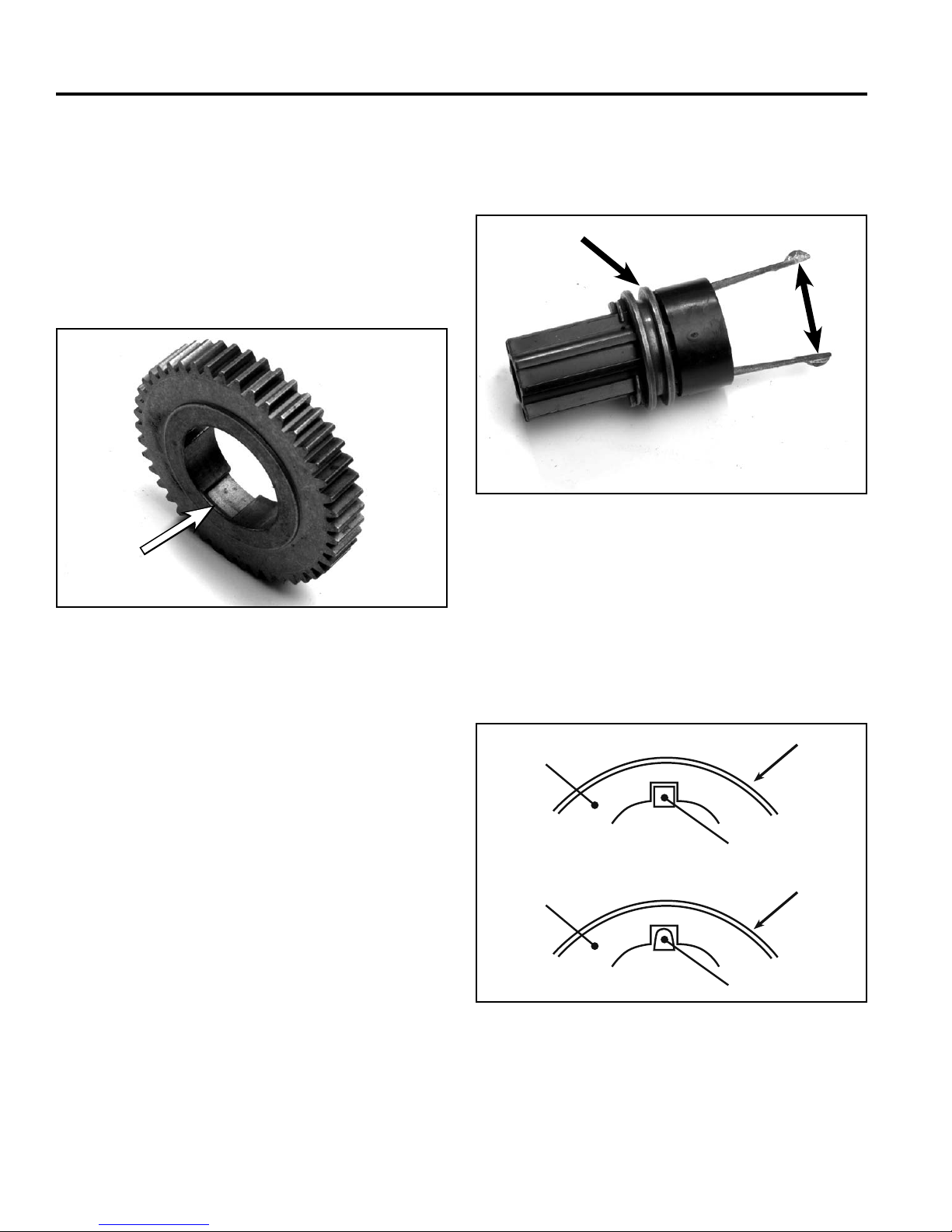
THREE SPEED TRANSMISSION
TROUBLESHOOTING TIPS - 3 SPEED
TRANSMISSION
Hard Shifting
A raised boss molded into each gear causes the leading
edge of the key to depress before it can enter the next
gear (Fig. 132).
Look at the key and the notch in the gear that it engages.
Excessive wear to the tip of the key or the notch in the
gear may be the problem (Fig. 133).
A
B
Fig 133 3428-0065
A. Shift collar B. Shift keys
Fig 132 3428-0067
The ring on the shift collar end of the key holds the drive
end of the key up. If dried grease or dirt keeps the keys
from rocking up and down, the force required to shift
gears will increase. Check the cable for free movement
where it enters the transmission. These are quick checks
and should be made before opening the transmission.
Slipping Gears
The actual gears are in constant mesh. Unless gear
teeth are broken off, they cannot slip. If the wheels lurch
forward, then pause and lurch again, along with a loud
bang each time, the keys might be slipping.
If the forces push straight on the key, it will drive the
axle. However, if due to wear the force tries to depress
the key, it can lower enough to disengage from the notch
in the gear (Fig. 134).
C
A
B
D
A
B
Fig 134 gear and key
A. Gear C. Good gear and key
B. Key D. Worn gear and key
4-12 WPM Drive Systems Manual
Page 77

WHEEL PINION CLUTCH
Worm Drive Transmission . . . . . . . . . . . . . . . . . . . . . . . .
Single Speed Spur/Bevel Gear Transmission . . . . . . . . . . . . .
Single Speed Bevel Gear Transmission . . . . . . . . . . . . . . . .
Three Speed Transmission . . . . . . . . . . . . . . . . . . . . . . .
Wheel Pinion Clutch . . . . . . . . . . . . . . . . . . . . . . . . . . .
1
2
3
4
5
Blade Brake Clutch Systems (BBC), Blade Override
System (BOS), Blade Clutch Systems (BCS) . . . . . . . . . . . . .
Handles and Control Cables . . . . . . . . . . . . . . . . . . . . . .
Self-Propel Belt Replacement . . . . . . . . . . . . . . . . . . . . . .
6
7
8
5-1WPM Drive Systems Manual
Page 78
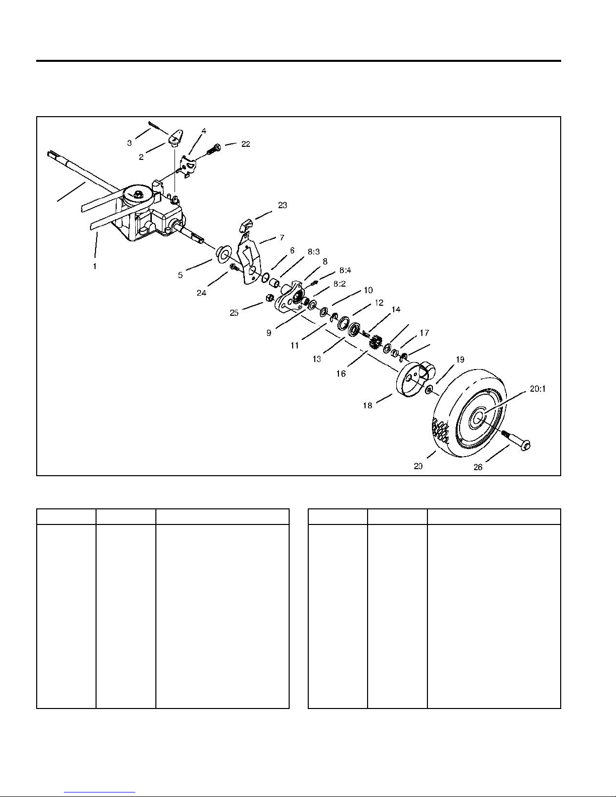
WHEEL PINION CLUTCH
GEARCASE AND WHEEL ASSEMBLY, ROCKING KEY STYLE
27
10
Ref. No. Qty Description
1
2
3
4
5
6
7
8
8:2
8:3
8:4
9
10
11
12
1
1
1
1
2
2
2
2
1
1
1
2
4
4
2
V-Belt
Lever-Shift
Pin-Cotter
Clamp-Cable
Cap-End
O-Ring
Spring Arm ASM
Pivot Arm ASM
Bushing
Bushing
Fitting-Zerk
Washer-Arm, Pivot
Washer-Thrust, Keyed
Ring-Klip
Ring-Friction
11
Fig 135 gearcase wheel assy
Ref. No. Qty Description
13
14
*15
16
17
18
19
20
20:1
22
23
24
25
26
27
2
1
1
2
2
2
2
2
2
1
2
2
2
2
1
Washer-Clutch
Key-Rocking, LH
Key-Rocking, RH
Gear-Pinion
Spring-Compression
Cover-Wheel
Spacer-Cover, Wheel
Wheel ASM
Bushing
Screw-HH
Knob-Arm
Screw-HH
Nut
Bolt-Shoulder
Output Shaft
5-2 WPM Drive Systems Manual
*Not illustrated
Page 79
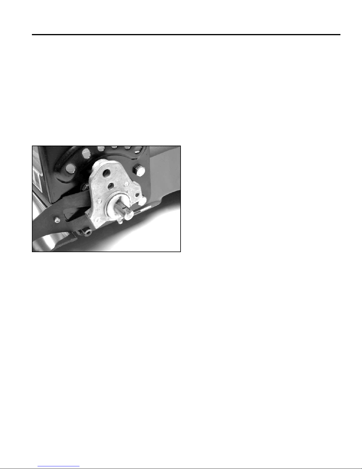
WHEEL PINION CLUTCH
Wheel Pinion Clutch
The wheel pinion clutch has a three-fold purpose. One,
when the transmission is engaged, it causes the pinions
to move with the output shaft and drives the wheels.
Two, it provides differential action to allow easy turning
and excellent maneuverability. Three it disengages the
wheel pinions from the output shaft when the operator
is not squeezing the handle. This allows the wheels
to turn backwards without turning the gears inside the
transmission and provides low pull back forces similar to
those on a hand-push version (Fig. 136).
10. Keyed Thrust Washer – internal tab fi ts in the
keyway on the output shaft. This washer rotates
with the output shaft and protects outboard clutch
components from wear.
11. Clip Ring – fi ts in a groove on the output shaft to
retain the pivot arm and spring arm. The tab at the
center of the clip is extended and fi ts in the keyway
of the output shaft to prevent rotation. If an E-clip
is substituted, premature failure of the wheel pinion
clutch system will result.
12. Friction Ring – fi ts in a circular groove in the pivot
arm and works with the clutch washer to actuate the
key. It does not rotate.
13. Clutch Washer – is affi xed to the output shaft by
means of the key so it turns with the output shaft.
It is also allowed to rotate slightly with respect to
the output shaft. This slight back and forth rotation
actuates the wheel pinion key. Friction between the
clutch washer and friction ring causes the clutch
washer to lag the output shaft slightly once it is
engaged. That slight rotation is all that is necessary
to raise the wheel pinion key and engage the pinion.
Fig 136 3428-0028
Component Defi nitions
27. Output Shaft – turns when the operator squeezes
the handle to provide power to the wheels.
8. Pivot Arm Assembly – provides support for the
output shaft with a bushing and a needle bearing. It
can be rotated in the end cap to change height-ofcut.
9. Washer Pivot Arm – fi ts in corresponding recesses
on the pivot arm to protect pivot arm from premature
wear.
14. LH Rocking Key – causes the wheel pinion to turn
with the output shaft when up. Allows the wheel
pinion to “free-wheel” when down. Clutch washer
brings key up. Wheel pinion turning forward “wipes”
key down. There is a left-hand and right-hand key.
15. RH Rocking Key – causes the wheel pinion to turn
with the output shaft when up. Allows the wheel
pinion to “free-wheel” when down. Clutch washer
brings key up. Wheel pinion turning forward “wipes”
key down. There is a left-hand and right-hand key.
16. Pinion Gear – positively engages the wheel gear
at all times. Engagement with the output shaft is
controlled by the wheel pinion key. The wheel pinion
is a powdered metal part and is symmetrical so that
it can be put on either way and still function properly.
5-3WPM Drive Systems Manual
Page 80

WHEEL PINION CLUTCH
17. Compression Spring – provides the light, constant,
inward force necessary for proper clutch washer and
friction ring engagement.
It is extremely important that the wheel pinion clutch be
maintained according to the instructions in the operator’s
manual, which is greasing every 25 hours with one or
two pumps of grease. Greasing regularly will prevent
contaminants from damaging or wearing the system.
Note: Over-greasing will also cause the system to
malfunction.
Test for Function
Function
The rocking keys provide a differential action by
engaging and disengaging each drive wheel individually.
When the drive is engaged and the axle begins to turn,
friction between the friction ring and clutch washer cause
them to rotate the tail on the key. This results in the main
part of the key engaging the teeth on the inside of the
pinion gear.
To operate this system, practice the following. Walk
along at a normal pace. When you stop walking, keep
your elbows at your sides. The mower will continue
forward for a few inches due to its momentum. As
the mower rolls away, the drive will disengage as
the personal pace/ easy stride handle extends and
disengages the transmission. From the point where the
transmission is no longer turning the axle, the mower
must roll about 1-1/2” forward. This causes the pinions to
rock the drive keys to the disengage position. At this time
the mower can be pulled backward with minimal effort.
When the drive is engaged and the axle begins to turn
the keys should re-engage.
Quick Test
If you are unsure that the keys are disengaging properly,
stop the mower, shut the engine off and push the mower
forward a few inches. If the keys disengage the system
is working correctly. Start the engine and engage the
drive, if both engage they are ok. If one or the other
do not engage or disengage properly try greasing the
pivot arm. Use #2 lithium grease and only one or two
pumps from a hand grease gun. If grease does not help
disassembly is necessary.
Should one or both wheels turn faster than the axle,
the pinion rotates and pushes the key back down into
the groove. The pinion can now roll freely over the key.
When turning the inside wheel will drive the mower. The
outside wheel must turn faster and overrides the key.
When the mower is straightened out the pinion is no
longer turning faster than the axle so the key re-engages
the pinion.
Rear Height-of-Cut and Wheel Pinion Clutch
- Disassembly
The rear height-of-cut system and the wheel pinion
clutch can be serviced with the transmission in or out of
the unit. For information on removing the transmission
from the unit, see Transmission – Removal, page 2-3,
4-5 or 4-6 depending on mower type.
1. Remove the shoulder bolt securing the wheel and
tire assembly to the pivot arm and remove the wheel
and tire assembly complete with shoulder bolt,
spacers, wheel cover, and nylon locknut.
5-4 WPM Drive Systems Manual
Page 81
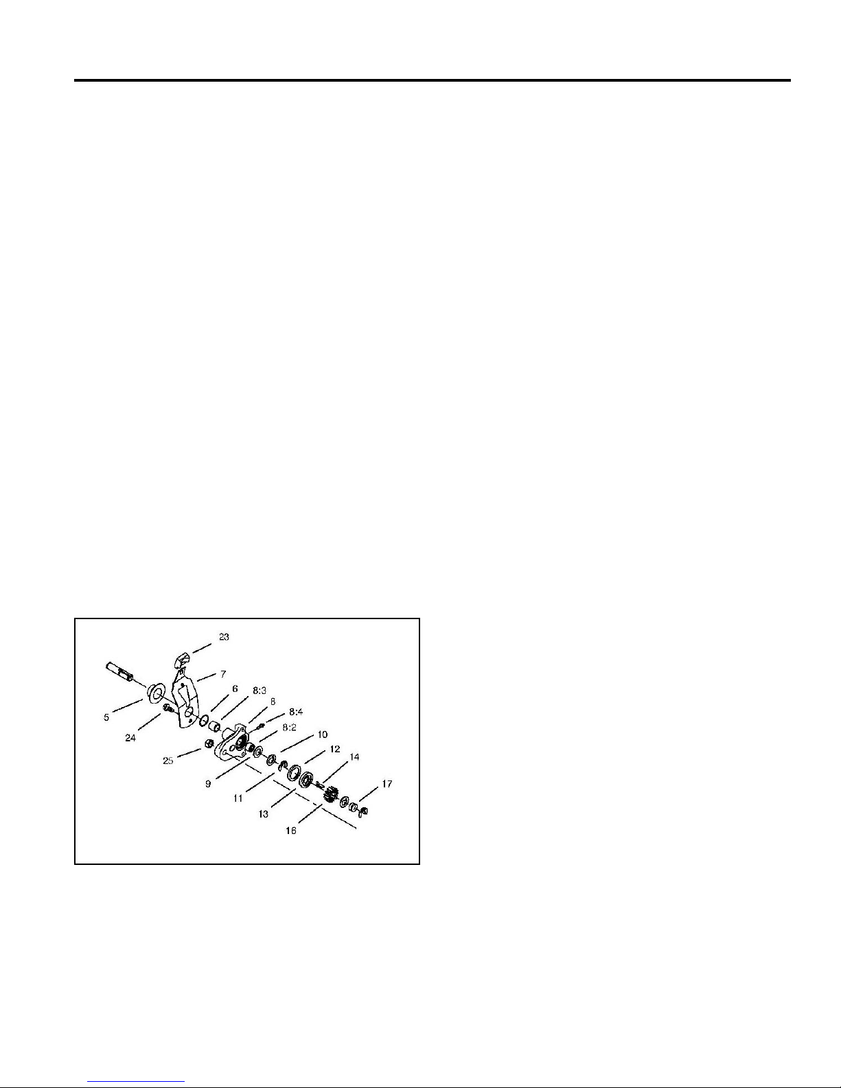
WHEEL PINION CLUTCH
2. Remove the special retaining clip at the end of the
output shaft and pull off the following six wheel
pinion clutch components:
• Spring
• Internally tabbed thrust washer
• Wheel pinion
• Wheel pinion key
• Clutch washer
• Friction ring
3. Remove the inner special retaining clip from the
output shaft and remove the following components:
• Internally tabbed thrust washer
• Externally tabbed thrust washer
• Pivot arm and spring arm assembly
• End cap (if desired)
4. Check all components at this time for damage and
wear. Pay particular attention to the grooves at
the end of the output shaft, the bearing surfaces
on the output shaft, and the wheel pinion clutch
components. Replace parts as necessary.
5. Check the innermost groove on the output shaft
which is located 2-1/4” (5.7cm) in from the end of the
shaft; make sure that the O-ring seal is present and
intact. This seal is important to keep grease in and
contaminants out. Replace it (Item 6) if necessary
(Fig. 137). Some models do not have this O-ring.
6. Press the needle bearing and the oil impregnated
bushing from the pivot arm using an arbor press.
7. Removal of the grease fi tting is not recommended
because it is pressed in. However, if damaged or
lost, we suggest tapping and installing a threaded
grease fi tting.
8. If the spring arm knob requires replacement, push in
on the detent tab, then pull the knob straight off.
Note: The detent rivet is not replaceable.
Rear Height-of-Cut and Wheel Pinion Clutch
- Assembly
1. Pack the caged needle bearing with grease, then
press into the outside of the pivot arm until it is fl ush
with the groove that houses the externally tabbed
thrust washer.
2. Press the oil impregnated bushing into the boss on
the pivot arm until it is fl ush with the face of the boss.
3. If spring arm disassembly was required, install the
knob making sure that the detent is pressed out
about .060” (1.5mm). Install the spring arm knob so
that the concave side of the knob and the convex
side of the rivet align.
Fig 137 gearcase wheel assy 2
5-5WPM Drive Systems Manual
Page 82
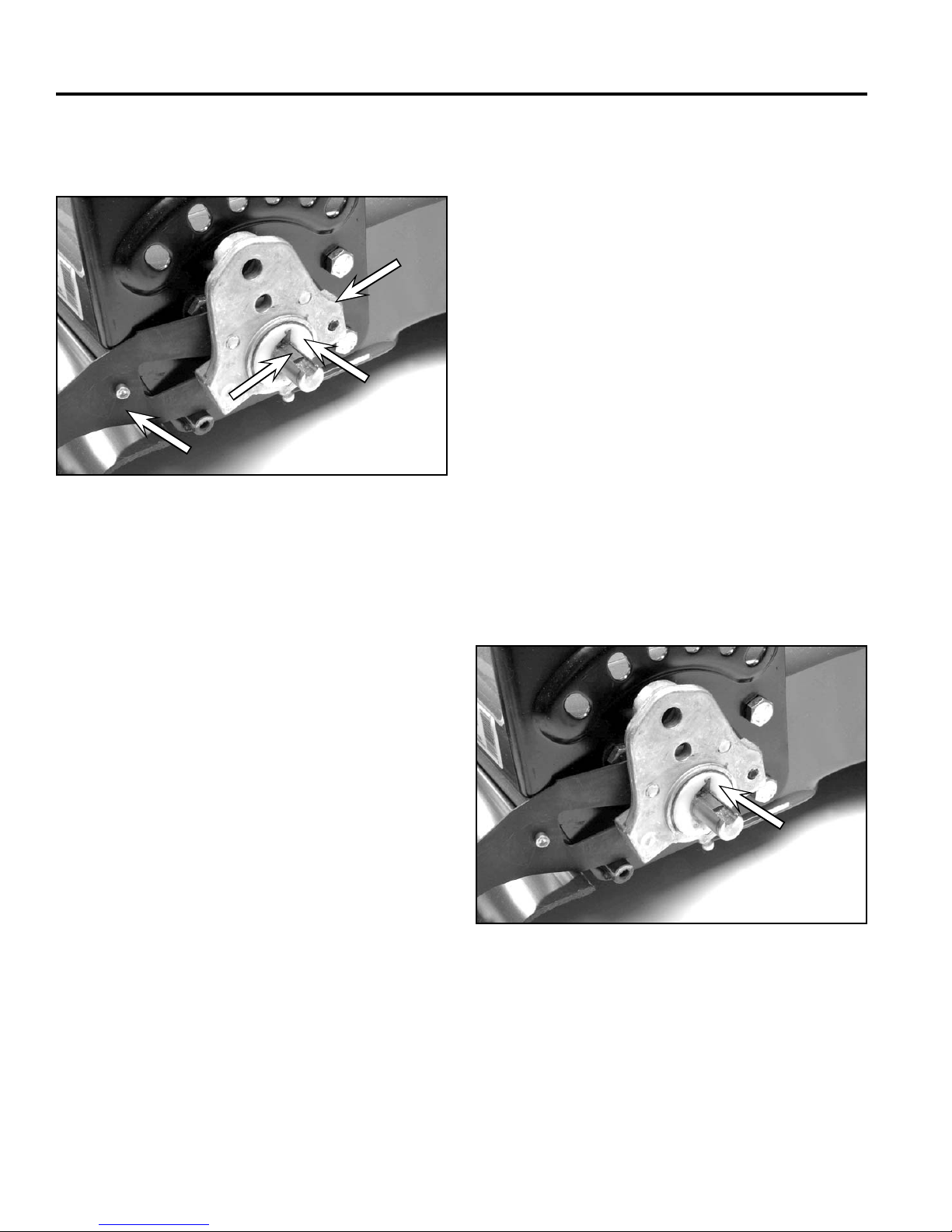
WHEEL PINION CLUTCH
B
D
C
A
4. Assemble the spring arm and pivot arm as shown in
Figure 138.
A
B
C
D
Fig 138 3428-0028
A. Pivot arm C. Key
B. Friction washer D. Spring arm
5. To increase service life, make sure all parts are
clean prior to assembly and coated with new grease.
9. Slide the externally tabbed thrust washer and the
internally tabbed thrust washer onto the output shaft.
Make sure that the tab on the internally tabbed thrust
washer enters the keyway. Secure with the special
retaining clip. Make sure that the center tab fi ts
properly into the keyway. This will prevent rotation of
the clip on the output shaft.
10. Place the friction ring into the groove on the pivot
arm, fl at side out.
11. Slide the clutch washer onto the shaft so that the
recesses for the key are facing out.
12. Place the wheel pinion key in the groove on the
output shaft with the leg toward the clutch washer.
Note: There is a left and a right wheel pinion key.
You are using the correct key if, when placed
in the groove, the top of the key is fl at and the
straight portion of the leg is perpendicular to
the shaft.
Before assembling further, rotate the clutch washer
back and forth slightly, making sure that the key
actuates properly (Fig. 139).
6. If removed, install a new O-ring in the innermost
groove 2-1/4” (5.7cm) in from the end on each
output shaft, making sure that it is fully seated in the
groove. Refer to Figure 000 (3428-0028) above. Not
all models use an O-ring.
7. Slip the end cap onto the output shaft, but do not
fasten at this time.
8. Slide the pivot arm and spring arm assembly onto
the output shaft, boss fi rst.
Note: The convex side of the spring arm rivet and
the concave side of the knob on the spring
arm should both be facing the housing.
Fig 139 3428-0028
5-6 WPM Drive Systems Manual
Page 83
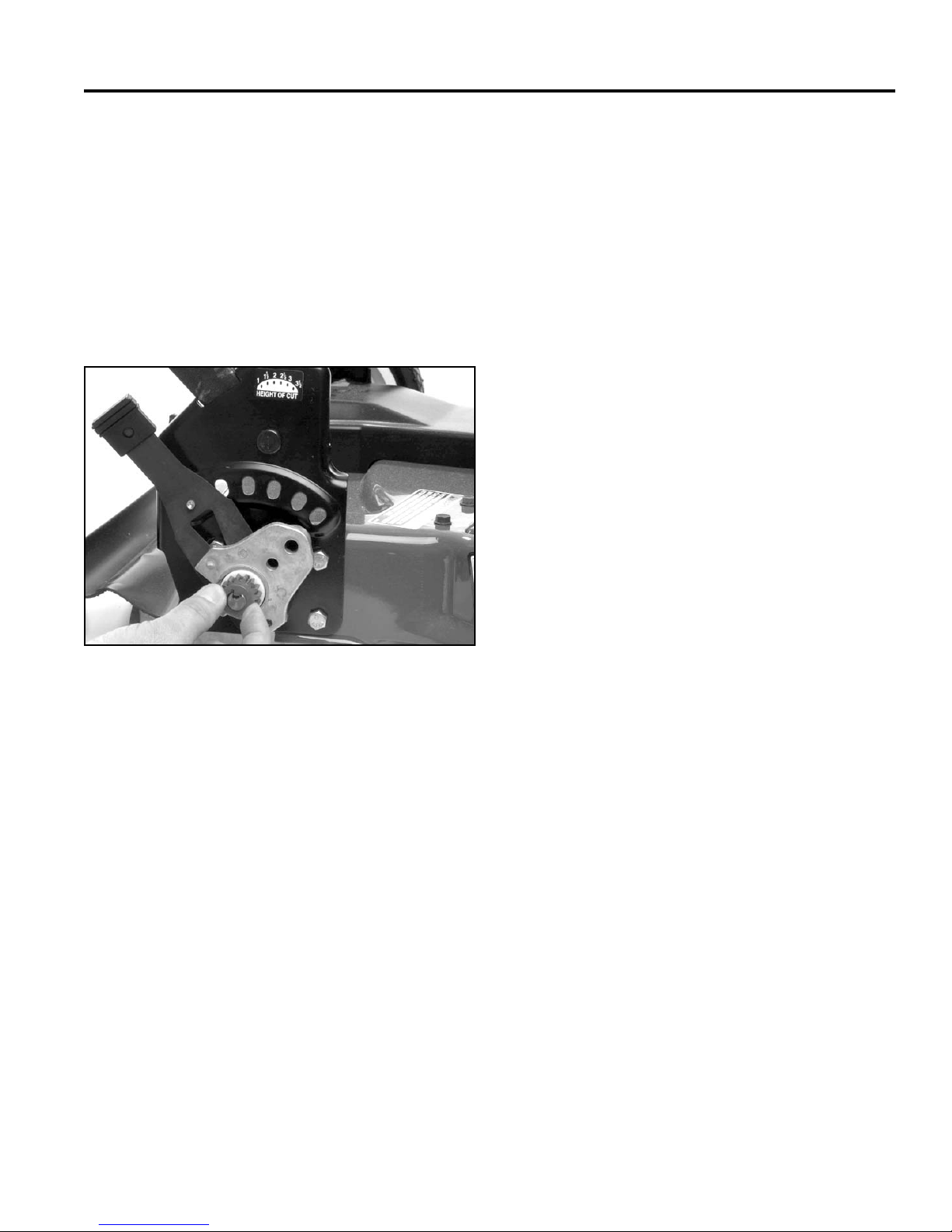
13. Place the wheel pinion onto the output shaft. It is
symmetrical and can be put on either way.
14. Install the internally tabbed thrust washer onto the
output shaft making sure that the tab enters the
keyway.
15. Slip the spring onto the end of the output shaft and
secure with the special retaining clip. Again, make
sure that the center tab fi ts properly into the keyway
to prevent rotation of the clip (Fig. 140).
WHEEL PINION CLUTCH
Fig 140 3428-0040
16. Slip the wheel, the original number of spacers, and
the wheel cover onto the shoulder bolt and secure to
the pivot arm using the nylon locknut.
17. Grease with No. 2 lithium-based grease. Use a
hand grease gun to avoid excess pressure that may
prevent the friction parts from working. As a rule, use
two pumps to ensure that you do not over-grease.
Be sure to grease after every 25 hours of use for
maximum service life.
5-7WPM Drive Systems Manual
Page 84
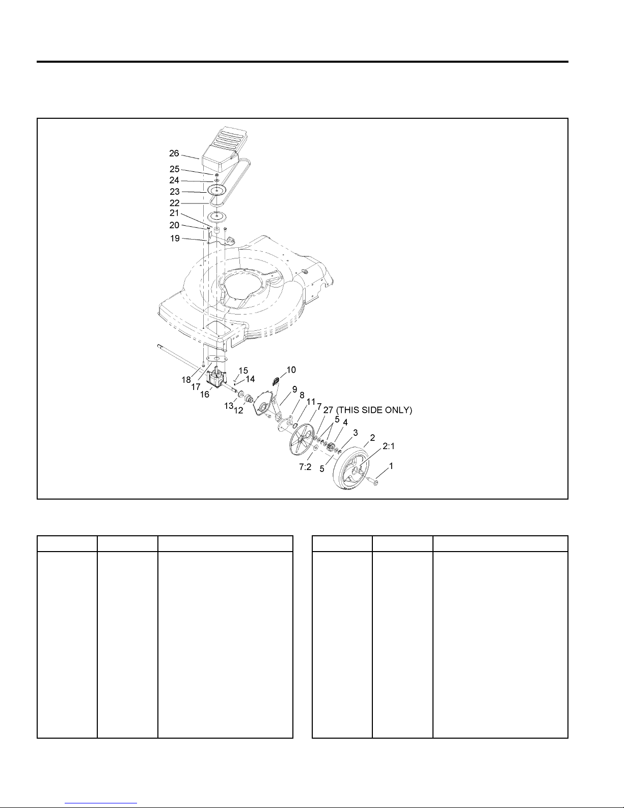
WHEEL PINION CLUTCH
GEARCASE AND WHEEL ASSEMBLY, SPRING RATCHET STYLE
3354-613 Rev A
Ref. No. Qty Description
1
2
2:1
3
4
5
7
7:1
7:2
8
9
10
11
12
13
5-8 WPM Drive Systems Manual
2
2
2
4
2
6
2
1
1
2
2
2
2
2
2
Bolt-Shoulder
Wheel Gear ASM
Bushing
Klipring-Locking
Gear-Pinion, 13T
Washer-Thrust
Cover-Wheel
Cover
Washer-Stepped
Arm-Pivot, Front
Arm-Spring
Knob-Lever, HOC
Ring-Retaining
Retainer-Bearing, HOC
Bearing-Ball
Fig 141 3354-613(5)
Ref. No. Qty Description
14
15
16
17
18
19
20
21
22
23
24
25
26
27
2
2
1
1
2
1
2
1
1
2
1
1
1
1
Spring-Compression
Key
Transmission ASM
Gasket-Gearbox
Screw-HWH
Bracket-Pivot, Fwd
Screw-HWH
Spacer
V-Belt
Pulley-Half, Front
Washer-Flat
Nut-Lock
Cover-Belt, Front
Washer
Page 85
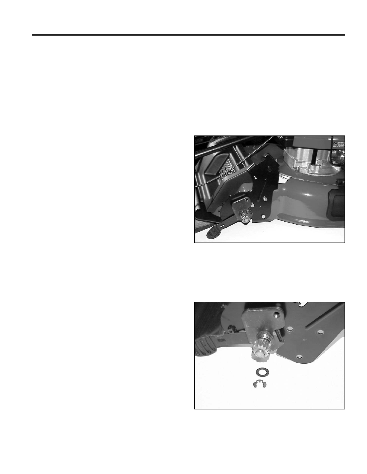
WHEEL PINION CLUTCH
Spring Ratchet Style
The Spring Ratchet type wheel clutch system has been
used on a wide variety of models. It consists of a spring
supporting a drive key which engages the pinion. When
the mower drive is engaged the axle turns the key which
is engaged with an internal tooth on the pinion. The
pinion turns the wheel gear. When the mower is pushed
or turned, the pinion must rotate faster than the axle.
As the pinion rotates it depresses the key, allowing the
differential action.
The axle drives both keys and pinions equally but they
will ratchet individually. When the mower is pulled
backwards, this type of clutch does not disengage. It will
require the axle and transmission to turn backwards. It is
critical to easy backing to make sure the self propel belt
properly disengages.
Servicing the System
The things that can impede the function are dirt, rust or
wear. The owner’s manual requires that ordinary engine
oil be added to each side of the pinion periodically.
This is to keep the anti seize from drying up. If that is
not done, it will be necessary to remove the pinion,
key and spring to clean and re-lubricate with anti-seize
compound.
WHEEL PINION SERVICE
The steps to service the wheel pinions are the same for
both front and rear wheel drive models.
1. Raise the mower until the wheel is off the ground.
Support with a block.
2. Remove the wheel bolt, wheel and wheel cover (Fig.
142).
Fig 142 MVC-739
On the left side there will be two keyed thrust washers
and one regular thrust washer. Clean the end of the axle,
keyway, and the parts removed. Inspect the key; if worn,
replace. Make sure the thrust washers have the key tab
on them. If the tab is broken, the pinion will tend to push
the retaining rings out of their grooves.
Lubricate the key, spring, and axle with anti-seize
compound and reassemble. Note the pinion has the
letter “R” stamped on one side and “L” on the other. If
you are on the right side of the mower, the letter “R”
should face you when you install the pinion. The letter
“L” should be visible on the left side of the mower.
3. Remove the retaining ring and thrust washer (Fig.
143).
Fig 143 MVC-746
5-9WPM Drive Systems Manual
Page 86
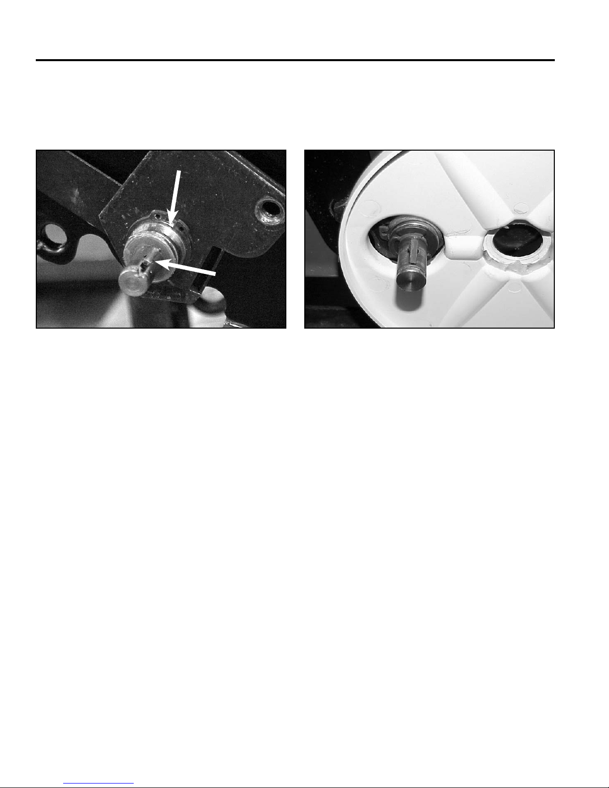
WHEEL PINION CLUTCH
4. Slide the wheel pinion off the axle.
Note: There is a spring-loaded key under the pinion
(Fig. 144).
A
B
Fig 144 MVC-850
A. Retaining ring and B. Key
thrust washer
Reassemble in reverse order:
1. Install one thrust washer, then the fi rst retaining ring
with the sharp edge facing the chassis (Fig. 145).
Fig 145 MVC-472
2. Lubricate with anti-seize and assemble in the
original order.
5. Behind the pinion should be another thrust washer
and retaining ring (Fig. 000). (MVC-850)
5-10 WPM Drive Systems Manual
Page 87

BBC / BOS / BCS
Worm Drive Transmission . . . . . . . . . . . . . . . . . . . . . . . .
Single Speed Spur/Bevel Gear Transmission . . . . . . . . . . . . .
Single Speed Bevel Gear Transmission . . . . . . . . . . . . . . . .
Three Speed Transmission . . . . . . . . . . . . . . . . . . . . . . .
Wheel Pinion Clutch . . . . . . . . . . . . . . . . . . . . . . . . . . .
1
2
3
4
5
Blade Brake Clutch Systems (BBC), Blade Override
System (BOS), Blade Clutch Systems (BCS) . . . . . . . . . . . . .
Handles and Control Cables . . . . . . . . . . . . . . . . . . . . . .
Self-Propel Belt Replacement . . . . . . . . . . . . . . . . . . . . . .
6
7
8
6-1WPM Drive Systems Manual
Page 88
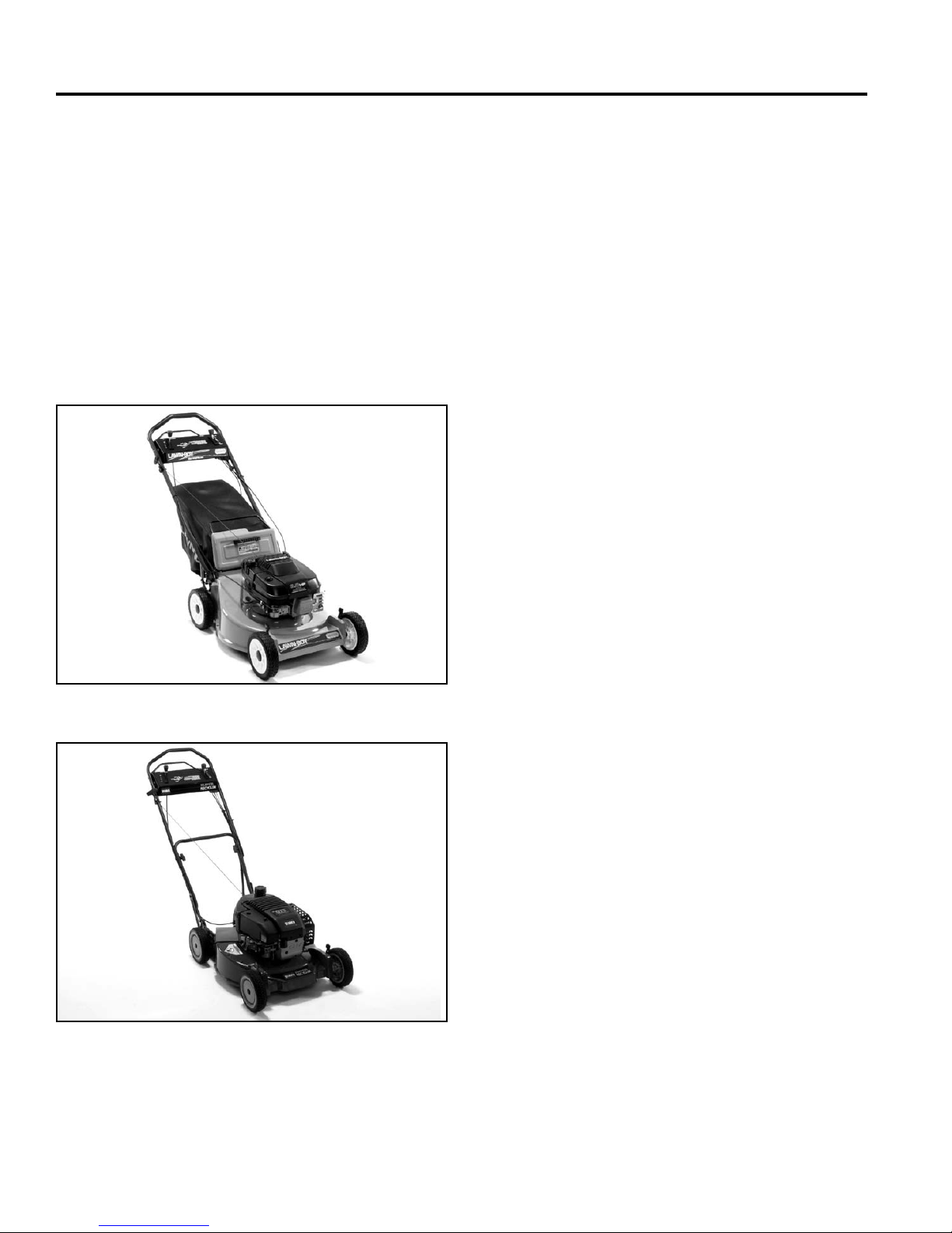
BBC / BOS / BCS
BLADE BRAKE CLUTCH SYSTEM
(BBC)
Description
There are two basic blade clutching system designs.
The fi rst is commonly referred to as the BBC or Blade
Brake Clutch. It has two versions which have been used
on many Toro models as well as Lawn-Boy Medallion
mowers. The second design was introduced in 2005 and
is used on Toro (Blade Override System) and Lawn-Boy
(Blade Clutch System) (Fig. 146 and Fig. 147).
The blade clutch system offers the customer
convenience to stop the blade while allowing the engine
to continue to run.
Before troubleshooting the BBC deck mechanism, be
sure that it is adjusted properly. Refer to the BBC cable
adjustment section for proper adjustments.
BBC Clutch Operation
The clutch operates by using a fl ywheel which turns with
the engine crankshaft and a brake drum and blade that
are free to turn separately from the fl ywheel. The two
are connected by tensioning a drive belt between the
fl ywheel and brake drum. The combination idler arm and
brake controls the belt. When the control is engaged,
the idler with the brake pad backs away from the brake
drum and tightens the belt. When the control is released,
a spring causes the idler to pivot towards the brake drum
releasing the belt and engaging the brake. This stops the
blade but allows the fl ywheel and crankshaft to continue
to turn.
Fig 146 3428-0001
Fig 147 3428-0004
BBC Control Box Operation
The BBC control mechanism’s purpose is to actuate
the deck mechanism. It does this by tensioning and
loosening the BBC cable. The control mechanism meets
the federal government’s “2-step” blade engagement
procedure. The traction drive can also be integrated with
this control system.
6-2 WPM Drive Systems Manual
Page 89
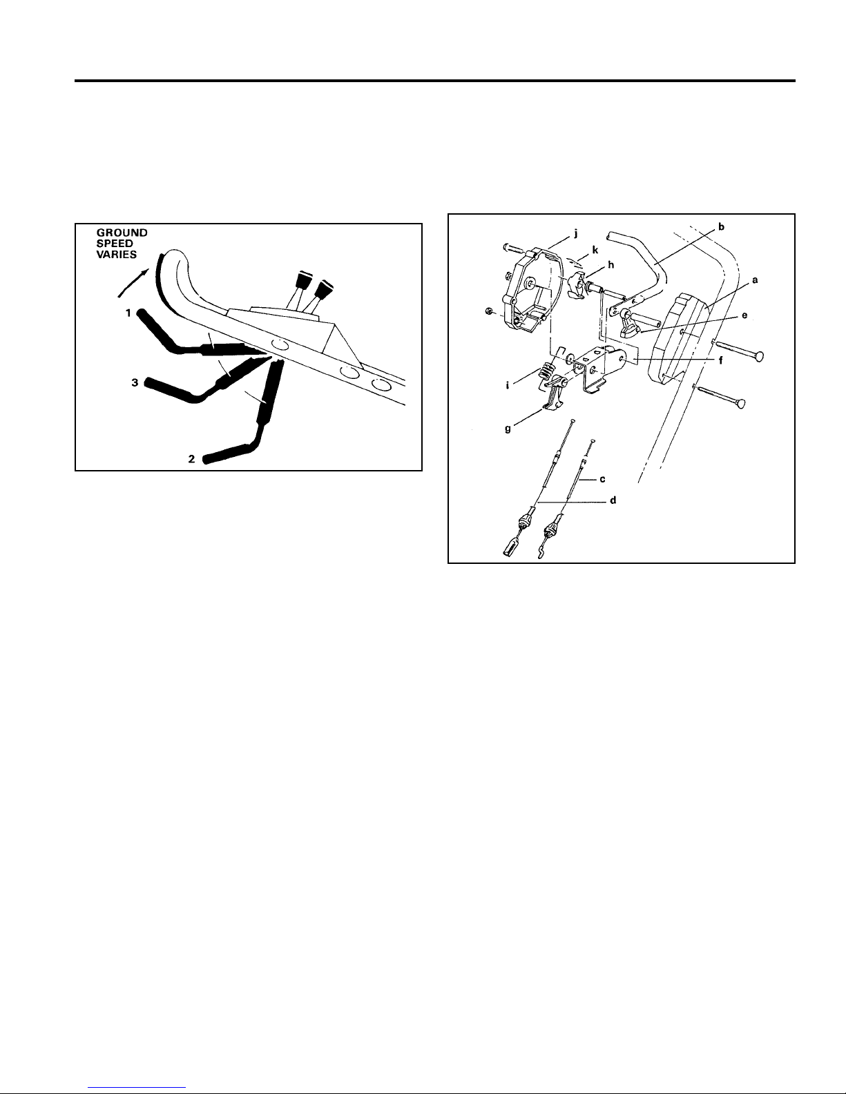
BBC / BOS / BCS
The normal or “at rest” position of the control bar is
indicated by the number 1 in the Figure 148. In order
to engage the blade, the operator must fi rst “cock” the
control bar down to position 2, then raise the control bar
to position 3.
Fig 148 fi g 27
Handle Controls
The control box components and their functions (Fig.
149) are described below.
Notice that position 3 is approximately 5” (12cm) below
the handle. This distance between position 3 and the
handle is reserved for engagement of the transmission
on those models equipped with self-propel. On units
without self-propel, the control bar can be lifted to the
handle without affecting operation of the BBC system.
After engagement of the blade, release of the control bar
disengages the blade and, on self-propel models, the
transmission. By gradually releasing the control bar, the
operator can regulate the ground speed of self-propel
models without disengaging the blade.
Fig 149 fi g. 28
a. Left Control Housing: serves as the cover for the
BBC control mechanism. It also houses the end of
traction and BBC cables.
b. Control Bar: pivots on upper shoulder bolt. Transfers
operator inputs to control box components.
c. Traction Cable: engages the transmission by trans-
ferring inputs from the control box. The transmission
is engaged when the cable is tightened; disengaged
when the cable is loosened.
d. BBC Cable: transfers inputs from the control box to
the BBC deck mechanism.
6-3WPM Drive Systems Manual
Page 90
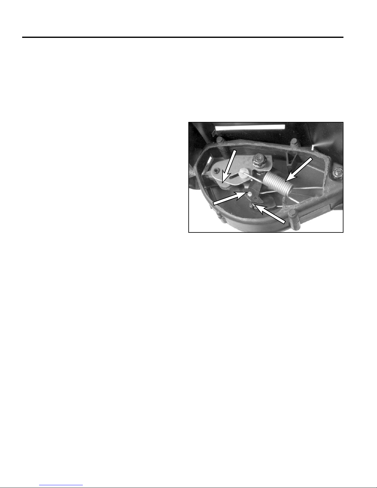
BBC / BOS / BCS
A
B
C
D
e. Traction Lever: provides input to the traction cable
since the end of the traction cable is retained in it.
It also pivots on the upper shoulder bolt when the
control bar is moved.
f. Rocker Arm: pivots on the upper carriage bolt. It is
affi xed solidly to the control arm by means of the roll
pin. It houses both the control hook and cable lever.
It also provides slot and stop for the buckling spring.
g. BBC Cable Lever: controls tensioning and loosening
of the BBC cable since the end of the BBC cable
is retained by it. Pivots freely on the upper carriage
bolt. Movement is controlled by the control hook.
h. Control Hook and Spring: pivots on the roll pin and
is spring-loaded in the counterclockwise direction by
the torsion spring. The control hook “grabs” the cable
lever when the control bar is cocked and releases
the cable lever when the control bar is dropped.
i. Buckling Spring: sole purpose is to hold the control
bar in the middle position when at rest. The spring is
fl exed or “buckled” when the control bar is operated.
It rides in a slot on the rocker arm to prevent it from
applying force to the control bar when the control bar
is at its lowest or uppermost positions.
j. Right Control Housing: serves as the other half of
the control box cover. Houses the leaf spring.
These components interact to provide control to the BBC
deck mechanism. Notice in Figure 150 the position of
the traction cable lever and the BBC cable lever. This is
the “at rest” position; both the BBC and the transmission
are disengaged. When the control bar is in this position,
it is the buckling spring that supports it. Notice that the
buckling spring is not fl exed and is at the left end of the
slot in the rocker arm.
A
D
B
C
Fig 150 3428-0278
A. Control hook C. Traction cable lever
B. BBC cable lever D. Buckling spring
k. Leaf Spring: releases the control hook as the
control bar drops to “at rest” position. Because of its
orientation, it allows the control hook to slip by as the
control bar is raised.
6-4 WPM Drive Systems Manual
Page 91
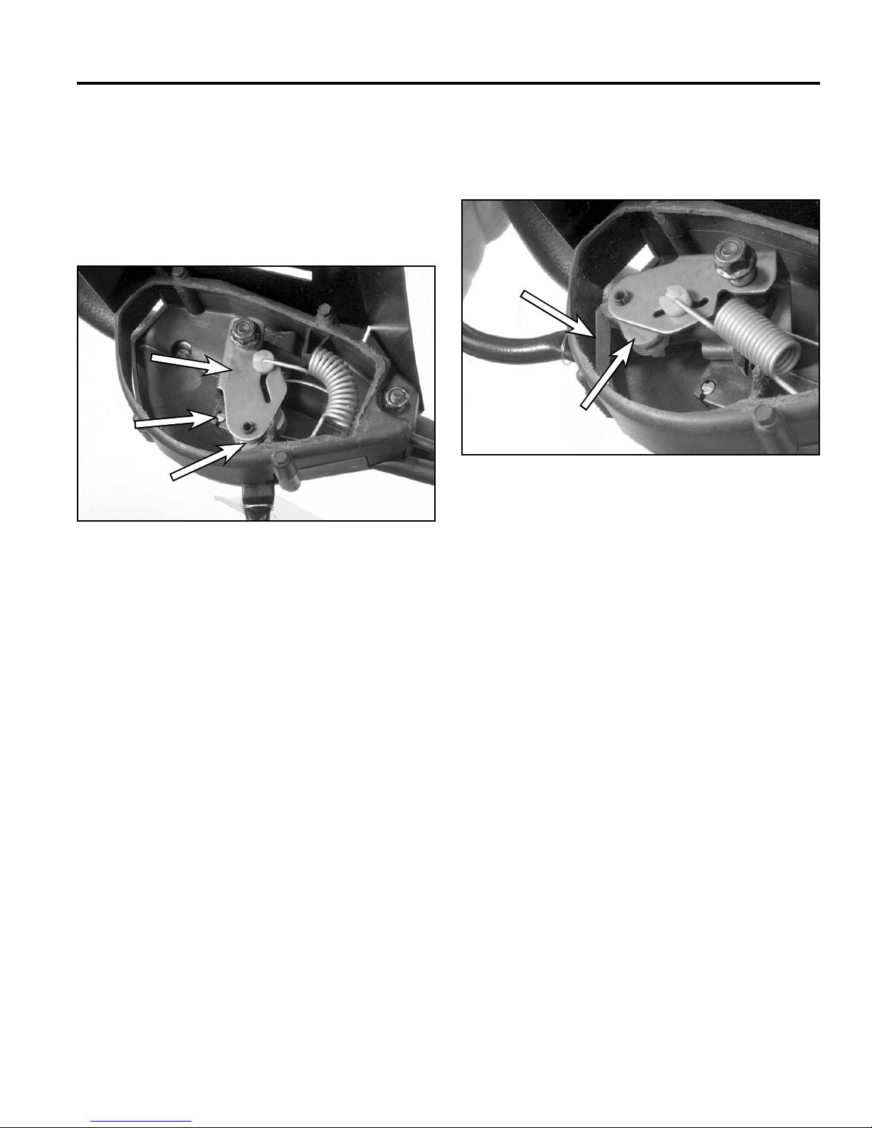
BBC / BOS / BCS
A
B
C
A
B
When the control bar is cocked to its lowest position as
in Figure 151. The buckling spring is fl exed and moved
to the right end of the rocker arm slot. Another event
takes place inside the rocker arm: The spring-loaded
control hook slides over the cable lever and grasps it so
that when the lever is raised, the BBC cable will come
with it.
A
B
C
Fig 151 3428-0286
When the control bar is raised to a point 5” (12.7cm)
below the handle, the BBC cable has been tightened
enough to engage the blade (Fig. 152).
A
B
Fig 152 3428-0289
A. Leaf spring B. Control hook
A. Rocker arm C. Control hook
B. BBC cable lever
Raising the control bar straightens the buckling spring.
Also important is the function of the leaf spring. As the
control bar is raised, the left tip of the control hook slips
by the leaf spring without causing release of the cable
lever.
Continuing to raise the control bar causes the traction
lever to move and the traction cable engages the
transmission.
6-5WPM Drive Systems Manual
Page 92
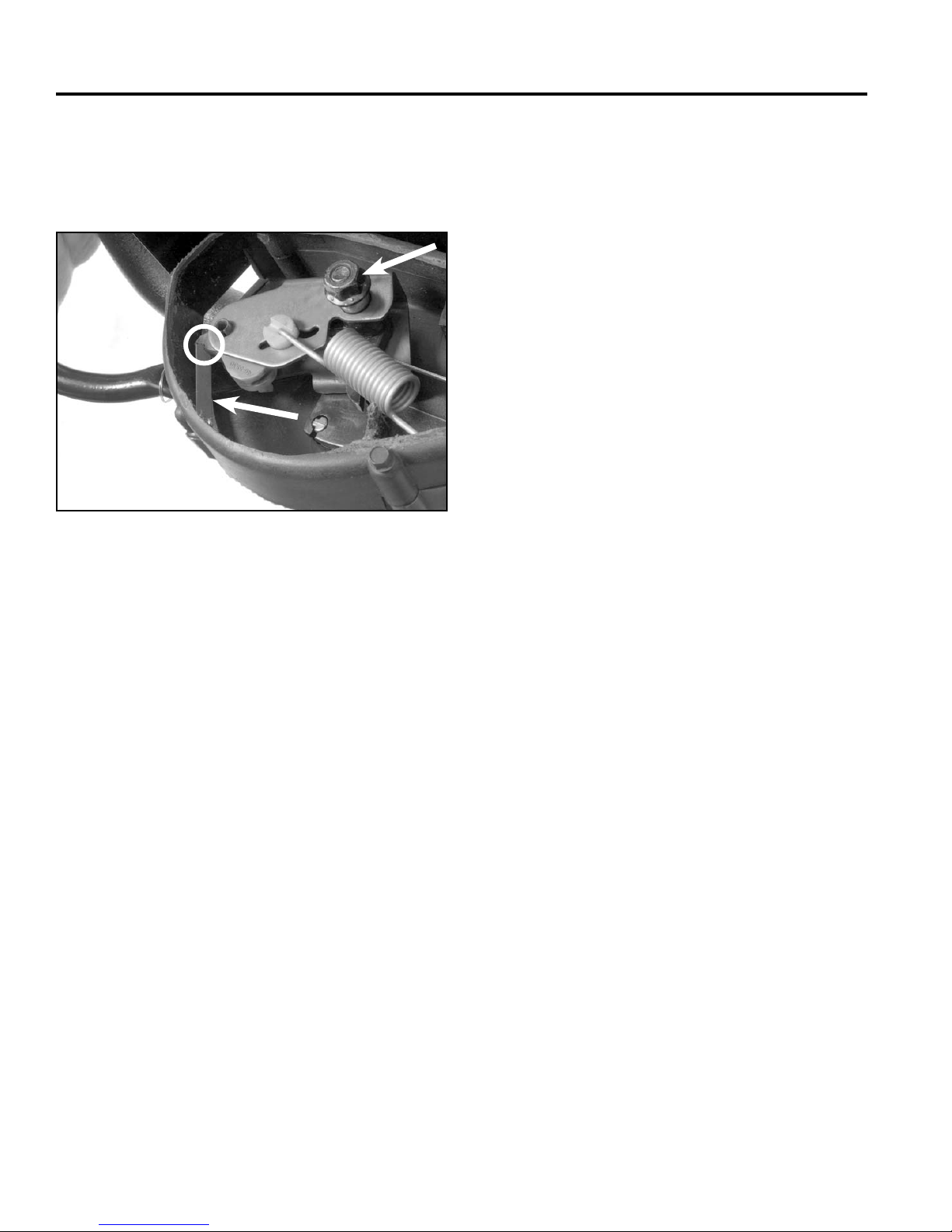
BBC / BOS / BCS
A
B
C
When the control bar is released, the tip of the control
hook catches on the leaf spring causing it to rotate. This
releases the BBC cable lever, thereby causing the BBC
to declutch and apply the blade brake (Fig. 153).
C
A
B
Fig 153 3428-0290
A. Contact point C. Flange nut
B. Leaf spring
Control Box Disassembly
NOTE: When servicing the BBC control box, be careful
not to disassemble the unit any further than necessary
as it will then become diffi cult to trouble shoot. Instead,
remove the right housing half, then operate the control
box while watching for proper function of internal
components. See Step 5 below for more information.
2. Bend the locking tab securing the throttle control to
the control panel, then tap the throttle control out
using a rubber mallet.
3. Remove the 3 fl anged head screws retaining the 2
control box halves.
4. Carefully remove the 2 fl ange nuts retaining the
control box to the handle and remove the right
control box half. Be careful not to dislodge any
internal components.
5. Reinstall the fl ange nuts to help hold things together.
Determine if any of the components inside the
control box are malfunctioning.
CAUTION! Wear gloves and eye protection when
operating an open control box as the buckling
spring could fl y out.
Note: The cable ends and end of the spring are not
retained once the right cover is removed. Be
sure to use one of the two methods below to
retain them.
The fi rst and quickest method is to manually hold the
ends of the cable and the end of the buckling spring
while operating the control bar. However, with the
right case half removed, the leaf spring is no longer
in place and you will not be able to observe release
of the BBC cable lever.
1. Place a piece of duct tape over the heads of the
carriage bolts passing through the handle and the
BBC control box. This will prevent them from falling
out later during troubleshooting.
6-6 WPM Drive Systems Manual
Page 93
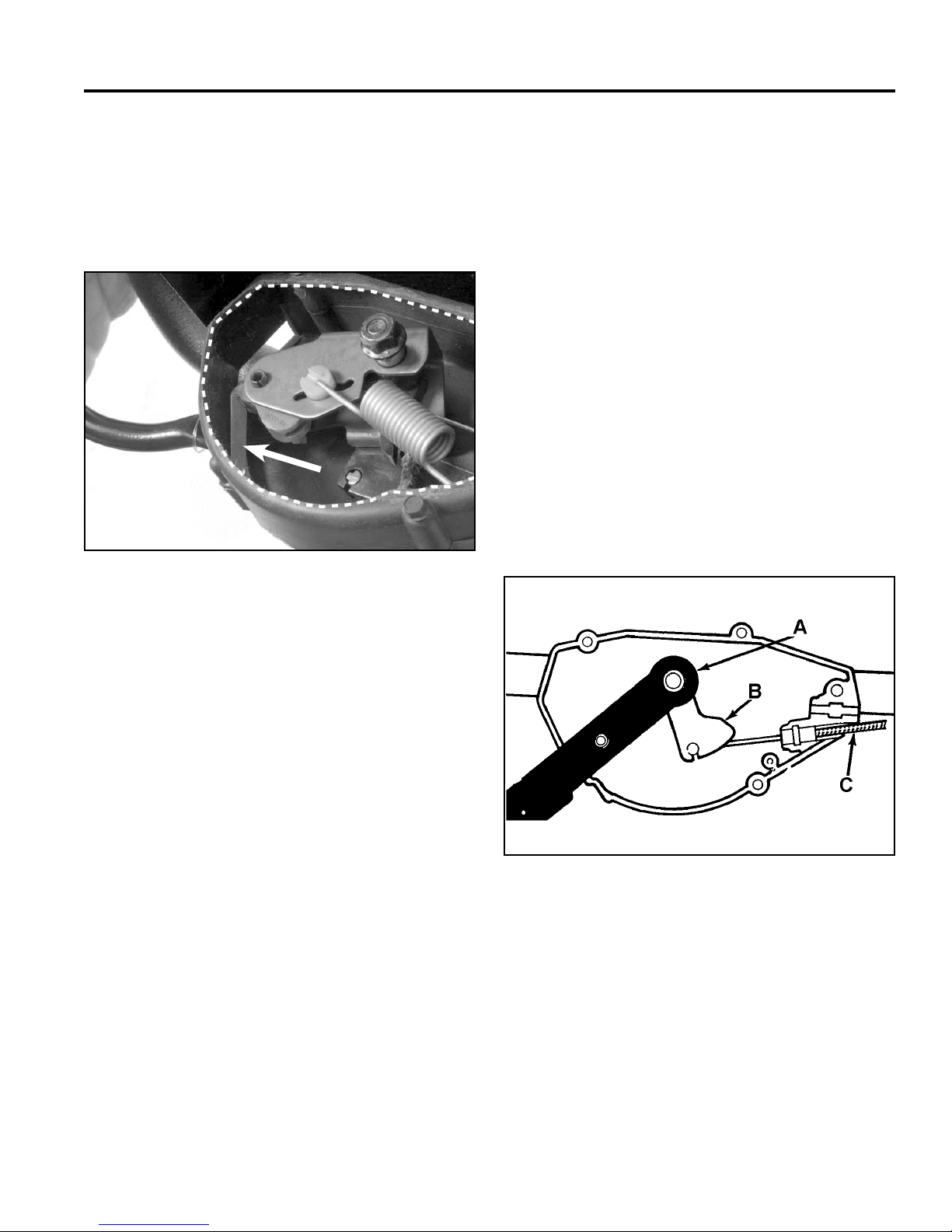
BBC / BOS / BCS
A
A better method is to make a special cut-away
version of the right control box housing half as
shown in Figure 154. When this cut-away version
is installed, all components will function normally.
Notice the cut-away cover and how it houses the leaf
spring. This will aid in diagnosis.
A
Fig 154 3428-0289b
12. Pull the tape from the outside of the handle. Remove
the upper carriage bolt along with the cable lever
and spacer.
13. Remove the lower carriage bolt and remove the left
control housing.
14. Inspect all parts for wear and/or damage and replace
as required.
Control Box Assembly
1. Slip the lower carriage bolt through the handle, then
slide the left control housing onto it.
2. Slip the end of the traction cable into the traction
lever. Place the control housing, traction lever, and
the control bar into position as shown in Figure 155.
Once in position, slide the carriage bolt through all
three components.
A. Leaf spring
6. If further disassembly is required, remove the
buckling spring and washer from the rocker arm
assembly.
7. Remove the BBC cable from the BBC cable lever
and the left-hand control box half.
8. Remove the rocker arm as an assembly, complete
with cable lever and control hook.
9. Remove the cable lever from the rocker arm
assembly.
10. Press the roll pin from the rocker arm and remove
the control hook and torsion spring.
11. Remove the traction cable from the traction lever
and the left-hand control housing.
Fig 155 fi g 34
A. Leaf spring C. Traction cable
B. Traction lever
6-7WPM Drive Systems Manual
Page 94
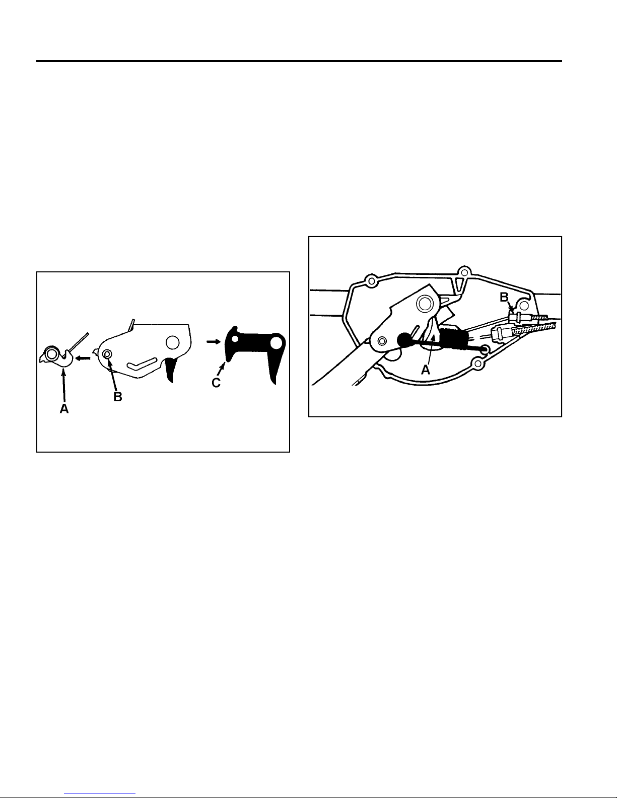
BBC / BOS / BCS
3. Place a piece of duct tape over the heads of the
carriage bolts that slide through the handle and the
left control box housing. This will aid in assembly.
4. Slide the sleeve onto the upper carriage bolt making
sure that it passes through the control bar, traction
lever, and left control housing.
5. Position the control hook and torsion spring in the
rocker arm as shown in Figure 156. Secure with the
roll pin making sure that the roll pin is fl ush with the
side indicated in the fi gure. Loosely install the BBC
cable lever as indicated. When correctly installed,
the control hook and the cable lever will be engaged.
6. Slide the rocker arm assembly over the upper
carriage bolt and sleeve making sure that the sleeve
passes through the cable lever. Also make sure that
the roll pin passes through the hole in the control
bar.
7. Release the BBC cable lever from the control hood
and install the BBC cable into the cable lever (Fig.
157).
Note: The BBC cable lever is behind the spring.
Fig 156 fi g 35
A. Control hook C. Cable lever
B. Roll pin fl ush with
this side
Fig 157 fi g 3 6
A. BBC cable lever B. BBC cable
6-8 WPM Drive Systems Manual
Page 95
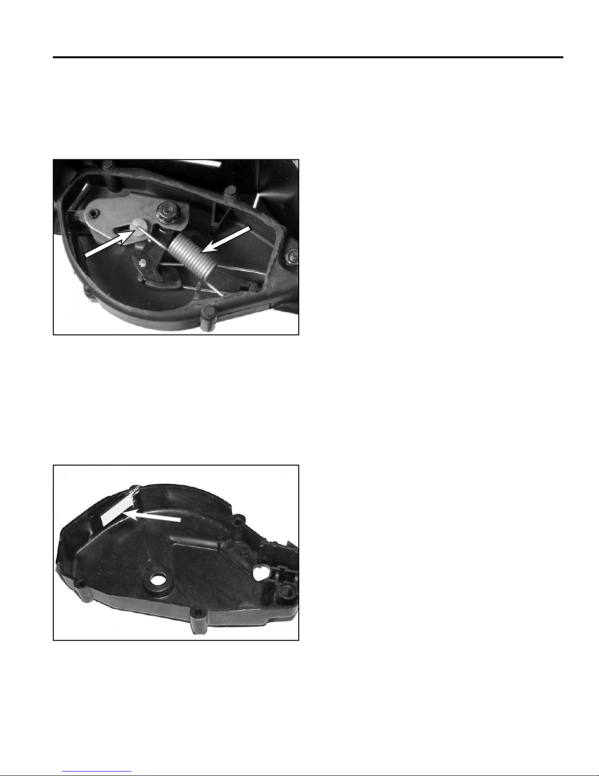
BBC / BOS / BCS
A
B
8. Slip the white nylon washer onto the J end of the
buckling spring. The slotted side of the washer
should face away from the end of the spring. Slip
the spring into position in the rocker arm and the left
control housing as shown in Figure 158.
B
A
Fig 158 3428-0281
A. Nylon washer B. Buckling spring
10. Before installing the right control housing, check
to make sure that both cable sheath ends are fully
seated in their slots in the left housing. Also make
sure that the sleeve passes through all components
including the left control housing. Finally, make sure
that the roll pin passes through the rocker arm and
control bar.
Install the right control housing and secure with the 2
nylon locknuts or 1 locknut and 1 fl ange nut.
11. Install the 3 fl anged head screws that retain the two
control box halves.
12. Check for proper operation of the entire BBC
system. Correct as required.
13. Bend the throttle control locking tab forward to
provide positive lock with the throttle control and
install the throttle control.
14. Adjust the BBC cable and traction cables as needed.
See page 7-16.
9. Assemble the right control housing by installing the
leaf spring and pin to retain the leaf spring (Fig.
159).
A
Fig 159 MVC-488
A. Leaf spring
6-9WPM Drive Systems Manual
Page 96
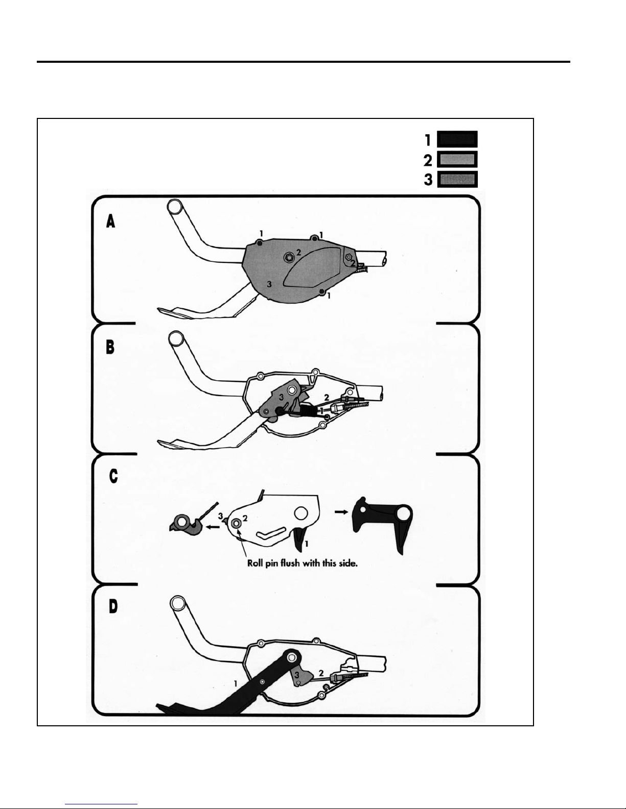
BBC / BOS / BCS
TORO BBC SERVICE GUIDE
Disassembly Sequence
6-10 WPM Drive Systems Manual
Fig 160 bbc scan
Page 97
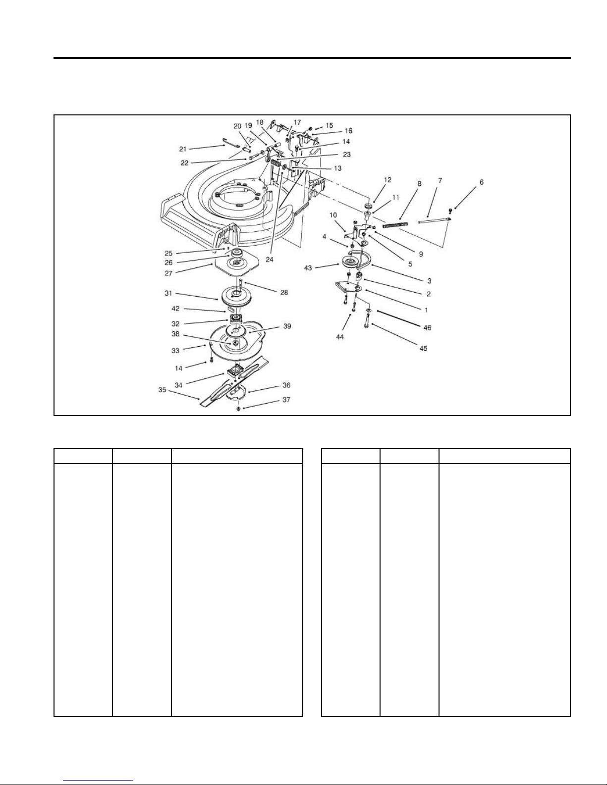
BBC / BOS / BCS
BLADE BRAKE CLUTCH ASSEMBLY (Toro Vacu Power/Lawn-Boy Medallion BBC)
Ref. No. Qty Description
1
2
3
4
5
6
7
8
9
10
11
12
13
14
15
16
17
18
19
20
21
1
1
1
2
2
1
1
1
1
1
1
1
1
5
1
1
2
1
1
1
1
Brake Shoe
Plate Hub
V Belt
Pulley Hub
Lock Nut
Spring Rod
Shoulder Bolt
Compression Spring
Flange Bushing
Lever Wa
Bushing
Ring Seal
HWH Screw
TAP Screw
Flange Nut
Cable Bracket Support
Flat Washer
Bellcrank Bushing
Crank
Spring Pin
Control Link
Fig 161 bladebrakeclutchassy
Ref. No. Qty Description
22
23
24
25
26
27
28
31
32
33
34
35
36
37
38
39
42
43
44
45
46
1
1
1
1
1
1
2
1
1
1
1
1
1
2
1
1
2
1
2
1
1
HH Screw
Compression Spring
Spring Retainer
Woodruff Key
Driver Pulley
BBC Flywheel
Blade Bolt
Brake Drum
Hub ASM
BBC Shield
Blade Spacer
21” Blade
Anti Scalp Cup
Lock Nut
Lock Nut
BBC Screen
Vibration Damper
Idler Pulley
HH Screw
Thd Forming Screw
Flat Washer
6-11WPM Drive Systems Manual
Page 98
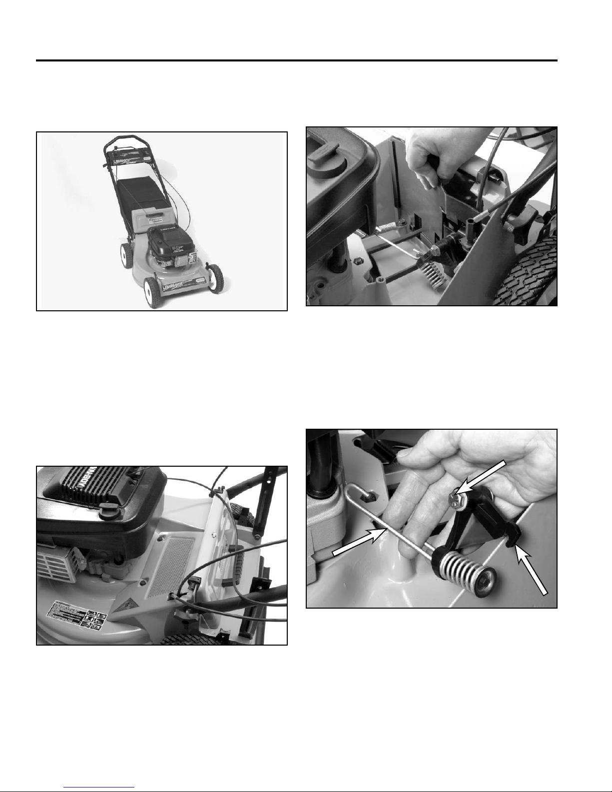
BBC / BOS / BCS
A
B
C
TORO VACU POWER/LAWN-BOY
MEDALLION BBC
Fig 162 DSC-068a
Bellcrank System Disassembly (Toro Vacu
Power/Lawn-Boy Medallion)
1. Remove the fl anged head self-tapping capscrews
securing the upper BBC cover to the housing and
remove the upper BBC cover (Fig. 163).
2. Pull the black plastic transmission cover up to
remove it from the housing (Fig. 164).
Fig 164 3428-0082
3. Remove the shoulder bolt and fl anged nut securing
the bellcrank to the control cable bracket. Once
loose, remove the bellcrank assembly complete with
control link from the unit (Fig. 165).
Fig 163 3428-0079
B
A
C
Fig 165 3428-0090
A. Control link C. Bellcrank
B. Shoulder bolt
6-12 WPM Drive Systems Manual
Page 99
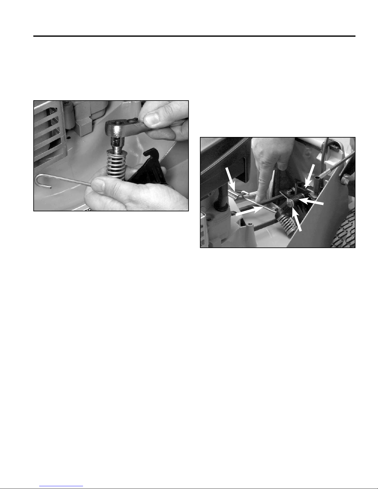
BBC / BOS / BCS
A
B
C
D
E
4. Remove the bushing from inside the bellcrank.
5. Using the control link to hold the control pin, remove
the fl anged head screw from the control pin (Fig.
166).
Fig 166 3428-0093
2. Place the spring onto the control pin. Place the
spring retainer onto the spring and insert the screw
into the control pin. Using the control link to prevent
rotation of the control pin, tighten the fl anged head
screw until the retainer bottoms out on the control
pin (Fig. 166).
3. Note the orientation of the control link in Figure
167. Make sure that it is installed correctly into the
bellcrank.
E
A
B
D
CAUTION! Always wear safety goggles and
gloves when disassembling items under spring
tension or compression.
6. Remove the control link from the control pin.
7. Inspect all parts for wear and damage and replace
as necessary.
Bellcrank System Assembly (Toro Vacu
Power/Lawn-Boy Medallion)
1. Insert the control pin into the recessed area on the
bellcrank.
C
Fig 167 3428-0088
A. Brake plate lever D. Bellcrank
B. Control link E. Cable bracket support
C. Shoulder bolt
4. Slide a fl at washer and a bushing onto the shoulder
bolt and slide into the front side of the bellcrank
as shown in Figure 000. (3428-0088) Complete
reassembly of the bell crank system by sliding
another fl at washer onto the carriage bolt.
Note: Lubrication of the bushing is not
recommended.
6-13WPM Drive Systems Manual
Page 100
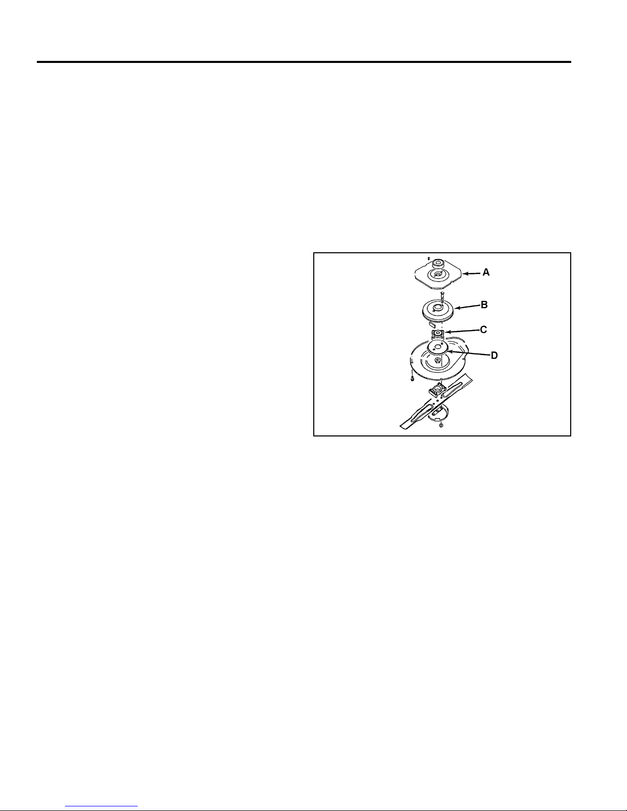
BBC / BOS / BCS
5. Hook the end of the control link into the brake plate
lever, then slip the BBC control cable onto the
bellcrank. Finally, slip the shoulder bolt through the
hole in the cable bracket support and secure with the
fl anged nut.
Note: The serrations in the fl anged nut must fully
seat on the control cable bracket.
6. Check the adjustment of the BBC cable as described
under “BBC Cable Removal (Recycler/Rear
Bagger)” on page 6-19.
7. Slide the black plastic transmission cover into place
making sure that the belt slides into the grooves
provided. Some contact between the belt and the
cover may be evident.
Note: It may be necessary to push the transmission
back slightly to get the transmission cover to
slide in completely.
8. Place the upper BBC cover into position on the
housing and secure with the two self-tapping fl anged
head capscrews.
BBC Cover and Screen:
The BBC cover and screen are two important components that keep dirt and debris out of the BBC
mechanism. The screen (Fig. 168) is installed, sharp
edge down, to allow air to be drawn in through the
screen panel on top of the deck and down underneath
the deck. This venting improves the airfl ow underneath
the deck thereby improving quality of cut and bagging
performance. Be sure to clean the screen on occasion,
especially if quality of cut or bagging performance has
degraded.
9. Check for proper operation of all controls, especially
the BBC, and adjust as necessary.
Note: The spring length on the bellcrank assembly
is the primary indicator of proper BBC
adjustment. It should measure 1” (25mm) with
the blade engaged when properly adjusted.
If spring measures more than 1-1/4” (32mm),
correct by adjusting the BBC control cable.
Fig 168 MVC-000
A. BBC fl ywheel C. Bearing block
B. Brake drum D. Screen
6-14 WPM Drive Systems Manual
 Loading...