

Toro 1028, 1130 User Manual
Operator's Manual
SNOW THROWER
Storm Tracker
®
MODELS
1028
1130
Model 1028 Shown
IMPORTANT: READ SAFETY RULES AND INSTRUCTIONS CAREFULLY
WARNING: This unit is equipped with an internal combustion engine and should not be used on or near any unimproved forest-covered,
brush-covered or grass-covered land unless the engine's exhaust system is equipped with a spark arrester meeting applicable local or state
laws (if any). If a spark arrester is used, it should be maintained in effective working order by the operator. In the State of California the above
is required by law (Section 4442 of the California Public Resources Code). Other states may have similar laws. Federal laws apply on federal
lands. A spark arrester for the muffler is available through your nearest engine authorized service dealer or contact the service department,
P.O. Box 361131 Cleveland, Ohio 44136-0019.
TROY-BILT LLC, P.O. BOX 361131 CLEVELAND, OHIO 44136-0019
FORM NO. 769-00395B
PRINTED IN U.S.A. (6/04)
TABLEOFCONTENTS
Content
Important Safe Operation Practices
Assembling Your Snow Thrower
Know Your Snow Thrower
Operating Your Snow Thrower
Making Adjustments
Maintaining Your Snow Thrower
Page Content Page
3 Servicing Your Snow Thrower 14
5 Trouble Shooting 17
6 Illustrated Parts 18
8 Commercial Warranty 31
11 Residential Warranty 32
12
FINDINGMODELNUMBER
This Operator's Manual is an important part of your new snow thrower. It will help you assemble, prepare
and maintain the unit for best performance. Please read and understand what it says.
Before you start assembling your new equipment, please locate the model plate on the
equipment and copy the information from it inthe space provided below. A sample model plate is
also given below. You can locate the model plate by standing at the operating position and
looking down at the rear of the snow thrower. This information will be necessary to use the
manufacturer's web site and/or help from the Customer Support Department or an authorized
service dealer.
Copy the model number here:
OTRD_-_B_I_LT T.O¥-B_LTLLC
_¢W_¢=_Foybilt=OOr_ CLEVELAND, OH44136
P. O. BOX 361131
330-55g-7220
1-880-52Q-5520
Copy the serial number here:
CUSTOMERSUPPORT
PleasedoNOTreturn theunitto the retailer from whereit waspurchased, without first contactingCustomerSupport.
If you have difficulty assembling this product or have any questions regarding the controls, operation or
maintenance of this unit, you can seek help from the experts. Choose from the options below:
Visit troybilt.com for many useful suggestions. Click on Customer Support button and you will
get the four options reproduced here. Click on the appropriate button and help is immediately
available.
.... ; ,, ,,, }0,
,o.;n,,::: F.. co.J,,. <; 4,:;
_!:_f OkFgg _. _.s . cy
p *'<_ ;
_/? <l [/ Hq/? i 41
If you prefer to reach a Customer Support Representative, please call 1-800-520-5520.
<!}_FFOU4]F#!: _' '_*',!:_ ,a,d
M ual
The engine manufacturer is responsible for all engine-related issues with regards to
3erformance, power-rating, specifications, warranty and service. Please refer to the engine
manufacturer's Owner's/Operator's Manual, packed separately with your unit, for more
information.
SECTION1: IMPORTANTSAFEOPERATIONPRACTICES
Wk]uvlp erosr]qmvrxw]psru_qwvdi%_ _f@rqv/z k]fk_iqrwir@rzhg/frxg hqgdqjhuvkhshu:rqdo
vdi%_ dqg_ustrsh@ ri Irxuvhddqg_vkhuvlUhdg_qg_r@rz _®I/vv_fJrqv_ vk_p dqxdoehirth
dwhp s_qj_r rshui_hvk]:pdfk]qhlldlxthwcfrp s_ z i_vkhvh_qv_mfJrqv_ d I#_hvx_]qshuvrqdo
l_m_ IZ khq_ rx#:hh#k]uvIp er_ khhg_ z duql_j.
WARNING: Hqj H {kdxv vrph@ril_ frqvJ_xhcpv/dqg@fhuil _yhkl[d_ frp srqhcpv frqw_l_
rb#hp }#fkhp l[do:#nqrzq#_r%_kh#Vw_in#ri#Fddirtqli#Zr#fdxvh#fdqfhu!#el_k@ghi_f%v#rb#r_khu
thstrgxf_yh_<dup.
DANGER: Wk]up dfk]qh#kdv_xlm%reh rshulkhgdffru_]qj#rvkh#xd_v%iruvdi%rshulJrq_qvk]u
p dqxdclDv_ i_ dq I_ sh#_isrzhuhtx]_phq_ifduhd_wqhvv%bihumurq#kh%bdu:rivkh#_shui_rufdq#
thvx_w_vh_ iWk]up dfk_h ]ufdsded_ridp sxw_Jqj#kdqgmjdqg%_lhwdqg#_ktrzhJ rer_fw:l
Idlxuhvrrevhtyh#kh%ir@rzl_j#:di%_ir:wmfJrqv_rx_ uhvx<wl_vhu]r_ rughdvk.
7.
TRAINING
1. Read, understand, and follow all instructions on the
machine and in the manual(s) before attempting to
assemble and operate. Keep this manual in a safe place
for future and regular reference and for ordering
replacement parts.
2. Be familiar with all controls and their proper operation.
Know how to stop the machine and disengage them
quickly.
3. Never allow children under 14 years old to operate this
machine. Children 14 years old and over should read and
understand the operation instructions and safety rules in
this manual and should be trained and supervised by a
parent.
4. Never allow adults to operate this machine without
proper instruction.
5. Thrown objects can cause serious personal injury. Plan
your snow-throwing pattern to avoid discharge of material
toward roads, bystanders and the like.
6. Keep bystanders, helpers, pets and children at least 75
feet from the machine while it is in operation. Stop
machine if anyone enters the area.
7. Exercise caution to avoid slipping or falling, especially
when operating in reverse.
PREPARATION
1. Thoroughly inspect the area where the equipment is to
be used. Remove all doormats, newspapers, sleds,
boards, wires and other foreign objects, which could be
tripped over or thrown by the auger/impeller.
2. Always wear safety glasses or eye shields during
operation and while performing an adjustment or repair to
protect your eyes. Thrown objects which ricochet can
cause serious injury to the eyes.
3. Do not operate without wearing adequate winter outer
garments. Do not wear jewelry, long scarves or other
loose clothing, which could become entangled in moving
parts. Wear footwear which will improve footing on
slippery surfaces.
4. Use a grounded three-wire extension cord and
receptacle for all units with electric start engines.
5. Adjust collector housing height to clear gravel or crushed
rock surfaces.
6. Disengage all controls before starting the engine.
Never attempt to make any adjustments while engine is
running, except where specifically recommended in the
operator's manual.
8.
Let engine and machine adjust to outdoor temperature
before starting to clear snow.
9.
To avoid personal injury or property damage use extreme
care in handling gasoline. Gasoline is extremely
flammable and the vapors are explosive. Serious
personal injury can occur when gasoline is spilled on
yourself or your clothes, which can ignite. Wash your skin
and change clothes immediately.
a. Use only an approved gasoline container.
b. Extinguish all cigarettes, cigars, pipes and other
sources of ignition.
c. Never fuel machine indoors.
d. Never remove gas cap or add fuel while the
engine is hot or running.
e. Allow engine to cool at least two minutes before
refueling.
f. Never over fill fuel tank. Fill tank to no more than
V2inch below bottom of filler neck to provide space
for fuel expansion.
g. Replace gasoline cap and tighten securely.
h. If gasoline is spilled, wipe it off the engine and
equipment. Move machine to another area. Wait 5
minutes before starting the engine.
i. Never store the machine or fuel container inside
where there is an open flame, spark or pilot light
(e.g. furnace, water heater, space heater, clothes
dryer etc.).
j. Allow machine to cool at least 5 minutes before
storing.
OPERATION
1. Do not put hands or feet near rotating parts, in the auger/
impeller housing or chute assembly. Contact with the
rotating parts can amputate hands and feet.
2. The auger/impeller control is a safety device. Never
bypass its operation. Doing so makes the machine
unsafe and may cause personal injury.
3. The controls must operate easily in both directions and
automatically return to the disengaged position when
released.
4. Never operate with a missing or damaged chute
assembly. Keep all safety devices in place and working.
5. Neverrunanengineindoorsorinapoorlyventilated
area.Engineexhaustcontainscarbonmonoxide,an
odorlessanddeadlygas.
6. Donotoperatemachinewhileundertheinfluenceof
alcoholordrugs.
7. Mufflerandenginebecomehotandcancauseaburn.Do
nottouch.
8. Exerciseextremecautionwhenoperatingonorcrossing
gravelsurfaces.Stayalertforhiddenhazardsortraffic.
9. Exercisecautionwhenchangingdirectionandwhile
operatingonslopes.
10.Planyoursnow-throwingpatterntoavoiddischarge
towardswindows,walls,carsetc.Thus,avoidingpossible
propertydamageorpersonalinjurycausedbyaricochet.
11.Neverdirectdischargeatchildren,bystandersandpets
orallowanyoneinfrontofthemachine.
12.Donotoverloadmachinecapacitybyattemptingtoclear
snowattoofastofarate.
13.Neveroperatethismachinewithoutgoodvisibilityorlight.
Alwaysbesureofyourfootingandkeepafirmholdon
thehandles.Walk,neverrun.
14.Disengagepowertotheauger/impellerwhen
transportingornetinuse.
15.Neveroperatemachineathightransportspeedson
slipperysurfaces.Lookdownandbehindandusecare
wheninreverse.
16.Ifthemachineshouldstarttovibrateabnormally,stopthe
engine,disconnectthesparkplugwireandgroundit
againsttheengine.Inspectthoroughlyfordamage.
Repairanydamagebeforestartingandoperating.
17.Disengageallcontrolsandstopenginebeforeyouleave
theoperatingposition(behindthehandles).Waituntilthe
auger/impellercomestoacompletestopbefore
uncloggingthechuteassembly,makinganyadjustments,
orinspections.
18.Neverputyourhandinthedischargeorcollector
openings.Alwaysusetheclean-outtoolprovidedto
unclogthedischargeopening.Donotunclogchute
assemblywhileengineisrunning.Shutoffengineand
remainbehindhandlesuntilallmovingpartshave
stoppedbeforeunclogging.
19.Useonlyattachmentsandaccessoriesapprovedbythe
manufacturer(e.g.wheelweights,tirechains,cabsetc.).
20.Ifsituationsoccurwhicharenotcoveredinthismanual,
usecareandgoodjudgment.Contactyourdealeror
telephone1-800520-5520forassistanceandthename
ofyournearestservicingdealer.
MAINTENANCEANDSTORAGE
1. Never tamper with safety devices. Check their proper
operation regularly. Refer to the maintenance and
adjustment sections of this manual.
2. Before cleaning, repairing, or inspecting machine
disengage all controls and stop engine. Wait until the
auger/impeller come to a complete stop. Disconnect the
spark plug wire and ground against the engine to prevent
unintended starting.
3. Check bolts and screws for proper tightness at frequent
intervals to keep the machine in safe working condition.
Also, visually inspect machine for any damage.
4. Do not change the engine governor setting or over-speed
the engine. The governor controls the maximum safe
operating speed of the engine.
5. Snow thrower shave plates and skid shoes are subject to
wear and damage. For your safety protection, frequently
check all components and replace with original
equipment manufacturer's (OEM) parts only. "Use of
parts which do not meet the original equipment
specifications may lead to improper performance and
compromise safety!"
6. Check clutch controls periodically to verify they engage
and disengage properly and adjust, if necessary. Refer to
the adjustment section in this operator's manual for
instructions.
7. Maintain or replace safety and instruction labels, as
necessary.
8. Observe proper disposal laws and regulations for gas, oil,
etc. to protect the environment.
9. Prior to storing, run machine a few minutes to clear snow
from machine and prevent freeze up of auger/impeller.
10. Never store the machine or fuel container inside where
there is an open flame, spark or pilot light such as a water
heater, furnace, clothes dryer etc.
11. Always refer to the operator's manual for proper
instructions on off-season storage.
WARNING: Restrict the use of this power
machine to persons who read, understand
and follow the warnings and instructions
in this manual and on the machine.
1.KEEPAWAYFROMROTATINGIMPELLER
ANDAUGER.CONTACTWITHIMPELLEROR
AUGERCANAMPUTATEHANDSANDFEET.
2. USECLEAN-OUTTOOLTOUNCLOG
DISCHARGECHUTE.
3 DISENGAGECLUTCHLEVERSSTOPENGINE
ANDREMAIN8EHINDHANDLESUNTILALL
MOVINGPARTSHAVESTOPPEDBEFORE
UNCLOGGINGORSERVICINGMACHINE.
4. TOAVOIDTHROWNOBJECTSINJURIES,
NEVERDIRECTDISCHARGEATBYSTANDERS.
USEEXTRACAUTIONWHENOPERATINGON
GRAVELSURFACES.
5. READOPERATOR'SMANUAL.
SECTION2:
ASSEMBLINGYOURSNOWTHROWER
Unpacking
• Remove screws from the top sides and ends of the
shipping crate.
• Set panel aside to avoid tire punctures or personal
injury.
• Remove and discard plastic bag that covers unit.
• Remove any loose parts included with unit (i.e.,
Operator's Manual, etc.).
• Roll unit out of crate.
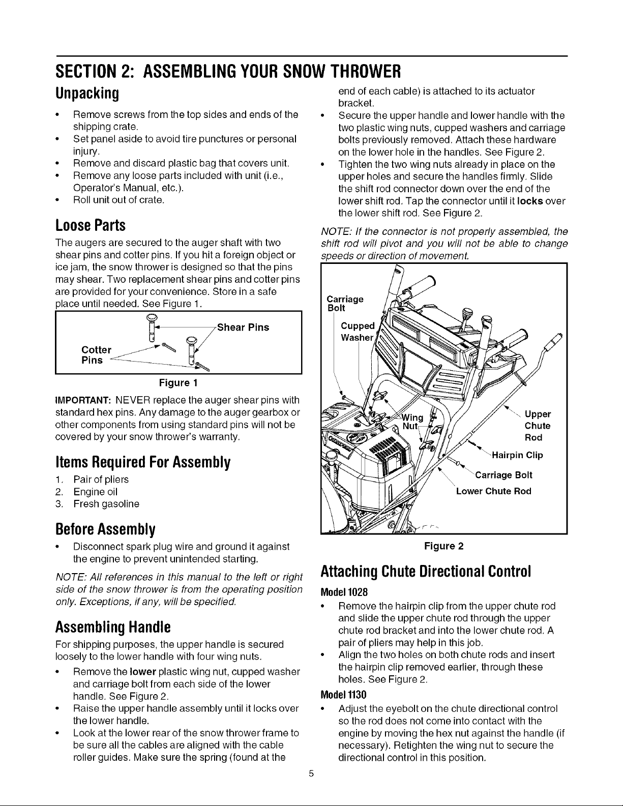
LooseParts
The augers are secured to the auger shaft with two
shear pins and cotter pins. If you hit a foreign object or
ice jam, the snow thrower is designed so that the pins
may shear. Two replacement shear pins and cotter pins
are provided for your convenience. Store in a safe
place until needed. See Figure 1.
Cotter _"_ "_
Pins .......................... U_
Figure 1
IMPORTANT: NEVER replace the auger shear pins with
standard hex pins. Any damage tothe auger gearbox or
other components from using standard pins will not be
covered by your snow thrower's warranty.
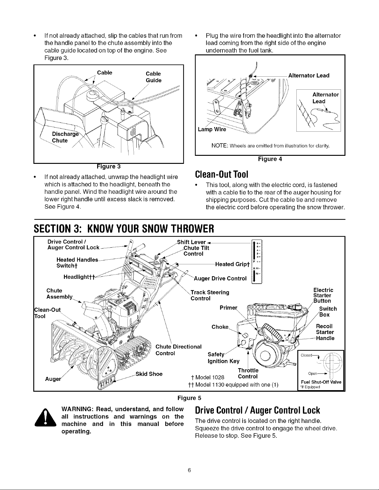
end of each cable) is attached to its actuator
bracket.
Secure the upper handle and lower handle with the
two plastic wing nuts, cupped washers and carriage
bolts previously removed. Attach these hardware
on the lower hole in the handles. See Figure 2.
Tighten the two wing nuts already in place on the
upper holes and secure the handles firmly. Slide
the shift rod connector down over the end of the
lower shift rod. Tap the connector until it locks over
the lower shift rod. See Figure 2.
NOTE: If the connector is not properly assembled, the
shift rod will pivot and you will not be able to change
speeds or direction of movement.
Carriage
ItemsRequiredForAssembly
1. Pair of pliers
2. Engine oil
3. Fresh gasoline
BeforeAssembly
• Disconnect spark plug wire and ground it against
the engine to prevent unintended starting.
NOTE: All references in this manual to the left or right
side of the snow thrower is from the operating position
only. Exceptions, if any, will be specified.
AssemblingHandle
For shipping purposes, the upper handle is secured
loosely to the lower handle with four wing nuts.
• Remove the lower plastic wing nut, cupped washer
and carriage bolt from each side of the lower
handle. See Figure 2.
• Raise the upper handle assembly until it locks over
the lower handle.
• Look at the lower rear of the snow thrower frame to
be sure all the cables are aligned with the cable
roller guides. Make sure the spring (found at the
Figure 2
AttachingChuteDirectionalControl
Model1028
• Remove the hairpin clip from the upper chute rod
and slide the upper chute rod through the upper
chute rod bracket and into the lower chute rod. A
pair of pliers may help in this job.
• Align the two holes on both chute rods and insert
the hairpin clip removed earlier, through these
holes. See Figure 2.
Model1130
• Adjust the eyebolt on the chute directional control
so the rod does not come into contact with the
engine by moving the hex nut against the handle (if
necessary). Retighten the wing nut to secure the
directional control in this position.
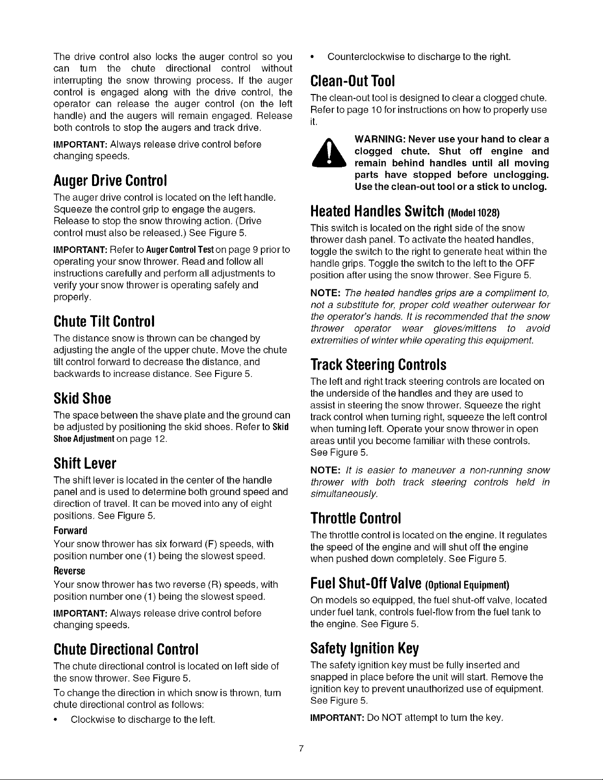
Ifnotalreadyattached,slipthecablesthatrunfrom
thehandlepaneltothechuteassemblyintothe
cableguidelocatedontopoftheengine.See
Figure3.
• Plug the wire from the headlight into the alternator
lead coming from the right side of the engine
underneath the fuel tank.
Cable Cable
Guide
J
Lar_
_ute
NOTE: Wheels are omitted from illustration for clarity.
Figure 3
If not already attached, unwrap the headlight wire
which is attached to the headlight, beneath the
handle panel. Wind the headlight wire around the
lower right handle until excess slack is removed.
See Figure 4.
Clean-0utT001
• This tool, along with the electric cord, is fastened
with a cable tie to the rear of the auger housing for
shipping purposes. Cut the cable tie and remove
the electric cord before operating the snow thrower.
SECTION3: KNOWYOURSNOWTHROWER
Drive Control / _Shift Lever.,
Aug _ _Chute Tilt
_Control
Alternator Lead
Figure 4
Switchf
Headlic
Chute
WARNING: Read, understand, and follow
all instructions and warnings on the
machine and in this manual before
operating.
_T Heated Gript
AaUcgkerst_r_ _ OntrOI
Control
Primer
Choke_@_
Chute Directional
Control
Ignition Key
t Model 1028 Control
tt Model 1130 equipped with one (1)
Figure 5
DriveControl/ AugerControlLock
The drive control is located on the right handle.
Squeeze the drive control to engage the wheel drive.
Release to stop. See Figure 5.
K
Thr )ttle
Electric
Starter
_RI_ Butt°n
Switch
ox
ecoil
Y Starter
......... Handle
Fuel Shut-Off Valve
*If Equipped
i ji
Thedrivecontrolalsolockstheaugercontrolsoyou
can turn the chute directionalcontrol without
interruptingthesnowthrowingprocess.If theauger
controlis engagedalongwith thedrivecontrol,the
operatorcan releasethe augercontrol(on theleft
handle)andtheaugerswillremainengaged.Release
bothcontrolstostoptheaugersandtrackdrive.
IMPORTANT:Alwaysreleasedrivecontrolbefore
changingspeeds.
AugerDriveControl
The auger drive control is located on the left handle.
Squeeze the control grip to engage the augers.
Release to stop the snow throwing action. (Drive
control must also be released.) See Figure 5.
IMPORTANT:Refer to AugerControlTeston page 9 prior to
operating your snow thrower. Read and follow all
instructions carefully and perform all adjustments to
verify your snow thrower is operating safely and
properly.
ChuteTiltControl
The distance snow is thrown can be changed by
adjusting the angle of the upper chute. Move the chute
tilt control forward to decrease the distance, and
backwards to increase distance. See Figure 5.
SkidShoe
The space between the shave plate and the ground can
be adjusted by positioning the skid shoes. Refer to Skid
ShoeAdjustmenton page 12.
ShiftLever
The shift lever is located in the center of the handle
panel and is used to determine both ground speed and
direction of travel. It can be moved into any of eight
positions. See Figure 5.
Forward
Your snow thrower has six forward (F) speeds, with
position number one (1) being the slowest speed.
Reverse
Your snow thrower has two reverse (R) speeds, with
position number one (1) being the slowest speed,
IMPORTANT:Always release drive control before
changing speeds,
• Counterclockwise to discharge to the right.
Clean-0utTool
The clean-out tool is designed to clear a clogged chute.
Refer to page 10for instructions on how to properly use
it.
WARNING: Never use your hand to clear a
clogged chute. Shut off engine and
remain behind handles until all moving
parts have stopped before unclogging.
Use the clean-out tool or a stick to unclog.
HeatedHandlesSwitch (Model1028)
This switch is located on the right side of the snow
thrower dash panel. To activate the heated handles,
toggle the switch to the right to generate heat within the
handle grips. Toggle the switch to the left to the OFF
position after using the snow thrower. See Figure 5.
NOTE: The heated handles grips are a compliment to,
not a substitute for, proper cold weather outerwear for
the operator's hands. It is recommended that the snow
thrower operator wear gloves/mittens to avoid
extremities of winter while operating this equipment.
TrackSteeringControls
The left and right track steering controls are located on
the underside of the handles and they are used to
assist in steering the snow thrower. Squeeze the right
track control when turning right, squeeze the left control
when turning left. Operate your snow thrower in open
areas until you become familiar with these controls.
See Figure 5.
NOTE: It is easier to maneuver a non-running snow
thrower with both track steering controls held in
simultaneously.
ThrottleControl
The throttle control is located on the engine. Itregulates
the speed of the engine and will shut off the engine
when pushed down completely, See Figure 5,
FuelShut-0ffValve(optionalEquipment)
On models so equipped, the fuel shut-off valve, located
under fuel tank, controls fuel-flow from the fuel tank to
the engine. See Figure 5.
ChuteDirectionalControl
The chute directional control is located on left side of
the snow thrower. See Figure 5.
To change the direction inwhich snow is thrown, turn
chute directional control as follows:
• Clockwise to discharge to the left.
SafetyIgnitionKey
The safety ignition key must be fully inserted and
snapped in place before the unit will start. Remove the
ignition key to prevent unauthorized use of equipment.
See Figure 5.
IMPORTANT:Do NOT attempt to turn the key.
Headlight
The headlight is on whenever the engine is running.
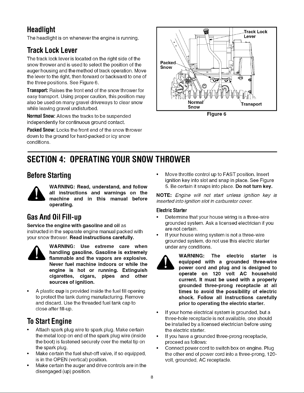
TrackLockLever
The track lock lever is located on the right side of the
snow thrower and is used to select the position of the
auger housing and the method of track operation. Move
the lever to the right, then forward or backward to one of
the three positions. See Figure 6.
Transport:Raises the front end of the snow thrower for
easy transport. Using proper caution, this position may
also be used on many gravel driveways to clear snow
while leaving gravel undisturbed.
Normal Snow: Allows the tracks to be suspended
independently for continuous ground contact.
Packed Snow: Locks the front end of the snow thrower
down to the ground for hard-packed or icy snow
conditions.
Snow
Snow
SECTION4: OPERATINGYOURSNOWTHROWER
Lever
Transport
Figure 6
BeforeStarting
all instructions and warnings on the
WARNING: Read, understand, and follow
machine and in this manual before
operating,
GasAnd0il Fill-up
Service the engine with gasoline and oil as
instructed in the separate engine manual packed with
your snow thrower. Read instructions carefully.
handling gasoline. Gasoline is extremely
WARNING: Use extreme care when
flammable and the vapors are explosive.
Never fuel machine indoors or while the
engine is hot or running. Extinguish
cigarettes, cigars, pipes and other
sources of ignition.
A plastic cup is provided inside the fuel fill opening
to protect the tank during manufacturing. Remove
and discard. Use the threaded fuel tank cap to
close after fill-up.
ToStartEngine
• Attach spark plug wire to spark plug. Make certain
the metal loop on end of the spark plug wire (inside
the boot) is fastened securely over the metal tip on
the spark plug.
• Make certain the fuel shut-off valve, if so equipped,
is in the OPEN (vertical) position.
• Make certain the auger and drive controls are in the
disengaged (up) position.
• Move throttle control up to FAST position. Insert
ignition key into slot and snap in place. See Figure
5. Be certain it snaps into place. Do not turn key.
NOTE: Engine will not start unless ignition key is
inserted into ignition slot in carburetor cover.
Electric Starter
• Determine that your house wiring is a three-wire
grounded system. Ask a licensed electrician if you
are not certain.
• If your house wiring system is not a three-wire
grounded system, do not use this electric starter
under any conditions.
equipped with a grounded three-wire
WARNING: The electric starter is
power cord and plug and is designed to
operate on 120 volt AC household
current. It must be used with a properly
grounded three-prong receptacle at all
times to avoid the possibility of electric
shock. Follow all instructions carefully
prior to operating the electric starter.
• If your home electrical system is grounded, but a
three-hole receptacle is not available, one should
be installed by a licensed electrician before using
the electric starter.
• If you have a grounded three-prong receptacle,
proceed as follows:
• Connect power cord to switch box on engine. Plug
the other end of power cord into a three-prong, 120-
volt, grounded, AC receptacle.
• RotatechokeknobtoFULLchokeposition(cold
enginestart).Ifengineiswarm,placechokeinOFF
positioninsteadofFULL.
• Pushprimerbuttontwoorthreetimesforcold
enginestart,makingsuretocoverventholein
primerbuttonwhenpushing.DONOTuseprimerto
restartawarmengineafterashortshutdown.
• Pushstarterbuttontostartengine.
• Whenenginestarts,releasestarterbutton,and
movechokegraduallytoOFF.Ifenginefalters,
movechokeimmediatelytoFULLandthen
graduallytoOFF.
• Whendisconnectingthepowercord,alwaysunplug
fromthethree-prongreceptaclefirstandthenfrom
thesnowthrower.
RecoilStarter
• Rotate choke knob to FULL choke position (cold
engine start). If engine is warm, place choke in OFF
position instead of FULL.
• Push primer button three or four times for cold
engine start. DO NOT use primer to restart a warm
engine after a short shutdown.
NOTE: Always cover vent hole in primer button when
pushing. Additional priming may be necessary for first
start if temperature is below 15°F.
Pulling the starter rope will produce a loud clattering
sound, which is not harmful to the engine or starter.
• To stop engine, move throttle control to "stop" or
"off" position.
• Remove ignition key (DO NOT turn key) to prevent
unauthorized use of equipment.
NOTE: Do not lose ignition key. Keep it in a safe place.
Engine will not start without ignition key.
• Wipe all snow and moisture from the carburetor
cover in the area of the control levers. Also, move
control levers back and forth several times.
ToEngageTrackDrive
• With the engine running near top speed, move the
shift lever into one of the six FORWARD positions
or two REVERSE positions. Select a speed
appropriate for the snow conditions that exist.
• Squeeze the auger control and the augers will turn.
Release it and the augers will stop.
• Squeeze drive control and the snow thrower will
move. Release it and drive motion will stop.
IMPORTANT:NEVER move shift lever without releasing
the drive control. Doing so will cause premature wear
on the drive system's friction wheel.
• Grasp starter handle and pull rope out slowly, until
it pulls slightly harder. Let rope rewind slowly.
• Pull starter handle rapidly. Do not allow handle to
snap back. Allow it to rewind slowly while keeping a
firm hold on the starter handle.
• Repeat the previous steps until engine starts.
• As engine warms up, rotate choke knob slowly to
OFF position. If engine falters, return to FULL
choke, then slowly move to OFF position
ToStopEngine
• Run engine for a few minutes before stopping to
help dry off any moisture on the engine.
• To help prevent possible freeze-up of starter,
proceed as follows:
ElectricStarter:
• Connect power cord to switch box on engine, then
to 120 volt AC receptacle. With the engine running,
push starter button and spin the starter for several
seconds. The unusual sound made by spinning the
starter will not harm engine or starter. Disconnect
the power cord from receptacle first, and then from
switch box.
RecoilStarter
• With engine running, pull starter rope with a rapid,
continuous full arm stroke three or four times.
ToEngageAugers
• To engage the augers and start throwing snow,
squeeze the auger control against the left handle.
• To disengage power to the augers, release both the
auger control and the drive control, if engaged.
The auger control can be locked so you can turn the
chute directional control without interrupting the snow
throwing process.
AugerControl Test
IMPORTANT:Perform the following test before
operating your snow thrower for the first time and at the
start of each winter season.
Check the adjustment of the auger control as follows:
• When the auger control is released and in the
disengaged "up" position, the cable should have
very little slack. It should NOT be tight.
• In a well-ventilated area, start the snow thrower
engine as instructed earlier inthis section under the
heading Starting Engine. Make sure the throttle is
set in the FAST position.
• While standing in the operator's position (behind
the snow thrower), engage the auger.
• Allow the auger to remain engaged for
approximately ten (10) seconds before releasing
the auger control. Repeat this several times.
• With the engine running in the FAST position and
the auger control in the disengaged "up" position,
walk to the front of the machine.
• Confirmthattheaugerhascompletelystopped
rotatingandshowsNOsignsofmotion.
IMPORTANT:IftheaugershowsANYsignsofrotating,
immediatelyreturntotheoperator'spositionandshut
offtheengine.WaitforALLmovingpartstostopbefore
re-adjustingtheaugercontrol.
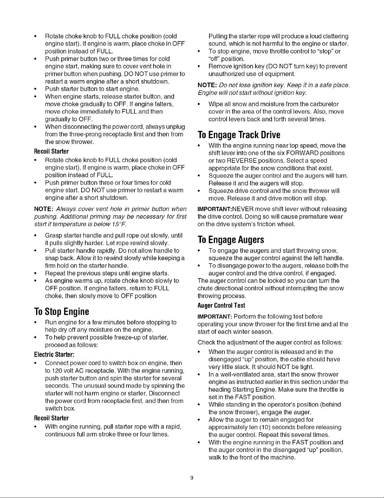
• Toreadjustthecontrolcable,loosenthehexjam
nutontheaugercontrolcable"Z"fitting.
• Rotatethecouplingendofthecable
counterclockwisetoprovidemoreslack.
• Retightenthehexjamnut.SeeFigure7.
• RepeatAugerControlTesttoverifyproper
adjustmenthasbeenachieved.
Auger
Control_
few seconds to clear any remaining snow and ice
from the chute assembly.
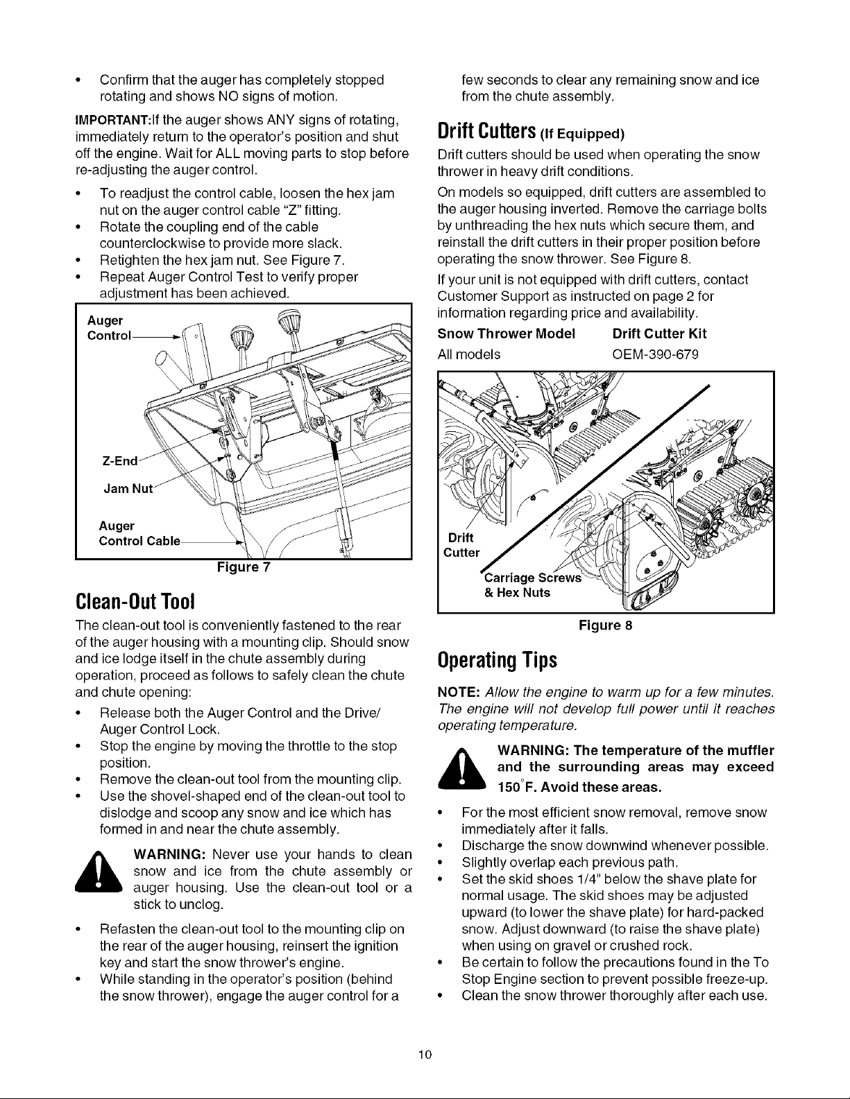
DriftCutters Equipped)
Drift cutters should be used when operating the snow
thrower in heavy drift conditions.
On models so equipped, drift cutters are assembled to
the auger housing inverted. Remove the carriage bolts
by unthreading the hex nuts which secure them, and
reinstall the drift cutters in their proper position before
operating the snow thrower. See Figure 8.
If your unit is not equipped with drift cutters, contact
Customer Support as instructed on page 2 for
information regarding price and availability.
Snow Thrower Model Drift Cutter Kit
All models OEM-390-679
Jam
Auger
Figure 7
Clean-0utT001
The clean-out tool is conveniently fastened to the rear
of the auger housing with a mounting clip. Should snow
and ice lodge itself in the chute assembly during
operation, proceed as follows to safely clean the chute
and chute opening:
• Release both the Auger Control and the Drive/
Auger Control Lock.
• Stop the engine by moving the throttle to the stop
position.
• Remove the clean-out tool from the mounting clip.
• Use the shovel-shaped end of the clean-out tool to
dislodge and scoop any snow and ice which has
formed in and near the chute assembly.
,_ WARNING: Never use your hands to clean
• Refasten the clean-out tool to the mounting clip on
• While standing in the operator's position (behind
snow and ice from the chute assembly or
auger housing. Use the clean-out tool or a
stick to unclog.
the rear of the auger housing, reinsert the ignition
key and start the snow thrower's engine.
the snow thrower), engage the auger control for a
Drift
=ge
& Hex Nuts
Figure 8
OperatingTips
NOTE: Allow the engine to warm up for a few minutes.
The engine will not develop full power until it reaches
operating temperature.
and the surrounding areas may exceed
WARNING: The temperature of the muffler
150°F. Avoid these areas.
• For the most efficient snow removal, remove snow
immediately after it falls.
• Discharge the snow downwind whenever possible.
• Slightly overlap each previous path.
• Set the skid shoes 1/4" below the shave plate for
normal usage. The skid shoes may be adjusted
upward (to lower the shave plate) for hard-packed
snow. Adjust downward (to raise the shave plate)
when using on gravel or crushed rock.
• Be certain to follow the precautions found in the To
Stop Engine section to prevent possible freeze-up.
• Clean the snow thrower thoroughly after each use.
10
 Loading...