

Page 1
4in1NarrowandStandard
G006222
Bucket
forTXSeriesCompactUtilityLoaders
ModelNo.1014in1N
ModelNo.1014in1S
FormNo.3358-434RevB
Registeratwww.T oro.com.OriginalInstructions(EN)
Page 2
Contents
Introduction
Readthisinformationcarefullytolearnhowtooperate
andmaintainyourproductproperlyandtoavoidinjury
andproductdamage.Youareresponsibleforoperating
theproductproperlyandsafely.
YoumaycontactTorodirectlyatwww.Toro.comfor
productandaccessoryinformation,helpndinga
dealer,ortoregisteryourproduct.
Wheneveryouneedservice,genuineToroparts,or
additionalinformation,contactanAuthorizedService
DealerorToroCustomerServiceandhavethemodel
andserialnumbersofyourproductready .Themodel
andserialnumbersontheproductcanbefoundon
thebucketattachment.Writethenumbersinthespace
provided.
ModelNo.
SerialNo.
Thismanualidentiespotentialhazardsandhas
safetymessagesidentiedbythesafetyalertsymbol
(Figure1),whichsignalsahazardthatmaycauseserious
injuryordeathifyoudonotfollowtherecommended
precautions.
Figure1
1.Safetyalertsymbol
Introduction.................................................................2
Safety...........................................................................3
StabilityRatings....................................................4
SafetyandInstructionalDecals.............................5
Setup............................................................................6
1InstallingtheBucketandManifold.....................6
2RemovingtheLoaderArm/AttachmentTilt
Lever................................................................6
3InstallingtheRelayHarness...............................8
4InstallingtheLoaderArm/AttachmentTilt
Lever..............................................................11
5InstallingtheValveManifoldSolenoid
Harness..........................................................12
6FinishingtheInstallation..................................13
ProductOverview......................................................15
Controls.............................................................15
Specications.....................................................15
StandardandNarrowSpecications....................15
MaximumMaterialDensityatCapacity...............15
MaximumDensityforBucketCapacity
Table..............................................................16
MaterialDensityChart—Typical.........................16
Operation...................................................................17
4in1BucketOperation......................................17
ModesofOperation...........................................17
Maintenance...............................................................19
RecommendedMaintenanceSchedule(s)................19
LubricatingtheBucket........................................19
Adjustingthe4in1BucketOperation.................19
Storage.......................................................................20
Troubleshooting.........................................................21
Schematics.................................................................22
Thismanualuses2otherwordstohighlightinformation.
Importantcallsattentiontospecialmechanical
informationandNoteemphasizesgeneralinformation
worthyofspecialattention.
©2008—TheToro®Company
8111LyndaleAvenueSouth
Bloomington,MN55420
Contactusatwww.Toro.com.
2
PrintedinAustralia.
AllRightsReserved
Page 3

Safety
Improperuseormaintenancebytheoperatoror
ownercanresultininjury.T oreducethepotential
forinjury,complywiththesesafetyinstructionsand
thoseinthetractionunit
payattentiontothesafetyalertsymbol,which
means
safetyinstruction.Failuretocomplywiththe
instructionmayresultinpersonalinjuryordeath.
Caution
Theattachmentcancrushandbreaklegs,
arms,andotherbodyparts.
•Nevergoneartheattachmentwhileitisin
operation.
•Keepallbystandersandpetsasafedistance
fromtheattachment.
•Alwaysclosethejawsoftheattachment
whennotinuse.
,
W ar ning
Operator’ s Man ual
,or
Danger
—personal
.Always
Theremaybeoverheadpowerlinesinthework
area.Shockmayoccurifyoutouchapower
linewithatreeorotherobjectthatyouare
transporting.
Surveyandmarktheareawherethereare
overheadpowerlines,anddonottransporttrees
ortallobjectsunderthepowerlines.
Theremaybeburiedpower,gas,and/or
telephonelinesintheworkarea.Shockor
explosionmayoccurifyoudigintothem.
Havethepropertyorworkareamarkedfor
buriedlinesanddonotdiginmarkedareas.
Topreventanypossibledamageanddisruptiontoany
undergroundpipeandcablenetworkinyourproposed
excavationsite,contacttheDialBeforeYouDigservice.
ThisisanAustraliannationalserviceanddialling1100
canbeusedtoaccessplansforundergroundnetwork
plansforanywhereinAustralia.Alternatively ,logonto
thewebsitewww .dialbeforeyoudig.com.auforadditional
information.
Remember,allpersonshaveaDutyofCaretoobserve
withregardtoundergroundpipesandcableswhen
diggingorexcavating.
Whentheengineisoff,attachmentsinthe
raisedpositioncangraduallylower.Someone
nearbymaybepinnedorinjuredbythe
attachmentasitlowers.
Alwayslowertheattachmentlifteachtimeyou
shutoffthetractionunit.
Whengoingupordownhill,themachinecould
overturniftheheavyendistowardthedownhill
side.Someonemaybepinnedorseriously
injuredbythemachineasitoverturns.
Operateupanddownslopeswiththeheavyend
ofthemachineuphill.Anemptybucketwill
maketherearendheavyandafullbucketwill
makethefrontendheavy.
Neglectingtodial1100beforediggingorexcavatingcan
leadtocostlydisruptiontoessentialservices,andinjury
ordeathtoworkersandbystanders.Itcanalsoleadto
heavynancialpenalties.
3
Page 4
Ifthetractionunitisttedwithanoperatorrear
platform,andyoustepofftheplatformwiththe
loadraised,themachinecouldtipforwardand
becomeunbalanced.Someonenearbymaybe
pinnedorseriouslyinjured.
Lowerthebucketbeforesteppingoffthe
platform.
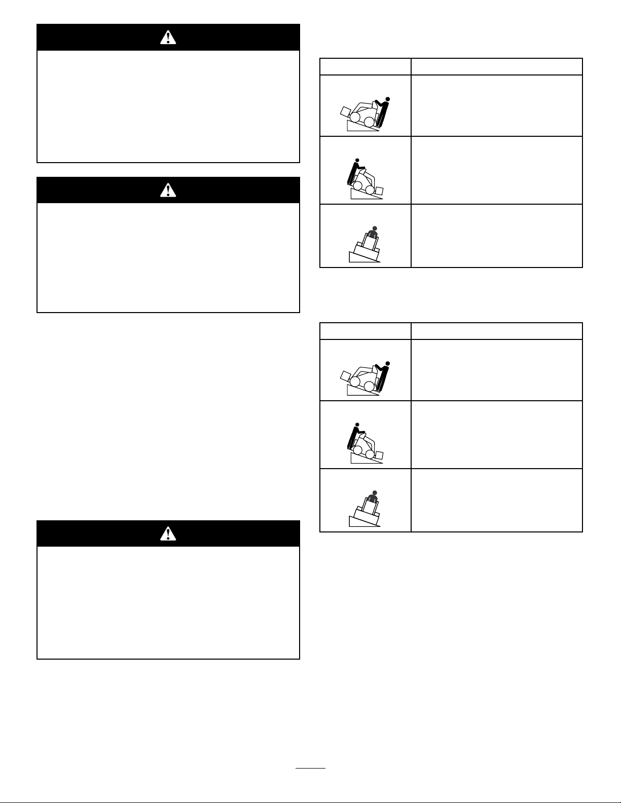
StabilityWithaLoadedBucketwithout
OperatorRearPlatform
OrientationStabilityRating
FrontUphill
B
RearUphill
D
Ifthebucketisnotkeptlevelwhilelifting,the
loadcouldbeinadvertentlydumpedonthe
operator.Theoperatorcouldbeinjuredwhen
theloadisdumped.
Whentheliftingthebucket,tiltitforwardto
keepitlevelandtopreventitfromspilling
backwards.
StabilityRatings
Todeterminethedegreeofslopeyoucantraversewith
thebucketinstalledonatractionunit,ndthestability
ratingforthehillpositionyouwanttotravelinthe
appropriatetablebelow ,thenndthedegreeofslope
forthesameratingandhillpositionintheStabilityData
sectionofthetractionunitOperator’sManual.
Thebucketmaybeusedwhenloadedorempty.
Note:Ifyourtractionunithasanoperator’ srear
platform,refertotheOperator’sManualforthatproduct
formoreinformationonstabilityratings.
SideUphill
B
StabilitywithanEmptyBucketwithout
OperatorRearPlatform
OrientationStabilityRating
FrontUphill
D
RearUphill
B
SideUphill
B
Exceedingthemaximumrecommendedslope
cancausethetractionunittotip,crushingyou
orbystanders.
Donotdrivethetractionunitonaslopesteeper
thanthemaximumrecommendedslope,as
determinedinthefollowingtablesandthe
tractionunit
Operator’ s Man ual
.
4
Page 5
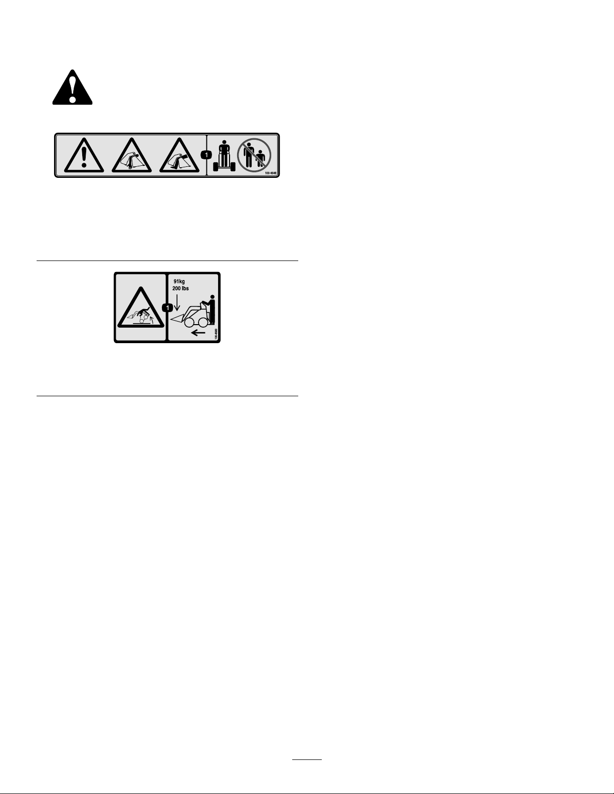
SafetyandInstructionalDecals
Safetydecalsandinstructionsareeasily
visibletotheoperatorandarelocated
nearanyareaofpotentialdanger.
Replaceanydecalthatisdamagedor
lost.
100-4648
1.Warning
2.Crushinghazardofhand,arm—keepbystandersasafe
distancefromthemachine.
3.Crushinghazardoffoot,leg—keepbystandersasafe
distancefromthemachine.
100-4689
1.Tippinghazard—maximumloadcapacityis91kg(200lb)
whentransporting.
5
Page 6
Setup
G006224
1
LooseParts
Usethechartbelowtoverifythatallpartshavebeenshipped.
ProcedureDescription
1
2
3
4
5
6
Note:Determinetheleftandrightsidesofthemachine
fromthenormaloperatingposition.
4in1bucketassembly1
Nopartsrequired
Relayharness1
Self-tappingscrews(#12[5mm])
Boxconnector1
Harnessbracket1
Loaderarm/attachmentlever
Valvemanifoldsolenoidharness
Dustcap1Finishtheinstallation.
1
Qty.
Installthebucketandmanifold.
–
2
1
1
loaderarm.RefertothetractionunitOperator’ s
Manual.
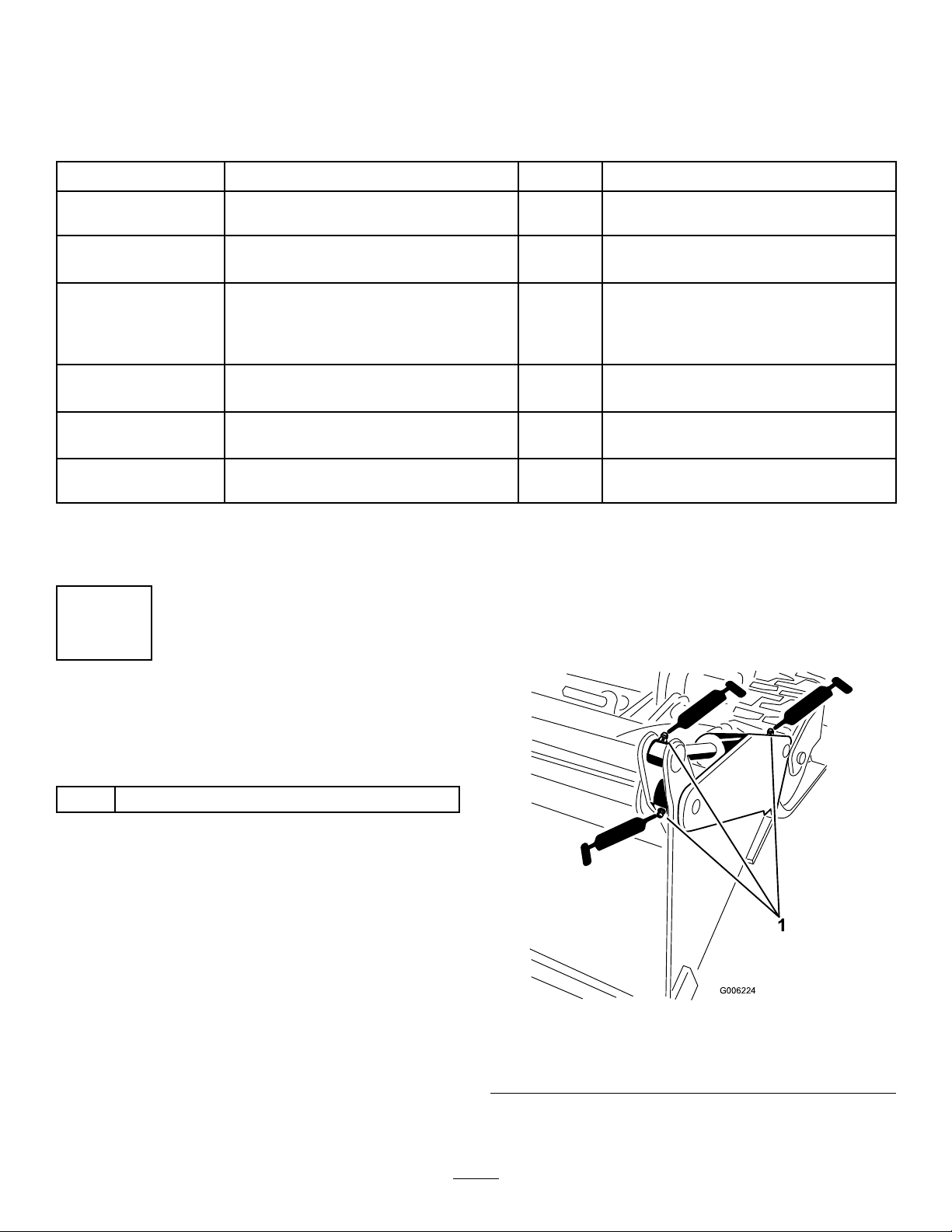
3.Usingagreasegun,pumpgeneralpurposegrease
intothesixgreasettings(threeoneachside)on
the4in1bucketuntilthegreasebeginstooozeout
(Figure3).Wipeawayanyexcessgrease.
Removetheloaderarm/attachmenttilt
lever.
Installtherelayharness.
Installtheloaderarm/attachmenttilt
lever.
Installthevalvemanifoldsolenoid
harness.
Use
InstallingtheBucketand
Manifold
Partsneededforthisprocedure:
14in1bucketassembly
Procedure
Important:Beforeinstallingtheattachment,
ensurethatthemountplatesarefreeofanydirtor
debrisandthatthepinsrotatefreely.Ifthepinsdo
notrotatefreely,greasethem.
1.Installandsecurethe4in1buckettothetraction
unit’sloaderarmmountplate.Refertothetraction
unit’sOperator’sManualformoreinformationon
connectingattachments.
2.Connectthevalvemanifoldhydraulichosestothe
matinghydraulicconnectorsonthetractionunit
Figure3
Leftsideshown
1.Greasettings
6
Page 7
2
G004182
3
2
1
G006225
2
1
G006226
3
3
2
1
RemovingtheLoader
Arm/AttachmentTiltLever
NoPartsRequired
Procedure
Theloaderarmsmaylowerwhenintheraised
positioncrushinganyoneunderthem.
Installthecylinderlockbeforeperforming
maintenancethatrequiresraisedloaderarms.
1.Raisetheloaderarmsandinstallthecylinder
safetylock.Removethehairpincotterandclevis
pinsecuringthecylinderlocktotheloaderarm
(Figure4).
6.Loosenthebatterynegative(–)cableterminalnut,
andremovethecableterminalfromthebatterypost.
Retainallparts.
7.Opentheenginehoodandsecureintheopen
positionwiththeproprod.Refertothetractionunit
Operator’sManual.
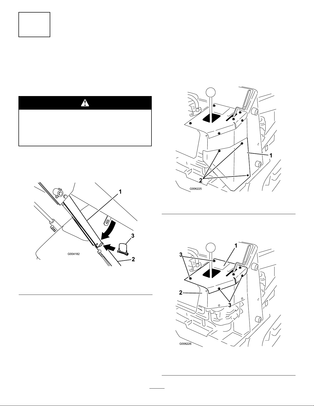
8.Removethethreescrewssecuringtherighthand
rearcoversupportassemblytothecontrolpaneland
theloadertowerassemblies(Figure5),Removethe
cover.
Figure4
1.Cylinderlock3.Clevispin
2.Liftcylinder
2.Lowerthecylinderlockoverthecylinderrodand
secureitwiththeclevispinandhairpincotter
(Figure4).
4.Hairpincotter
3.Slowlylowertheloaderarmsuntilcylinderlock
contactsthecylinderbodyandrodend.
4.Switchofftheengine,removethekeyfromthekey
switchandallowtheenginetocool.
5.Openandremovetherearaccesscover.Refertothe
tractionunitOperator’sManual.
Figure5
1.Righthand,rearcover
2.Screw
9.Removethefourscrewssecuringtherighthand
panelassemblytothecontrolpanelassembly
(Figure6).
Figure6
1.Righthandpanel
2.Controlpanelassembly
3.Screw
7
Page 8
10.Removetherighthandpanelassemblybyliftingit
G006227
2
1
G006228
1
2
3
4
5
overtheloaderarm/attachmenttiltleverandfeedit
fromtheparkingbrakelever.
4in1bucketwiringtobeinstalled:thefuelgauge,
hydraulicoiltemperature,hourmeter/tachometer
(Figure8).
Note:Onemostmodels,removingtherighthand
panelreleasestheparkingbrakeleverandtheparking
brakeswillbeapplied.
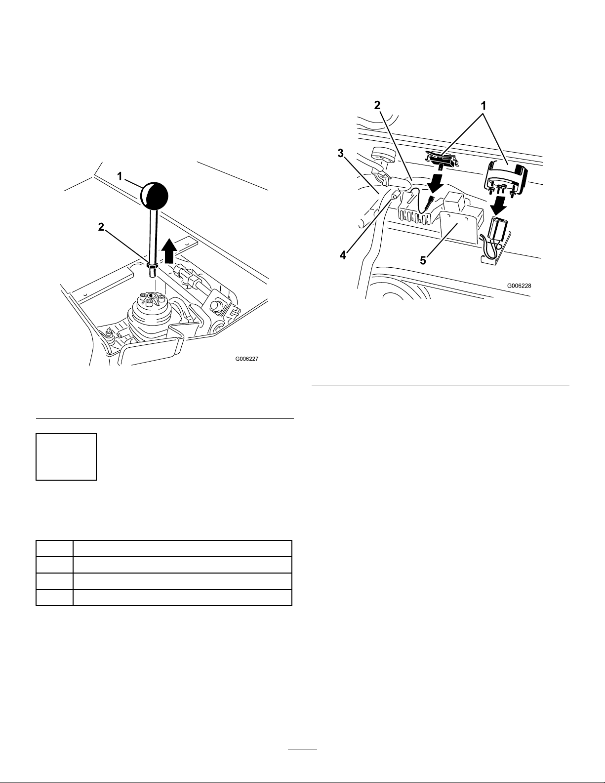
11.Loosenthelocknutatthebaseoftheloaderarm/
attachmenttiltlever(Figure8).Unscrewandremove
theleverfromthespoolvalve.
Figure7
1.Loaderarm/attachmenttilt
lever,existing
2.Locknut
Disconnectenoughcomponentstoallowthewiring
harnesstoberoutedbehindthekillandstartrelays.
Figure8
1.Dashcomponents,Interior4.Headlightpowersource,
2.Mainwiringharness,
existing
3.Openingintheframe
mainwiringharness
5.Existingkillandstart
relays
3.Locatetherightandleftrelaysattheendofthe
wiringharness(Figure9).Removetherelaysfrom
3
InstallingtheRelayHarness
Partsneededforthisprocedure:
1Relayharness
2
Self-tappingscrews(#12[5mm])
1Boxconnector
1Harnessbracket
Procedure
1.Ifaheatshieldisinstalledtoprotecttheelectrical
componentsunderthedash,removethefasteners
securingtheshieldandremovetheshieldbefore
proceeding.Retainallfasteners.
2.Disconnectthemainwiringharnessfromthe
followingdashcomponentstoallowroomforthe
8
Page 9

therelaybrackettoexposethemountingholesinthe
G006229
1
2
3
4
L
R
G006231
1
2
relaybracket.Retainallparts.
C.Drilltwopilotholes3/16inch(4.76mm)
diameteratthemarksinthemachineframe
(Figure10).Removeanydebris.
D.Replacetherelaybracketinsidethedashand
aligntheholesinthebracketwiththoseholes
previouslydrilled.
E.Securetherelayharnesstotheframewithtwo
self-tappingscrews(#12[5mm])(Figure10).
5.Installtheleftandrightrelaystotheconnector.
Replacetheconnectionsloosenedtothecomponents
onthedashtoallowtheinstallationoftherelay
harness.
6.Routetheloose,fourprongedendoftheharness
(Figure9)throughtheopeningunderthedash
showninFigure11.
Note:Takecarenottodamagetheprongsduring
routing.
Figure9
1.Relayend
2.Loaderarm/attachmentleverconnector
3.Powerconnector,toheadlightconnectorinmainharness
4.Fourprongs,shownloose
4.Securetheharnesstotheinteriorofthedash:
Figure10
1.Relayharness3.Drillhere
2.Relaybracketend
4.Selftappingscrew
Figure11
1.Relayharness2.Holeindash
7.Fromtheoperator’sposition,locatethefour
prongedendofthewireharnessandpullitpastthe
leverbase(Figure12).Makesuretheconnectorfor
thenewlevertsthroughtheopeninginthedash
andstaysclosetotheleverbase.
A.Positiontherelaybracketendoftheharness
insidethedashasshownin(Figure10)andmark
thetwoopeningsinthebracket.
B.Removetherelaybracketandharnessandverify
thetwomarksarevisible.
9
Page 10

G006232
1
2
3
Figure12
G006233
1
2
4
3
G006234
1
2
3
G006235
1
2
3
1.Relayharness3.Leverbase
2.Plug
Figure14
1.Leverarm3.Hydrauliclines,loaderarm
2.Harness,prongedend
8.Routetheharnessdown,behindthehydrauliclines
andpullitthroughtherewallintheopeningforthe
lower,righthydraulicline(Figure13).
10.Seattheharnessinthearmbyinsertingitupinto
thehollowoftheloaderarmframe.Leaveenough
harnessouttoreachthehydraulicconnectorsonthe
loaderarmfront(Figure15).
Figure13
1.Relayharness3.Firewall
2.Hydrauliclines
4.Openinginlower,right
hydraulicline
1.Loaderarm
9.Undertheleverarm,reachintotheframeandpull
loaderarm(Figure14).
theharnessup,betweenthetwohardlinesinthe
2.Hollow
11.Locatethelockingconnectorboxwiththefour
holes.Installthefourprongsintothefourholesof
theconnectorasshownanddescribedinFigure16.
Note:Seewiringdiagramformoreinformation.
Figure15
3.Lengthofharnesstoreach
hydraulicconnectors.
10
Page 11

G006236
1
1
2
2
3
3
4
4
Figure16
G006307
1
2
1
G006237
1
2
1.Yellow3.White
2.Black,Ground4.Black,Ground
12.Securetheconnectortothewireharnessbysnapping
theconnectorshutoverthewires.
13.Attheloaderarm,installtheharnessbracketas
showninFigure17.Loosenthejamnutontheright
hydrauliclineandinstallthebracketbetweenthenut
andtheloaderarmbracket.Securethebracketby
tighteningthenuttoholditagainsttheloaderarm
bracket.
4
InstallingtheLoader
Arm/AttachmentTiltLever
Partsneededforthisprocedure:
1
Loaderarm/attachmentlever
Procedure
1.Installthenewloaderarm/attachmenttiltleverto
themachine(Figure18).Screwtheshaftdownfully
intothevalve,withtheshaftleadopeningfacing
rearward(awaythecontrolpanelassembly)andthe
solenoidswitchesinahorizontalplane.
Figure17
1.Harnessbracket2.Jamnut,hydraulicline
14.Usetheclipontheconnectortosecuretheharness
tothebracketpreviouslyinstalledontotheloader
armhydrauliclines.
Figure18
1.Loaderarm/attachment
lever
2.Shaftleadopening
Note:Positioningofthesolenoidswitchescanbe
adjustedbylooseningtheupperlocknutontheshaft
andtwistingthelevertothecorrectposition.While
holdingtheleverfromrotating,tightentheupper
locknutsecurely.
2.Holdingthetiltleverfromrotating,tightentheshaft
locknutsecurelydownonthespoolvalve.
3.Looptheshaftleadclockwisearoundthespoolvalve
(Figure19).
Note:Loopingtheshaftleadaroundthespoolvalve
mustbedonetopreventtheleadfromcontacting
thetractioncontrollinkages.
11
Page 12

G006238
1
2
3
Figure19
G006239
1
2
3
1.Loaderarm/attachment
lever
2.Connector
4.Connecttheplugcomingfromnewlevertotheplug
connectorintherelaywireharness.
5.Securetherelayharnessconduittotheupper
hydraulicpipe,forwardofthespoolvalve,witha
suitablecabletie.
3.Relayharness
5
InstallingtheValveManifold
SolenoidHarness
Partsneededforthisprocedure:
1
Valvemanifoldsolenoidharness
Procedure
1.Removethesixscrewsandwasherssecuringthe
valvemanifoldcovertothe4in1bucketandremove
thecover(Figure20).Retainallparts.
Important:Securetherelayharnessbacktothe
hydraulicpipesoastoensuretheharnessand
wiringdoesnotinterferewiththeoperationof
theparkingbrakeleverand/thebrakeswitch.
6.Installtherighthandpanelassemblybyloweringit
overthenewloaderarm/attachmenttiltleverand
feedtheparkingbrakeleverthroughit.
7.Installthefourscrewsremovedpreviouslytosecure
therighthandpanelassemblytothecontrolpanel
assembly(Figure6).
8.Installtherighthandrearcoversupportandsecure
ittothemachineusingthethreescrewsremoved
previously(Figure5).
Figure20
1.4in1Bucket
2.Cover
2.Feedtheconnectorendofthevalvemanifold
solenoidharnessfromthevalvemanifoldside
throughtheinsideofthevalvemanifoldhydraulic
hoseprotectivesleeve.
3.Removetheprotectiveplugsfromthevalvemanifold
solenoidterminals.
4.Attachtheharnessconnectorstothevalvemanifold
solenoids(Figure21)withtheconnectormarked‘L’
ontheoutersolenoidandtheconnectormarked‘R’
ontheinnersolenoid(closesttothemanifold).
3.Screw,washer
12
Page 13

R
L
G006240
1
2
3
Figure21
G006242
1
1.Solenoidharness3.Connectors,leftandright
2.Valvemanifold
5.Tightenboththeconnectorcenterattachingscrews
securely.
6.Attachthevalvemanifoldsolenoidharness
connectortothematingloaderarmharness
connector(Figure22).
connectiontotheloaderarmharness.Alsoensure
thatthereissufcient‘loop’intheharnessatthe
connectorstothevalvemanifoldsolenoidsandthe
harnessisnotstrained.
9.Securethehoseprotectivesleeveandsolenoidvalve
harnesstothehydraulichosesusingsuitablecable
ties(Figure23).Tightenthecabletiessecurelyand
cutoffanyexcessstraplengths.
Figure23
1.Cableties
Figure22
1.Valvemanifoldsolenoid
harness
2.Relayharness
7.Atthevalvemanifoldhydraulichoses,positionthe
hoseprotectivesleeveequallydistantaroundthe
uppermostbendinthehose.
3.Hydraulicconnections
8.Locatethesolenoidvalveharnessinthehose
protectivesleevesothatthereissome‘slack’atthe
6
FinishingtheInstallation
Partsneededforthisprocedure:
1Dustcap
Procedure
1.Reconnectthebatterytothemachine.Connectthe
negative(black)cableterminaltothenegative(-)
batterypost.Tightentheterminalnutsecurely.
2.Installandclosetherearaccesscover.Refertothe
tractionunitOperator’sManual.
3.Closetheenginehood.Refertothetractionunit
Operator’sManual.
4.Installthekeytothekeyswitchandstarttheengine.
5.Fullyraisetheloaderarm.Disconnectandstorethe
loaderarmcylindersafetylock.
13
Page 14

6.Lowertheloaderarm,leavingthe4in1bucketclear
oftheground.
7.Totesttheoperationandinstallationofthevalve
solenoidwiring:
A.Setthethrottletofast.
B.Movetheauxiliaryhydraulicslevertotheforward
ow .
Important:
Onl y operate
thebucketjaws
withtheAuxiliaryHydraulicsLeverin
F orw ard F lo w
the
position.Attemptingto
operatethebucketjawswhileinthedetent
positioncanstoptheengine.
C.Presstherockerswitchinturnontheloader
arm/attachmenttiltlever.Thebucketshould
openandclose.
8.Releasetheauxiliaryhydraulicslevertotheneutral
position.
9.Raisetheloaderarmtothehalfwaypositionandtilt
the4in1bucketfullyforward.Checkthatthereisno
tensiononthevalvemanifoldsolenoidwireharness
attheconnectiontotheloaderarmharness.Ifthere
istension,pullthevalvemanifoldsolenoidharness
throughthecabletiesandthehoseprotectivesleeve
toreducethetension.
10.Tiltthe4in1bucketbackandlowertheloaderarm.
11.Switchofftheengine.
12.Installthevalvemanifoldcovertothe4in1
bucketandsecurewiththesixscrewsandwashers
(Figure20).Tightenthescrewssecurely.
Important:The4in1Bucketmustnotbeused
withoutthevalvemanifoldcoverinstalledand
securedinplace.Thewarrantyonthevalve
manifoldassemblywillbevoidedifthecoveris
notinstalled,orincorrectlyinstalled.
14
Page 15

ProductOverview
G006243
1
2
3
4
2
1
3
4
5
G006245
2
1
3
4
5
Toraisetheloaderarms,slowlymovetheleverrearward
(Figure25).
WiththeAuxiliaryHydraulicsLeverintheforwardow
position,usetherockerswitchonthetopofthe4in1
loaderarm/attachmenttiltlevertoopenandclosethe
jawsofthebucket.
Figure24
1.4in1bucket3.Hydraulic,electrical
2.Valvemanifoldcover4.Loaderarm/attachment
Controls
Important:
AuxiliaryHydraulicsLeverinthe
Onl y operate
thebucketjawswiththe
F orw ard F lo w
position.Attemptingtooperatethebucketjaws
whileinthedetentpositioncanstoptheengine.
Youcanalsopushtheleverfullyforwardintoadetent
position(Figure25)toreleasetheloaderarmssothatthe
attachmentrestsontheground.Thisallowsattachments
suchasthelevelerandthehydraulicbladetofollowthe
connections
lever
contoursoftheground(i.e.,oat)whengrading.
Specications
Note:Specicationsanddesignaresubjecttochange
withoutnotice.
StandardandNarrowSpecications
Standard4in1Bucket
Overallwidth1040mm(41in)
Overalllength580mm(23in)
Overallheight545mm(21in)
Weight
Capacity(SAEstruckcapacity)0.12m
127kg(280lb)
3
(4.3ft3)
Narrow4in1Bucket
Overallwidth863mm(34in)
Overalllength580mm(23in)
Overallheight545mm(21in)
1.Lowertheloaderarms
2.Raisetheloaderarms
3.Tiltthebucketrearward
Figure25
4.Tiltthebucketforward
5.Open/closethebucket
Weight
Capacity(SAEstruckcapacity)0.10m
MaximumMaterialDensityatCapacity
Thedensityofmaterialsbeingmovedbythebucket
122kg(268lb)
3
(3.5ft3)
variesandthereforesowilltheamountofagiven
materialthatcanbecarriedbythebucketbeforethe
4in1LoaderArm/AttachmentTiltLever
Totilttheattachmentforward,slowlymovetheleverto
theright(Figure25).
Totilttheattachmentrearward,slowlymovetheleverto
theleft(Figure25).
maximumloadratingisreached.Thersttablelists
thedensityofthematerialthatcanbecarried,both
heapedandstruck(i.e.,leveledoff),inthe4in1bucket.
Followingthistableisachartlistingcommonmaterials
andtheirdensities.
Tomovethematerialswithdensitiesgreaterthanthe
maximumallowedforthebucket,reducethevolumeof
Tolowertheloaderarms,slowlymovetheleverforward
(Figure25).
thematerialplacedinthebucket.
15
Page 16

MaximumDensityforBucketCapacityTable
4in1BucketCapacity
Bucket,heaped
Bucket,struck
MaterialDensityChart—Typical
Actualmaterialdensitywillvaryfromthesetypicalvalves.
MaterialDensity—LooseMaterialDensity—Loose
Caliche1250kg/m
Clay
Naturalbed
Dry
Wet
Withgravel,dry
Withgravel,wet
Coal
Anthracite,broken
Bituminous,broken
Earth
Dry,packed
Wet,packed
Loam
Granite,brokenorlargecrushed1660kg/m
(78lb/ft
1660kg/m
(104lb/ft
1480kg/m
(93lb/ft
1660kg/m
(104lb/ft
1420kg/m
(89lb/ft
1540kg/m
(96lb/ft
1100kg/m
(69lb/ft
830kg/m
(52lb/ft
1510kg/m
(94lb/ft
1600kg/m
(100lb/ft
1250kg/m
(78lb/ft
(104lb/ft
3
3
)
3
3
)
3
3
)
3
3
)
3
3
)
3
3
)
3
3
)
3
3
)
3
3
)
3
3
)
3
3
)
3
3
)
Gravel
Limestone,brokenorcrushed
Sand
Sandstone,broken1510kg/m
Shale1250kg/m
Slag,broken1750kg/m
Stone,crushed1600kg/m
Topsoil
MaximumDensity
11 10kg/m
1403kg/m
3
(70lb/ft
3
3
)
(88lb/ft
3
)
Dry
Pitrun(gravelledsand)1930kg/m
Dry13-51mm(1/2-2inch)1690kg/m
Wet13-51mm(1/2-2inch)2020kg/m
Dry
Wet
Withgravel,dry
Withgravel,wet
1510kg/m
(94lb/ft
(120lb/ft
(106lb/ft
(126lb/ft
1540kg/m
(96lb/ft
1420kg/m
(89lb/ft
1840kg/m
(115lb/ft
1720kg/m
(107lb/ft
2020kg/m
(126lb/ft
(94lb/ft
(78lb/ft
(109lb/ft
(100lb/ft
950kg/m
(59lb/ft
3
3
)
3
3
)
3
3
)
3
3
)
3
3
)
3
3
)
3
3
)
3
3
)
3
3
)
3
3
)
3
3
)
3
3
)
3
3
)
3
3
)
16
Page 17

Operation
Note:Alwaysusethetractionunittoliftandmove
theattachment.
RefertothetractionunitOperator’ sManualfor
procedurestoinstallanattachment,connecthydraulic
hosesandremoveanattachment.
Important:Alwaysdisconnecttheelectrical
connectionbeforeremovingthebucketanduse
thedustcaptocovertherelaywiringharness
connector.
4in1BucketOperation
Withthe4in1bucketattachedcorrectlytothetraction
unit’sloaderarmmountplate,andattachedtothe
hydraulicandelectricalconnectors(aspreviously
described),startandrunthemachineatfullthrottle.
RaisingandLoweringtheBucket
ModesofOperation
The4in1bucketcanbeusedinfourdifferent
operatingmodes:
•Bucket
•Blade
•Grapplebucket
•Leveler
BucketOperation
Withthejawstogether,thisattachmentcanbeusedasa
standardloaderbucket.However,byopeningthe4in1
bucketjawswithafullload,thebucketcandumpup
intoahigherarea,i.e.trucktray,spilloutastickyload,
ordribbleitscontentsbetterthanastandardbucket.
Whenloadingmaterialintothefrontofthebucket,
alwayshavethebucketlevelwiththeground,moving
forwardintothematerialtobelifted.Whenthebucket
isfull,tiltitgentlyrearwardstodecreasethelifting
resistancewhenyoulifttheload.
Tooperateahydraulicattachmentintheforward(F)
direction,rotatetheauxiliaryhydraulicsleverrearward
andpullitdowntothereferencebar(Figure26,
number1).Withtheleverinthisposition,hydraulic
powerissuppliedtothejawsofthe4in1bucket.
Figure26
1.Forwardowhydraulics
2.Reverseowhydraulics
Important:
AuxiliaryHydraulicsLeverinthe
position.Attemptingtooperatethebucketjaws
whileinthedetentpositioncanstoptheengine.
Toopenandclosethe4in1bucketjaws,pressthe
rockerswitchonthetopoftheloaderarm/attachment
tiltlever.
Onl y operate
3.Neutral
thebucketjawswiththe
F orw ard F lo w
Whentransportingaload,keepthebucketascloseto
thegroundaspossible.
BladeOperation
Withthejawscompletelyopen,youcanusetheback
ofthebucketasabladetopushmaterial.Youcanalso
partiallyclosethejawsandusingthebottomofthe
frontbuckettoknockthetopofclumpsandgradewith
therearblade.
Whenscraping,levelingandsurfacestripping,lower
thebladetotheground,ensuringthatthecuttingedge
makescontact.Thebladewillbiteintothesoilasyou
moveforward.
GrappleBucketOperation
Thejawscanalsobeusedforpickingupmaterial
byclosingthemoverobjectsormaterialstobe
transported.Thisisespeciallyusefulforpickingupthe
remnantsofapileofdirtorrocks.
Takecarewhenusingthismethodthatyoudon’tcrush
anobjectthatyouarepickingupbetweenthejaws.
Also,whengrabbinganobjectofunevendimensions
oronewhichisoffcenterinthebucket,donotapply
excessiveforceoryoumaydamagethebucket.
Note:Thespeedofopeningandclosingofthe4in1
bucketjawsisadjustable,refertoAdjustingthe4in1
BucketOperationinMaintenance,page19.
LevelerOperation
Withthejawspartiallyopenandthebuckettipped
slightlyforward,youcanusethebucketasalevelerby
17
Page 18

movingthecuttingedgesbackandforthacrossthe
surfaceoftheground.
18
Page 19

Maintenance
G006224
1
RecommendedMaintenanceSchedule(s)
MaintenanceService
Interval
Beforeeachuseordaily
Every200hours
Beforestorage
Ifyouleavethekeyintheignitionswitch,someonecouldstarttheengine.Accidentalstartingofthe
enginecouldseriouslyinjureyouorotherbystanders.
Removethekeyfromtheignitionswitchbeforeyoudoanymaintenance.
LubricatingtheBucket
ServiceInterval:Beforeeachuseordaily
Beforeeachuseordaily
Every200hours
Usingagreasegun,pumpgeneralpurposegreaseinto
thesixgreasettingsonthe4in1bucketuntilthe
greasebeginstoooze(Figure27).Wipeawayanyexcess
greasewithashopcloth.
MaintenanceProcedure
•Lubricatethegreasettings.
•Inspecttheelectricalharnessretainingties.Replaceanyifnecessary.
•Inspectthehydraulichoses.Replaceanyifnecessary.
•Paintchippedsurfaces.
Adjustingthe4in1Bucket
Operation
TheSpeedControlonthevalvemanifoldcanbeused
toadjusttheopeningandclosingspeedofthe4in1
bucketjaws.
Adjustthespeedcontrolasfollows:
1.Removethesixscrewsandwasherssecuringthe
valvemanifoldcovertothe4in1bucketandremove
thecover(Figure20).
Figure27
2.Starttheengineandraisetheloaderarmsothatthe
4in1bucketisclearoftheground.
3.Operatetheauxiliaryhydraulicsleverfromthe
neutraltoforwardowdirectionacoupleoftimes
torelieveanyhydraulicsystempressureinthevalve
manifold.
Note:Ifthereishydraulicpressureactinginthe
valvemanifoldthecontrolknobcannotbemoved.
4.Loosenthespeedcontrollockingnut(turningit
counterclockwise)toallowtheadjustmentofspeed
controlknob(Figure28).Adjustthespeedcontrol
knob:
19
Page 20

G006246
12
L
R
Figure28
1.Speedcontrolknob2.Speedcontrollockingnut
•Toincreasetheopening/closingspeedofthe
bucket,turntheknobclockwise.
•Todecreasetheopening/closingspeedofthe
bucket,turntheknobcounterclockwise.
Storage
1.Beforelongtermstorage,washtheattachmentwith
milddetergentandwatertoremovedirtandgrime.
2.Checkandtightenallbolts,nutsandscrews.Repair
orreplaceanypartthatisdamagedorworn.
3.Ensurethatallthehydraulichosecouplersare
connectedtogethertopreventcontamination
enteringthehydraulicsystem.
4.Paintallscratchedorbaremetalsurfaces.Paintis
availablefromyourAuthorizedServiceDealer.
5.Usingagreasegun,pumpgeneralpurposegrease
intothesixpivotpointgreasenipplesonthebucket
untilthegreasebeginstoexudefromthepivot
bearings.
6.Storetheattachmentinaclean,drygarageorstorage
area.Coverittoprotectitandkeepitclean.
7.Coverthebuckettoprotectitandkeepitclean.
5.Withtheenginestillrunning,operatetheauxiliary
hydraulicslevertotheforwardowposition.Refer
tothetractionunitOperator’ sManual.
6.Presstherockerswitchontheloaderarm/attachment
tiltleverandobservethespeedofthe4in1bucket
jawsopeningandclosing.
7.Operatetheauxiliaryhydraulicsleverfromthe
neutraltoforwarddirectionacoupleoftimesto
relieveanyhydraulicsystempressureinthevalve
manifold.
8.Iffurtheradjustmentisrequired,repeatinstructions
inStep4.
9.Whentheadjustmenthasbeencompleted,turnthe
speedcontrollockingnutclockwisetosecurethe
setting.
10.Lowertheloaderarmandswitchofftheengine.
11.Installthevalvemanifoldcovertothe4in1
bucketandsecurewiththesixscrewsandwashers
(Figure20).Tightenthescrewssecurely.
Important:The4in1Bucketmustnotbeused
withoutthevalvemanifoldcoverinstalledand
securedinplace.Thewarrantyonthevalve
manifoldassemblywillbevoidedifthecoveris
notinstalled,orincorrectlyinstalled.
20
Page 21

Troubleshooting
Problem
Bucketdoesnotopenorclose.
PossibleCauseCorrectiveAction
1.Electricalcircuitfault.
2.Moisturebetweenvalvesolenoidcoils
andvalvesolenoidshaft.
3.V alvemanifoldand/orinternalvalve
faulty.
4.Hydrauliccoupler(s)notcompletely
connected.
5.Anobstructioninahydraulichose.5.Findandremovetheobstruction.
6.Auxiliaryvalveonthetractionunitis
notoperating.
7.Defective4in1buckethydraulic
cylinder(s).
1.Inspectthewireharnessandelectrical
connections.RefertotheWiring
Diagram.
2.Removethenutsecuringthevalve
solenoidcoilstothesolenoidshaft.
Pullthecoilsfromshaftandcleanand
wipeawayanymoisturebetweenthe
components.Installcomponentsand
tightenthenutsecurely.
3.Repairorreplacefaultycomponent.
4.Checkthatthecouplersarecorrectly
connectedandsecured.
6.Removeandrepair/replacethevalve.
7.Replaceorrepairanydefective
hydrauliccylinder(s).
21
Page 22

Schematics
5 AMP
INLINE
FUS E
TWO TE RMINAL
CO NNECTOR
(s pare )
LEFT
S OLENOID
RE LAY AND LOADER
ARM HARNES S
VALVE MANIFOLD
SOLENO ID HARNES S
2
B
1
2
Y
DENO TES
SP LICE D
J OINT
THRE E
TER MINAL
CO NNECTO R
(looking in to co nne ctor
a t rela y an d loa der
a rm ha rnes s s ide )
4 IN 1 BUCKET WIRING DIAGRAM
RIGHT
SO LENO ID
WIRING C OLOURS
B = BLACK
BN = BROWN
GR = G REY
R = R ED
W = WHITE
Y = YELLOW
B
B
1
B
YGR
B
B
LEFT
SO LENO ID
S WITCH
RIGHT
SO LENO ID
S WITCH
LOADER ARM /
ATTACHMENT
TILT LEVER
TWO TE RMINAL
CO NNECTO R
(to h ea dlam p co nne ctor)
LEFT
SO LENO ID
RELAY
85
RIGHT
S OLENOID
RELAY
86
30
87
87 a
86
30
87
87 a
85
R
R
R
YGR
C
B
A
B
B
B
B
B
B
R
R
R
Y
GR
BR
BR
B
GY
or
Y
W
W
W
BR
GY
R
or
BR
Y
or
AA
D
C
A
B
C
D
W
B
B
FO UR
TER MINAL
CO NNECTO R
(a t loa de r arm)
A
C
BB
THRE E TER MINAL
CO NNECTOR
FO UR
TER MINAL
CO NNECTOR
(looking into co nne ctor
a t relay an d loa der
a rm ha rne ss s ide )
G006076
ElectricalSchematic(Rev.A)
22
Page 23

Notes:
23
Page 24

 Loading...