

Page 1
Light Kit
for Compact Utility Loaders
Part No. 100-8840 (4-Paw and TX Models)
Part No. 100-8940 (Chain Drive Models)
Installation Instructions
Loose Parts
Description Qty. Use
Form No. 3353-864 Rev A
Bracket
Curved (Belleville) washer
Self-tapping bolt
Light assembly, with switch
Light assembly, without switch
Flat washer
Rubber grommet
T-wire harness (kit 100–8940 only) 1
Lighting wire harness
Plastic tie
Preparing the Traction Unit
Note: If you are installing this kit on a chain-drive
traction unit, skip this section.
1. Start the engine and raise the loader arms.
2. Stop the engine and remove the key.
3. Install the cylinder locks.
4. Remove/open the front hood; refer to you traction unit
Operator’s Manual for more information.
Upgrading the Wiring of
2
2
4
1
1
4
2
1
1
Installation of the mounting bracket
Installation of the lights
Upgrade the main wire harness on chain-drive
traction units
Wiring the lights
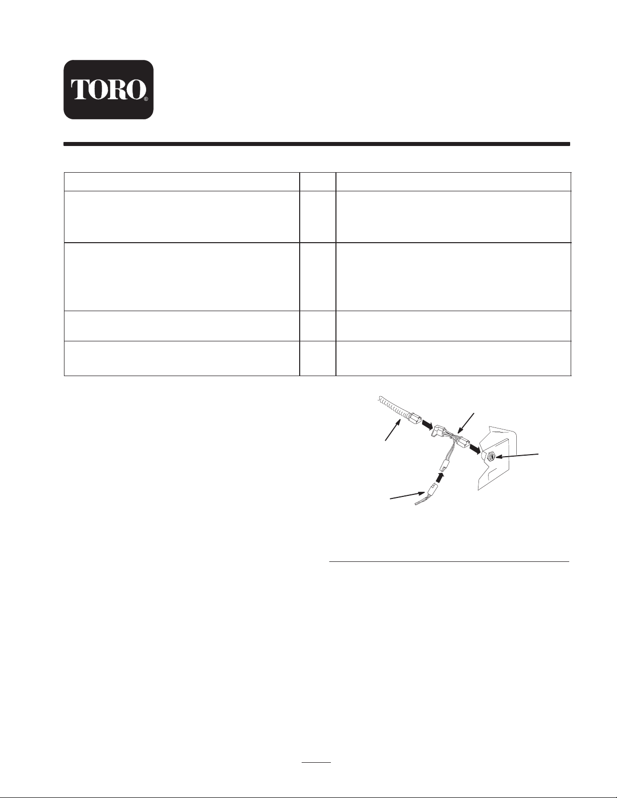
1. T-wire harness
2. Main wire harness
1
2
4
Figure 1
3. Ignition
4. Lighting wire harness
3
m–4899
Chain-Drive Traction Units
Note: If you are installing this kit on a 4-Paw or TX
traction unit, skip this section.
1. Pull the main wire harness plug off of the back of the
ignition switch.
2. Connect the T-wire harness to the main wire harness
(Fig. 1).
3. Connect the T-wire harness to the back of the ignition
switch (Fig. 1).
W 2005 by The Toro Company
8111 Lyndale Avenue South
Bloomington, MN 55420-1196
Original Instructions (EN)
Drilling Installation Holes in
Chain-Drive Traction Units
Note: If you are installing this kit on a 4-Paw or TX
traction unit, skip this section.
Some of the older chain-drive traction units do not have
holes drilled for the lights. Drill these holes as follows.
1. On the both sides of the frame, mark hole locations
2-5/8 in. (6.6 cm.) behind and 2 in. (5 cm) above the
loader arm pivot centers (Fig. 2).
Contact us at www.Toro.com
All Rights Reserved
1
Printed in the USA
Page 2
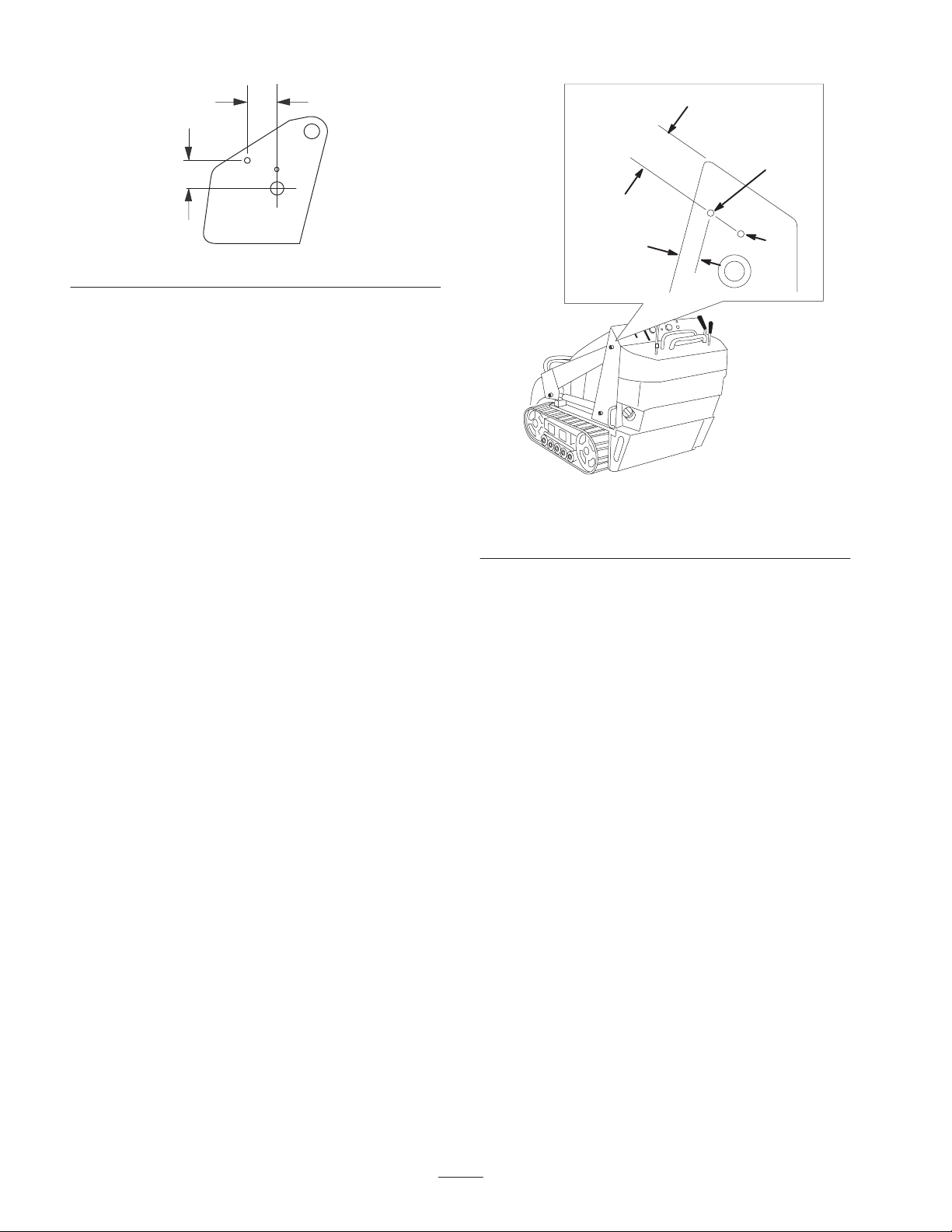
2-5/8 in. (6.6 cm)
1-13/16 in.
(4.6 cm)
2 in. (5 cm)
m–4902
Figure 2
2. At each marked location, drill a size L (0.290 in. dia.)
hole or drill and tap a 5/16–18 inch treaded hole.
Drilling Installation Holes in TX
Traction Units
Note: If you are installing this kit on a 4-Paw or
chain-drive traction unit, skip this section.
Some of the older TX traction units do not have holes
drilled for the lights. Drill these holes as follows.
1. Measure in from the edges of the frame as illustrated
in Figure 3 and mark the location of the first hole for
mounting the shield bracket.
Note: If holes exist, skip this section.
2. Use the mounting bracket as a template to locate and
mark the position of the second hole (Fig. 3).
1
9/16 in.
(1.4 cm)
Figure 3
1. First mounting hole
2. Use the bracket as a template to locate this mounting hole.
3. At each marked location, drill a size L (0.290 in. dia.)
hole or drill and tap a 5/16–18 inch treaded hole.
4. Repeat steps 1 and 3 for the other side of the traction
unit.
2
Installing the Lights on a
4-Paw or Chain Drive Traction
Unit
Note: If you are installing this kit on a TX traction unit,
skip this section.
1. Install the brackets using 2 of the self-tapping bolts
and curved washers (the cupped side of the washers
should face the traction unit) (Fig. 4).
Note: If you are installing kit number 100–8840, there
will be 2 extra bolts.
2
Page 3
1
2
7
3
4
3
9
6
5
8
m–4898
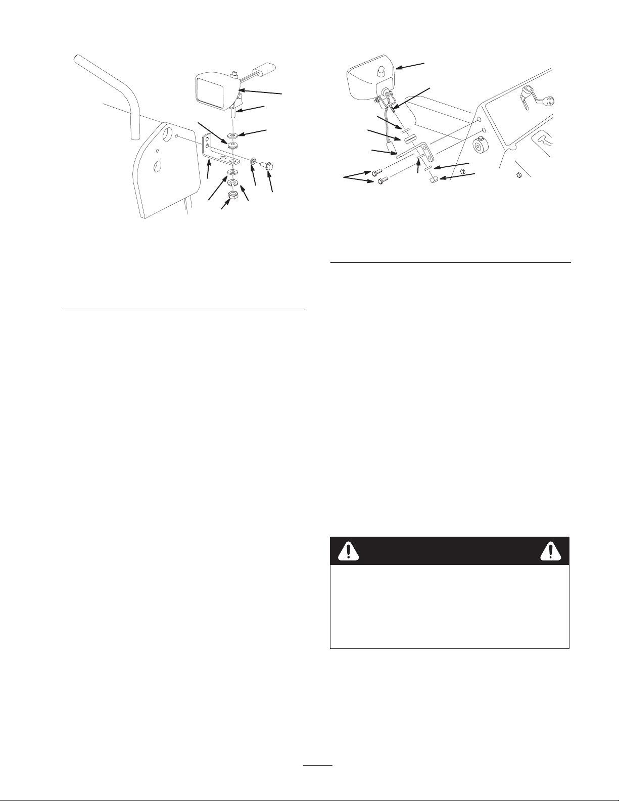
Figure 4
1. Light
2. Carriage bolt
3. Flat Washer
4. Bracket
5. Self-tapping bolt
6. Curved washer
7. Rubber grommet
8. Lockwasher
9. Nut
2. Remove and save the nut and lockwasher from the
carriage bolt on each light assembly.
3. Place a flat washer on the carriage bolt on each light
(Fig. 4).
4. Insert the rubber grommets into the outer holes in the
brackets (Fig. 4)
5. Insert the carriage bolts on each light through the
rubber grommets in the brackets (Fig. 4).
Note: Install the light with the switch on top of it on the
left side of the traction unit.
1
2
3
6
4
7
5
3
8
m–4898
Figure 5
1. Light
2. Carriage bolt
3. Flat Washer
4. Bracket
5. Self-tapping bolt
6. Rubber grommet
7. Lockwasher
8. Nut
2. Remove and save the nut and lockwasher from the
carriage bolt on each light assembly.
3. Place a flat washer on the carriage bolt on each light
(Fig. 5).
4. Insert the rubber grommets into the inner holes in the
brackets (Fig. 5)
5. Insert the carriage bolts on each light through the
rubber grommets in the brackets (Fig. 5).
Note: Install the light with the switch on top of it on the
left side of the traction unit.
6. Secure each light with a flat washer and the
lockwasher and nut you removed in step 2 (Fig. 5).
6. Secure each light with a flat washer and the
lockwasher and nut you removed in step 2 (Fig. 4).
Installing the Lights on a TX
Traction Unit
Note: If you are installing this kit on a 4-Paw or
chain-drive traction unit, skip this section.
1. Install the brackets using the 4 self-tapping bolts
(Fig. 5).
Note: You will not use the curved washers.
Wiring the Lights on a 4-Paw
or Chain-drive Traction Unit
Note: If you are installing this kit on a TX traction unit,
skip this section.
Caution
If the traction unit has been running, the hot
engine could burn you while you are routing the
wire harness.
Allow the traction unit to cool completely before
starting this procedure.
3
Page 4
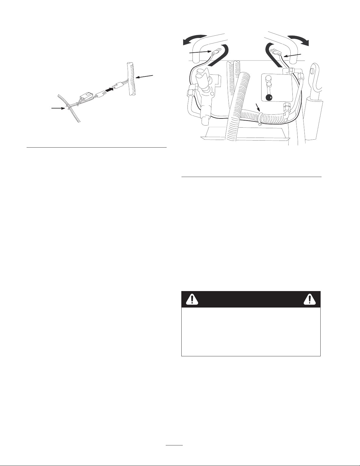
1. Connect the connector in the center of the lighting
wire harness to the connector on the main wire harness
(4-Paw traction units, Fig. 6) or T-wire harness (chain
drive traction units, Fig. 1).
2
m–4901
Figure 6
1. Main wire harness 2. Lighting wire harness
2
1
3
m–4900
1
2. Route the wires from the lights around the inside of
the operator grips.
3. Route the lighting wire harness to the sides of the
traction unit and up to the top of the control panel
(Fig. 7).
Note: Route the three pronged plug to the left side of the
traction unit and the two pronged plug to the right.
Figure 7
1. 3-prong connector
2. 2-prong connector
4. Connect the lights to the wire harness.
5. Secure the wire harness to the hydraulic line connected
to the bottom of the flow divider with a plastic tie
(Fig. 7).
6. On 4-Paw traction units, start the traction unit, remove
and store the cylinder locks, and lower the loader
arms.
3. Plastic tie
Wiring the Lights on a TX
Traction Unit
Note: If you are installing this kit on a 4-Paw or
chain-drive traction unit, skip this section.
Caution
If the traction unit has been running, the hot
engine could burn you while you are routing the
wire harness.
Allow the traction unit to cool completely before
starting this procedure.
4
Page 5

1. Remove the left and right control panel covers
(Fig. 8).
2
m-5761
Figure 8
1. Right control panel cover 2. Left control panel cover.
2. Cut a slot in each cover 3/8 in. (1 cm) deep, 3/8 in.
(1 cm) wide, and 3/4 in. (2 cm) from the edge of the
cover as illustrated in Figure 9.
3/4 in.
(2 cm)
3/8 in.
(1 cm)
1
m–5726
Figure 10
4. Install the right and left control panel covers with the
ends of the lighting harness through the notches you
cut previously (Fig. 10).
5. Connect the ends of the lighting harness to the
connectors on each light.
6. Connect the connector in the center of the lighting
wire harness to the connector on the main wire harness
(Fig. 11).
1
2
m–4901
Figure 11
1. Main wire harness 2. Lighting wire harness
3/8 in.
(1 cm)
m–5758
Figure 9
3. Route the lighting wire harness under the control panel
with the connector at the center of the harness through
the opening in the frame leading to the engine
compartment (Fig. 10).
Note: Route the three pronged plug to the left side of the
traction unit and the two pronged plug to the right.
Operating the Lights
With the traction unit running, press the switch on top of
the left light to turn on or off the lights.
5
Page 6

6
Page 7

7
Page 8

 Loading...