

Page 1
FORM NO. 3323–878
Heat Shield Kit
for 19hp Kawasaki and Kohler Engines
Part No. 100–3989
Loose
Note: Use the chart below to identify parts for assembly.
DESCRIPTION QTY. USE
Heat Shield
Flat W
Bolts
Nuts
Gaskets for Kawasaki Engine
Gaskets for Kohler Engine
Parts
ashers
IMPORTANT: This kit is for units that have
no heat sheild or have a flat heat shield
installed. If the unit has a heat shield like the
one in figure 1 then no rework is required.
1
3
3
Installing Heat Shield
3
2
2
POTENTIAL HAZARD
• Components around engine will be hot if
the machine has been running.
INSTALLATION
INSTRUCTIONS
Printed in USA
The T
oro Company – 1999
All Rights Reserved
WHAT CAN HAPPEN
• Touching hot components can cause burns.
HOW TO AV
OID THE HAZARD
• Allow the machine to cool before
performing maintenance.
• Do not touch engine components when hot.
Page 2
Installation Instructions
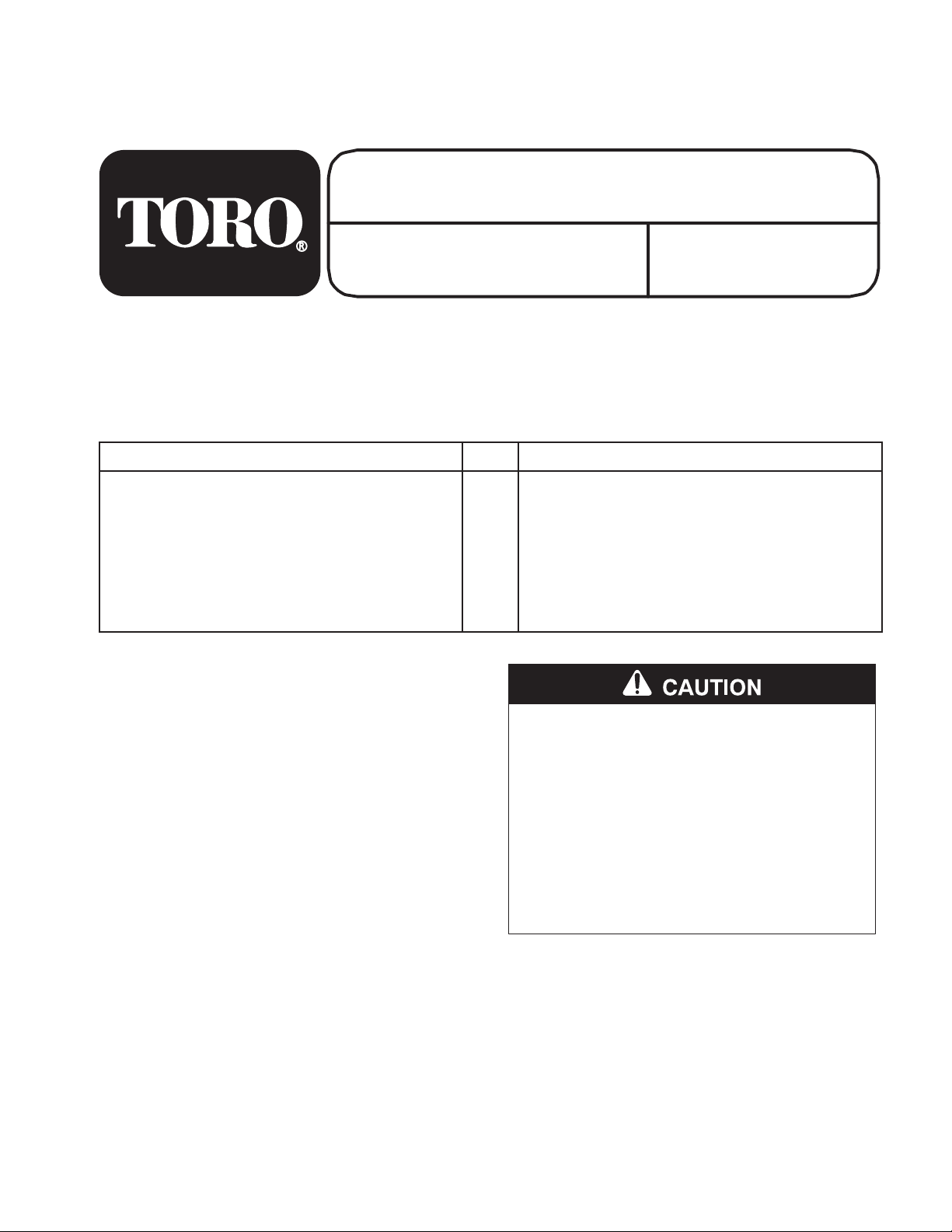
Removing
Muffler
1. Remove lock washers and nuts holding muffler
to engine manifold and the lower support
hardware. Move muffler away from engine. Save
lock washers, nuts and lower support hardware
(Fig. 1).
2. Remove all gasket material from muffler and
engine manifold.
Note: The muffler can remain in the rear
bumper area.
7
8
1. Heat
2. Muffler
3. Muf
4. Muf
Shield
fler Gaskets
fler Lower Support
Bracket and Hardware
Figure 1
61
5. Muf
6.
Lock W
7. Nut
Engine Deck
8.
9.
Rear Bumper
fler T
ubes
asher
3
m-4677
Machines
without holes in
Engine Deck and no existing
Heat Shield
Note: You have to drill holes into the engine
deck if none exist for the heat shield.
1. Check the engine deck for holes under the
exhaust manifold. If there are no holes, you will
need to drill holes into the engine deck.
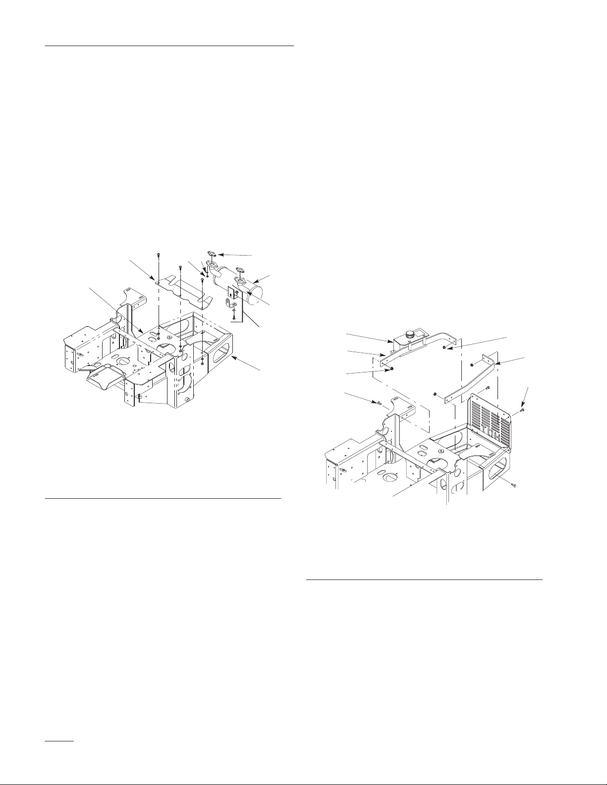
2. Remove both the left and right rear engine
guards (Fig. 2).
2
5
4
9
Note: Do not remove hydraulic reservoir
from right rear engine guard. Make
sure reservoir stays in upright position
(Fig. 2).
3
1
4
5
4
2
5
m-4730
Figure 2
1. Right
2.
3. Hydrualic
Rear Engine Guard
Left Rear Engine Guard
Up
Reservoir
Right)
(Keep
4. Nut
5. Bolt
3. Remove the four engine bolts that hold engine to
deck. This will allow you to gain access to
punch and drill holes.
2
Page 3

Installation Instructions
4. Mark and firmly center punch the two hole
locations as shown in figure 3.
Note: The middle hole does not need to be
marked.
2
1
4
1
1. 15/16”
2. 13/32”
Figure 3
Hole to Drill
3
2
3. 1”
4. T
op view of Engine Deck
Machines
with holes in Engine
Deck and no existing Heat
Shield
Note: Proceed to Installing Heat Shield on
page 4.
Machines
with a Kohler Engine
and an existing Heat Shield
1. Remove the existing flat heat shield and discard
heat shield and hardware (Fig. 4).
1
5. Drill 3/16” pilot holes and then drill 13/32”
holes into engine deck (Fig. 3).
Note: It is not necessary to install a bolt in
the middle of heat shield. The middle
hole does not need to be drilled.
6. Reinstall the four engine mounting bolts. Torque
bolts to 25–30 ft–lbs.
7. Reattach engine guard straps.
8. Proceed to Installing Heat Shield on page 4.
Figure 4
1. Existing
Flat Heat Shield
(Remove)
2. Proceed to Installing Heat Shield on page 4.
3
Page 4

Installation Instructions
Machines
with a Kawasaki
Engine and an existing Heat
Shield
1. Loosen all engine mounting bolts.
2. Remove the rear engine bolts and tip engine
forward to gain access to center heat shield bolt.
3. Remove the existing flat heat shield and discard
heat shield and hardware (Fig. 4).
4. Loosely install new hardware in the center slot in
the engine deck (Fig. 5).
5. Reinstall the engine bolts and tighten all engine
bolts to 25–30 ft–lbs.
6. Proceed to Installing Heat Shield on page 4.
2
Installing
Heat Shield
1. Position heat shield on top of the engine deck
with large slots toward the rear of the machine.
Align slots in heat shield with holes or slots in
engine deck (Fig. 6).
Note: If center bolt is installed, make sure the
center slot engages the neck of the
carriage bolt.
2. Install bolts, flat washers, and locknuts. Do not
tighten hardware. (Fig. 6).
Note: If you drilled holes in the engine deck,
the middle bolt, flat washer and lock
nut will not be installed.
3. Install appropriate gaskets onto the engine
manifold (Fig. 1). Determine the correct gaskets
by which fits correctly on mainifold.
4. Install muffler onto the engine manifold with
lock washers and nuts. Install muffler lower
support bracket and hardware (Fig. 1 and 6).
1. Heat
Shield
Figure 5
2. Center
Installed)
1
Hardware (Loosely
5. Position heat shield as far rearward as possible
and tighten bolts, flat washers and locknuts (Fig.
6).
2
4
5
6
1. Heat
2.
Engine Deck
3. Muf
4. Bolt
Shield
fler T
ubes
Figure 6
Flat W
5.
6. Locknut
7.
asher
Large Slot in Heat Shield
2
1
7
4
 Loading...