

Page 1

Form No. 3322-861
Kawasaki
Zone Start Engine Coversion Kit
For Toro Walk Power Lawn Mowers
Model 100-2863
Loose
Note:
DESCRIPTION QTY. USE
Discharge Tunnel
Latch Plate
Discharge Door Assembly
Door Retainer
Self-tapping Screw – 1/4-10 x .60
Screw – 3/8-16 x 1.5
Engine Decal
Parts
Use the following chart to identify the parts you will use to install the kit.
1
1
1
1
2
3
1
Installing the new discharge tunnel and the
door assembly
Replacing the engine
Installation
Instructions
Clamp 1
Bolt 1
Throttle Control
Throttle Cable
E-Ring
Engine Guard
Screw – 1/4-20 x 1.00
Cable T
T
only)
Screw – 3/8-16 x 1.00
Locknut – 3/8-16
ie 4
raction Control Decal (Self-propelled models
Installing the brake cable on the engine
1
1
2
1
4
1
2
2
Replacing the throttle cable
Installing the engine guard on the front of the
lawn mower
Attaching the guard to the lawn mower
Securing the cables to the deck (1)
Securing the brake cable to the right side of the
handle (2)
Installing the cables to the lower left side of the
handle (1)
Replacing the decal
Filling the holes left from removing the fuel tank
bracket
E1999 The T
8111 Lyndale Ave. South
Bloomington, MN 55420–1196
oro Company
All Rights Reserved
Printed in the USA
Page 2
Installation Instructions
DESCRIPTION USEQTY.
Square Key 3/16 x 1.25 (HP Models) or
3/16 x 0.50 (SP Models)
Oil Drain T
Brake Cable
Blade Retainer
Blade Spacer
Drive Pulley (SP Models only)
Before
POTENTIAL
•
If you leave the wir
someone could accidentally start the engine.
WHA
•
Someone accidentally starting the engine can
seriously injur
HOW T
•
Disconnect the wir
you install the kit. Set the wir
does not accidentally contact the spark plug.
ube 1
Installing
HAZARD
e on the spark plug,
T CAN HAPPEN
e you or other bystanders.
O AVOID THE HAZARD
e fr
om the spark plug befor
e aside so that it
1
1
1
1
1
Installing the blade assembly
Draining the engine oil
Replacing the brake cable
Replacing the blade retainer and the drive
pulley
3.
Connect the wire to the spark plug.
4.
Start the engine and let it run until it runs out of fuel.
5.
Disconnect the wire from the spark plug.
6.
Drain the engine oil (Refer to your operator’s manual
for the procedure).
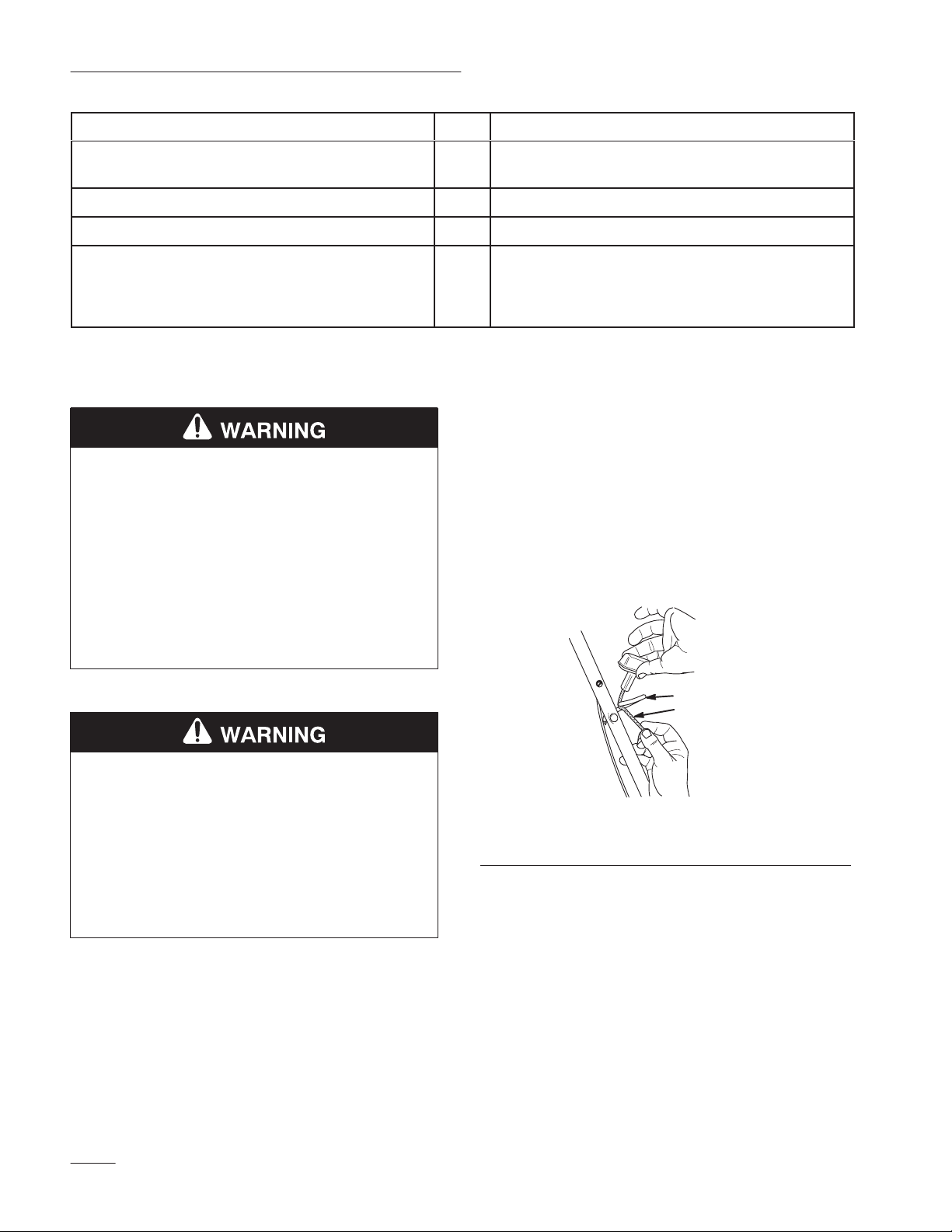
Disassembly
Removing the Starter Rope
Remove
e
the starter rope from the rope guide (Fig. 1).
1.
Disconnect the wire from the spark plug.
POTENTIAL HAZARD
•
If gasoline is spilled on a hot engine, it could
ignite.
WHA
T CAN HAPPEN
•
Contact with burning gasoline could cause
serious personal injury
HOW T
•
2.
Note:
for draining the fuel.
O AVOID THE HAZARD
Drain the gasoline fr
Make sure that the engine is cool. Remove the cap
from the fuel tank and use a pump-type syphon to
drain the fuel into a clean, approved gasoline
container.
This is the only procedure that T
.
om a cold engine only
oro recommends
1
2
m–2705
Figure
1. Rope
.
Removing the Cable Ties
Cut
guide
the cable ties that hold the cables to the handle.
1
2.
Starter rope
Removing the Fuel Tank
1. Disconnect
the fuel line from the engine (Fig. 2).
2
Page 3
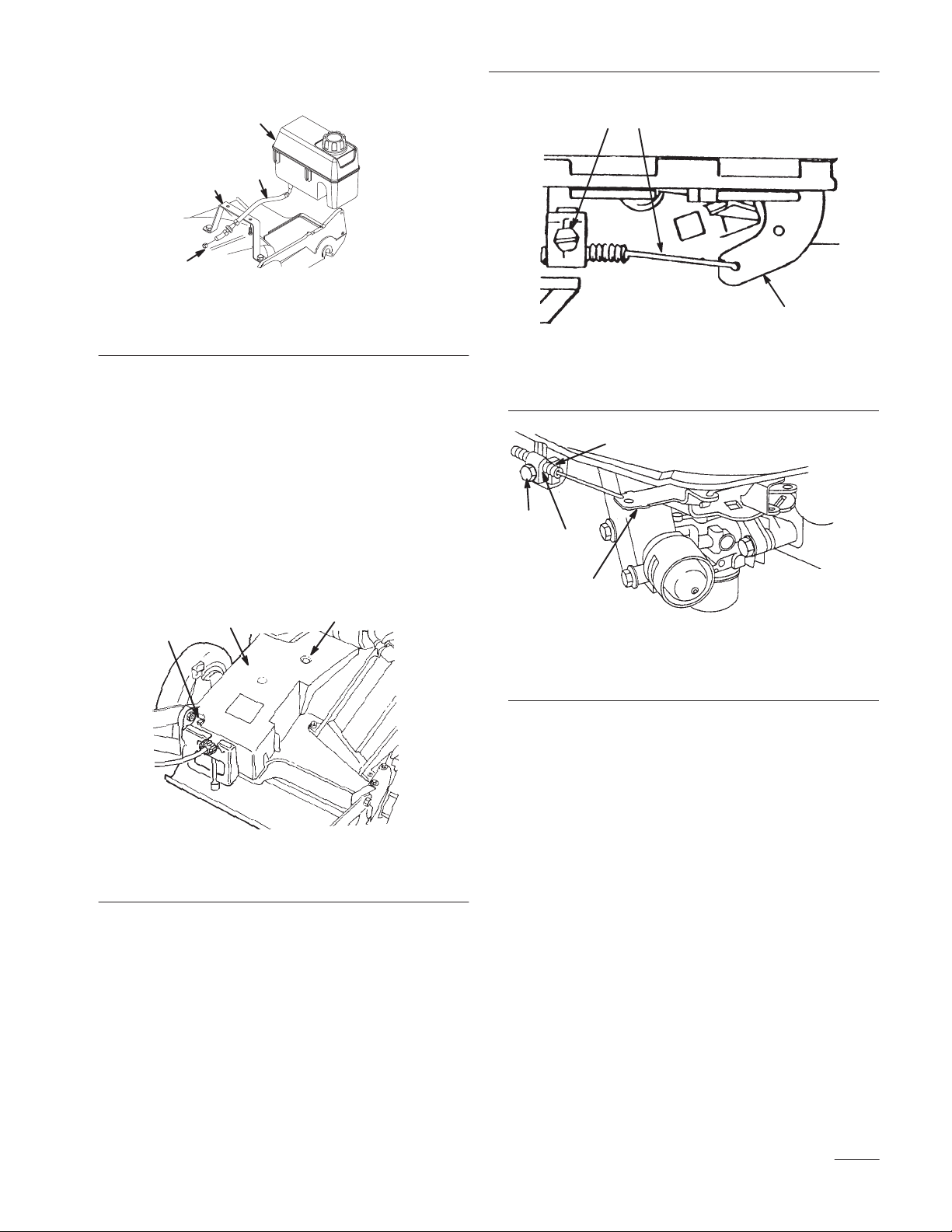
Installation Instructions
4
2
3
1
1. Fuel
line clamp
2.
Fuel line
2. Remove
Figure
the fuel tank from the tank bracket
2
3. T
4.
ank bracket
Fuel tank
(Fig. 2).
3.
Remove the tank bracket.
4.
Install two screws and two locknuts to fill the holes
left from removing the tank bracket.
Disconnecting the Throttle Cable
1. Remove
cover to the lawn mower deck (Fig. 3). Set the cover
and the fasteners aside for the installation.
two self-tapping screws that secure the belt
1. Cable
2.
Throttle cable
1
1
clamp screw
3
2
4
2
Figure
4
3.
Throttle lever
3
m-286
1
2
2
m-224
1. Belt
cover
2. Loosen
Figure
the cable clamp screw and disconnect the
3
2.
Self-tapping screw (2)
throttle cable from the throttle lever (Fig. 4 or Fig. 5).
1. Cable
2.
Cable clamp
Figure
clamp screw
5
3.
Throttle cable
4.
Throttle arm
Disconnecting the Blade Brake Cable
1. Disconnect
(Fig. 6).
the blade brake cable from the brake arm
3
Page 4

Installation Instructions
4
13
11
10
2
Figure
1. Brake
2.
2. Use
cable
Brake arm
a pliers to squeeze the tabs on the top and the
6
3.
Brake cable fitting
4.
Brake assembly
bottom of the blade brake cable fitting, and slide the
cable out of the brake assembly (Fig. 6).
Self-pr
opelled Models only
3.
Cut the cable ties that secure the blade brake cable to
the right side of the handle.
4.
Remove the cable support, the screw
, and the nut from
the right side of the handle.
5.
Remove the blade brake cable from the cable support.
6.
Unhook the blade brake cable from the control bar
control lever
7.
Retain the cable support, the screw
.
, and the nut for
installing the new cable.
Removing the Blade Assembly
1. Remove
stiffener/accelerator
spacer
protector (Fig. 7).
the blade bolt, the lock washer, the blade
, the blade, the blade retainer
, and the square key
, and the crankshaft
, the
7
6
4
5
3
2
1
Figure
1. Blade
2.
3.
4. Blade
5.
6. Spacer
7.
Note:
square key
2.
bolt
Lock washer
Blade stif
Blade retainer
Square key
fener/accelerator
Discard the old blade retainer
.
Remove the crankshaft protector by removing three
7
8.
Self-tapping screw (3)
9.
Internal lock washer (3)
10.
Crankshaft protector
11.
Engine drive pulley
(self-propelled models
only)
, the spacer
self-tapping screws and three internal lock washers.
Note:
Keep all these items for the installation.
3.
Remove and discard the engine drive pulley
(self-propelled models only).
Removing the Old Engine
Remove
engine of
engine.
the three engine screws and carefully lift the
f the housing (Fig. 8). Discard the screws and the
9
8
, and the
4
Page 5

Installation Instructions
1
2
Figure
1. Engine 2. Engine
Note:
Figure 8 shows the GTS 150 engine. The GTS 200
8
screw (3)
engine is not shown.
Removing the Discharge Tunnel
Assembly
1. Remove
locknuts, a 1/2 in. hex head washer screw
hex head washer screw that secure the dischar
assembly to the lawn mower housing (Fig. 9).
two capscrews, two flat washers, two
11
6
12
, and a 3/4 in.
ge tunnel
2. Lift of
3.
f the dischar
ge tunnel assembly (Fig. 9).
Remove the spring bracket and the spring extension
(Fig. 9).
Note:
Keep these items for the installation.
4.
Discard the dischar
Conversion
ge tunnel assembly (Fig. 9).
Kit Installation
Installing the New Discharge Tunnel
1. Position
deck. Align the holes in the dischar
holes in the lawn mower deck.
2.
Fasten the rear
dischar
capscrews, two flat washers, and two locknuts
previously removed.
3.
Fasten the front-right side of the dischar
the lawn mower deck using the 1/2 in. hex head
washer screw previously removed.
4.
Fasten the front-left corner of the dischar
the spring bracket to the lawn mower deck using the
3/4 in. hex head washer screw previously removed.
5.
Install the new dischar
with the new door retainer
the new dischar
ge tunnel on the lawn mower
ge tunnel with the
-left and the rear-right corners of the
ge tunnel to the lawn mower deck using two
ge tunnel to
ge tunnel and
ge door assembly and secure it
.
8
1
5
1. Discharge
2.
Capscrew (2)
3.
Flat washer (2)
4.
Locknut (2)
5.
Hex head washer screw
(1/2” long)
6.
Hex head washer screw
(3/4” long)
Note:
tunnel
Keep all these items for the installation.
7
Figure
9
9
10
2
3
4
7.
Spring bracket
8.
Spring extension
9.
Latch plate
10.
Self-tapping screw (2)
11.
Door retainer
12.
Discharge door assembly
6.
Install the new latch plate to the dischar
ge tunnel using
two new self-tapping screws.
7.
Hook one end of the spring extension through the hole
on the spring bracket and the other end onto the
dischar
ge door handle.
8.
Open and close the dischar
dischar
ge tunnel door closes when you release the
ge door to ensure that the
handle.
Installing the New Engine
1. Carefully
housing.
Install and tighten the three new engine screws
2.
(Fig. 10). T
(28 to
45 N
For Self–pr
3.
Install a new engine drive pulley
4.
Install the belt onto the pulley
set the new engine onto the lawn mower
orque the engine screws to 250 to 400 in-lb
Sm).
opelled Models
.
.
5
Page 6

Installation Instructions
2
1
3
m-46792
Figure
1. Engine 2. Engine
10
screw (3)
Installing the Blade Assembly
Install
the blade assembly in the reverse order of
disassembly
page 4.
Note:
(Fig. 7).
Note:
tighten the mounting screws (Fig. 7). Insert a shim (a
business card works well) between the crankshaft
protector and the hub on the blade retainer
mounting screws and remove the shim.
. Refer to
Removing the Blade Assembly
Install a new blade retainer with a spacer and a key
When you install the crankshaft protector
. T
ighten the
, do not
on
1
m-4678
Figure 11
1. Front
2.
2. Install
quadrants
Hex head screw (4)
3.
Engine guard
the new engine guard on the front of the lawn
mower deck with four hex head screws as shown in
Figure 1
1.
Installing the New Throttle Control
1. Hand
Note:
Note:
Push Models Only
– Disconnect the brake and
throttle cables from the throttle control by removing
the E-rings (Fig. 12).
Discard the E-rings.
Self-pr
opelled Models Only - Disconnect the traction
and throttle cables from the throttle control by
removing the E-rings (Fig. 12).
Discard the E-rings.
Note: T
orque the blade bolt to 50 ft-lb (68 N
Installing the Engine Guard
1. Remove
(Fig. 1
four hex head screws from the front quadrants
1). Leave the quadrants in place.
m).
4
1. Throttle
2.
3.
4. E-ring
control
Brake cable (HP model)
T
raction cable (SP model)
Throttle cable
1
8
3
7
2
Figure
12
Hex head screw (2)
5.
6.
Curved washer (2)
7. Seal
8.
Bag support rod
6
5
6
6
Page 7

Installation Instructions
2. Remove
the two hex head screws and two curved
washers that secure the throttle control to the handle
(Fig. 12).
Note:
Keep the screws and washers. Discard the throttle
control and the throttle cable.
3.
Install the new throttle control using two hex head
screws and two curved washers previously removed.
4.
Connect the new throttle cable to the throttle control
using a new E-ring.
5.
Connect the brake cable or the traction cable,
depending on the lawn mower
6.
Route the cables behind the bag support rod.
7.
Connect the brake cable to the throttle control
.
(hand-push models only) or to the brake cable
(self–propelled models only) using a new E-ring.
8.
Connect the brake cable to the engine, leaving
approximately 1/4 in. of cable to extend beyond the
cable clamp (Fig. 14).
9.
Install the belt cover using the fasteners previously
removed (Fig. 3).
10.
Make sure that the seals on the cables are pushed down
tight (Fig. 12).
11.
Route the throttle cable across the top of the
transmission as shown in Figure 13.
2
1
5
4
6
1. Cable
2.
3.
2. Move
3.
clamp screw
Cable clamp
Throttle cable
the throttle to the
Align the hole of the speed control lever with the hole
1
Figure
14
4.
5.
6.
(F
AST) position.
3
2
Speed control lever
Blade brake cable
Base plate hole
in the base plate by inserting a 7/32-in. (6 mm)
diameter pin through both holes.
4.
Pull the throttle cable to remove the slack.
5. T
ighten the cable clamp screw
Restrain the throttle and brake cables to the lawn
6.
.
mower housing with a cable tie to prevent the cables
from contacting the gear box belt guide.
Do not secur
the cables tight against the housing.
e
1
2
1. Throttle
2.
Blade brake cable
Figure
cable
13
3.
Cable tie
Adjusting the Throttle Control
1. Connect
the engine (Fig. 14).
the throttle cable to the speed control lever on
7.
Install the new blade brake cable, cable clamp, and the
cable clamp screw to the engine (Fig. 14).
3
Adjusting the Blade Brake Cable
1. Check
the brake cable adjustment by moving the
control bar toward the handle until there is no slack in
the wire (Figs. 15 and 16).
Note:
Ensure that the gap between the brake lever and the
handle is 3/16 in. to 1/4 in.
2. T
o adjust the cable, do the following procedure:
7
Page 8

Installation Instructions
Hand Push Models Only:
A.
Loosen the jam nut on the brake cable (Fig. 15).
1
2
3
4
5
6
Hand
Push Model
1. Handle
2.
Brake lever
3. 3/16”-1/4”
B. Insert
Figure
a 3/16 in. to 1/4 in. object between the brake
15
Cable adjuster
4.
5.
Jam nut
6.
Cable conduit
lever and the handle (Fig. 15).
483
E. Pull
down on the cable conduit until there is no
slack in the wire.
F. T
ighten the nut.
G.
Secure the blade brake cable to the right side of the
handle with two cable ties.
Installing the Starter Rope in Rope Guide
Install
the starter rope in the rope guide (Fig. 1).
Installing the New Cable Ties
Attach
the cables to the lower left side of the handle using
the new cable ties.
Self-pr
opelled Models Only:
the control bar with the new decal (Fig. 17).
Replace the old decal on
1
C. T
urn the cable adjuster on the brake cable until
there is no slack.
D. T
ighten the nut.
Self-pr
opelled Models Only:
A.
Insert the blade brake cable into the cable support.
B.
Assemble the cable support to the right side of the
handle.
C.
Hook the blade brake cable to the control bar lever
D.
Insert a 3/16 in. to 1/4 in. object between the brake
Do not tighten the locknut.
lever and the handle (Fig. 16).
1
2
3
4
16
3.
3/16 in. to 1/4 in.
4.
Cable bracket
Self-propelled
1. Handle
Brake lever
2.
Figure
Model
Figure
1. Decal
17
Installing the New Engine Decal
Install
the new decal on the engine as illustrated in
Fig. 18.
.
1
Figure
1. Decal
Before
For
location
Starting the Engine
information on how to fill the crankcase with oil,
fill the fuel tank with gasoline, and operate the engine,
r
efer to your
Kawasaki Engine Owner’s Manual
18
.
8
 Loading...