

Page 1
Pivot Bracket Kit
for OFZ
FORM NO. 3323-104
Part No. 100–2449
Loose
Note: Use the chart below to identify parts for assembly.
DESCRIPTION QTY. USE
Pivot Bracket
Removing
1. Disengage the power take off (PTO), set the
2. Remove hairpin cotters and clevis pins from
Parts
the Mower
parking brake, and turn the ignition key to
“OFF” to stop the engine. Remove the key.
mower hanger brackets and separate mower from
carrier frame (Fig. 1).
1
Install Pivot Brackets
4. Place a block, approximately 4 inches high,
under the carrier frame. This will raise the frame
vertically.
5. Check to see if tension has been removed from
the spring assemblies. If tension remains add
blocks to raise carrier frame higher.
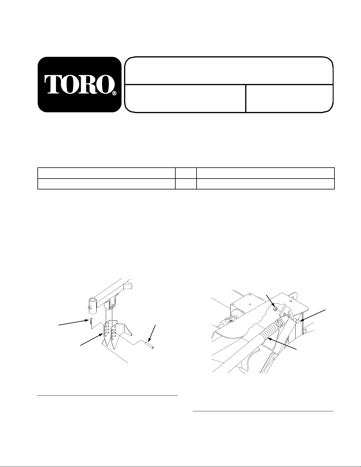
6. Remove 3/8” x 7/8” (23 mm) shoulder bolts and
3/8” locknuts securing spring end plate
assemblies to carrier frame (Fig. 2).
INSTALLATION
INSTRUCTIONS
3
1. Mower
2.
Clevis Pin
1
Hanger Bracket
Figure 1
3.
Hairpin Cotter
2
3. Fold carrier frame into its upright position.
The T
Printed in USA
1. Spring
2.
Shoulder Bolt 3/8” x 7/8”
(22 mm)
oro Company – 1999
All Rights Reserved
Assembly
3
Figure 2
3.
Locknut 3/8”
2
1
Page 2
Installation Instructions
7. Remove the block under the carrier frame.
8. Unfold carrier frame.
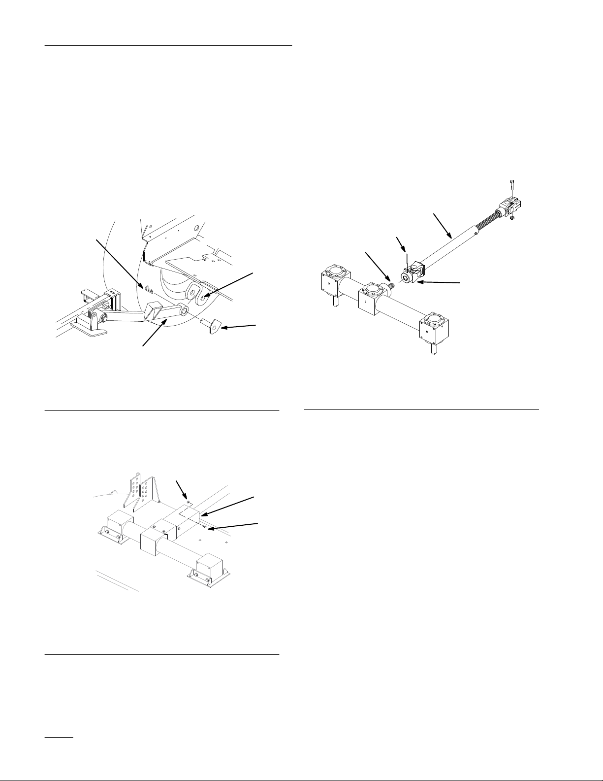
9. Remove hairpin cotters and pivot pin assemblies
securing push arms to traction unit pivot
brackets (Fig. 3).
Note: Save all hardware for use when
installing mower. Items 3 and 4 are
part of traction unit.
4
1
3
m-3937
1. Pivot
2.
Push Arm
Bracket
2
Figure 3
3.
Pivot Pin Assembly–flat
4.
Hairpin Cotter
11. Drive roll pin through hole in universal joint to
remove PTO drive shaft from gearbox shaft
(Fig. 5).
Note: Drive shaft remains with traction unit.
12. Move deck and carrier frame away from traction
unit.
1
4
3
2
m-3376
Figure 5
1. PTO
2.
Driveshaft
Universal Joint
3.
Gearbox shaft
4.
Roll Pin
10. Remove 5/16–18 x 7/8” (11 mm) shoulder bolt
and 5/16” flange nut holding PTO cover down
(Fig. 4).
3
1
2
m-3718
Figure 4
1. PTO
2.
cover
Shoulder bolt
5/16–18 x 7/8” (1
1 mm)
3.
Flange nut 5/16”
Remove
Existing Pivot
Brackets
1. Jack up machine until the drive wheels are off
the floor. Use jack stands or block the machine
to prevent it from falling accidentally.
2. Remove the drive wheels.
IMPORTANT: Remove all grasss and debris
from wheel motor mounts and area around
them.
3. Remove the existing pivot brackets on the
machine. Remove any welding that exists.
4. Remove paint from areas that will be welded,
including new pivot brackets.
2
Page 3

Installation Instructions
Installing
New Pivot Brackets
The pivot brackets need to be installed with a jig, part
number 100–2444. The jig is available through the
Toro Parts Department.
Note: Apply anti–splatter to jig pins to
prevent weld splatter from sticking to
jig pins (Fig 7). Obtain this locally.
1. Install one of the new pivot brackets onto jig
(Fig 6).
1
3
4
5
2
Figure 6
1. Jig
2. Pivot
3. V
Bracket
ertical Plate (Flush to
side of motor mount)
4.
Base Plate (Flush to
bottom of motor mount)
5.
Bracket surface (Flush to
front of motor mount)
7. Reinstall mower deck.
2
3
5
4
Figure 7
1. OFZ
2.
3.
Frame
Wheel Motor Mount
Right–hand Pivot Bracket
4.
Jig and Left–hand Pivot
Bracket
5. W
eld Here
X
1
2
2. Position the jig and bracket against the wheel
motor mount. (Fig 7).
Note: Position the jig on the inside of the
wheel motor mounts. When positioned
correctly it will be flush to motor
mount (Fig. 6 and 7).
3. Clamp jig and pivot bracket in place (Fig 7).
4. Weld pivot bracket to wheel motor mount.
Lightly tack bracket, opposite jig, to motor
mount. Remove jig and weld along entire length
of both sides (Fig 7).
5. Repeat for pivot bracket on opposite wheel
motor mount.
6. Reinstall the large front tires. Remove jack
stands.
3
Page 4

Installation Instructions
4
 Loading...