

Page 1
FORM NO. 3323-792
Heavy Duty Air Cleaner Kit
for Out Front Z
Part No. 100–2402
Part No. 100–2403
Part No. 100–2404
Loose
Note: Use the chart below to identify parts for assembly.
DESCRIPTION QTY. USE
Carburetor
Adapter Plate
Carburetor Gasket
Air Cleaner Base Gasket
Air Cleaner Adapter Gasket
Adapter
Air Cleaner Bracket
Screws
Parts
1
1
1
1
1
1
1
Install New Carburetor
7
INSTALLATION
INSTRUCTIONS
Plug
Screws
Air Cleaner w/90º Inlet
A/C Bracket
Hood
Nut
T
emplate #1
T
emplate #2
Rubber Grommet
Air Intake Hose
R–Clamp
Screw
Flange Connector
Radiator Clamp
Screws
T
emplate #3
2
2
1
1
1
1
1
1
1
1
1
1
1
1
1
1
Cut Holes in Plastic T
Install Air Intake Hose
Install Flange Connector
Drill Holes in Bumper
ank
Printed in USA
The T
oro Company – 1999
All Rights Reserved
Page 2
Installation Instructions
DESCRIPTION USEQTY.
Air Cleaner Bracket
Hex Head Screw
Nuts
Air Cleaner
Hex Head Screw
Nuts
Radiator Clamp
Filter Finder Kit
Filter Guard
Cover Plate
Screws
Nuts
Wing Nut
Carriage bolts
This kit contains a heavy–duty air cleaner, carburetor,
hose adapter
, hoses and mounting hardware. This
creates a complete heavy–duty air cleaner system for
Toro Out Front Z Mowers with Kohler Command
Twin Cylinder Engines.
1
2
2
1
2
2
2
1
1
1
3
3
2
2
Install Air Cleaner Bracket
Install Air Cleaner
Install Hoses to Air Cleaner
Install Filter Finder Kit
Install Guard and Cover
Pre–Installation
1. Disengage the power take off (PTO), set the
parking brake, and turn the ignition key to
“OFF” to stop the engine. Remove spark plug
wire(s) and remove the key.
POTENTIAL HAZARD
• If you leave the key in the ignition switch,
someone could start the engine.
WHAT CAN HAPPEN
• Accidental starting of the engine could
seriously injure you or other bystanders.
HOW TO AV
OID THE HAZARD
• Remove the key from the ignition switch
and pull the wire(s) off the spark plug(s)
before you do any maintenance. Also push
the wire(s) aside so it does not accidentally
contact the spark plug(s).
2. Tilt hopper up remove all grass from hopper.
3. Thoroughly remove all grass and debris from
around the engine and plastic console on left
side.
2
Page 3
Installation Instructions
Removing
Hopper
1. Tilt hopper up.
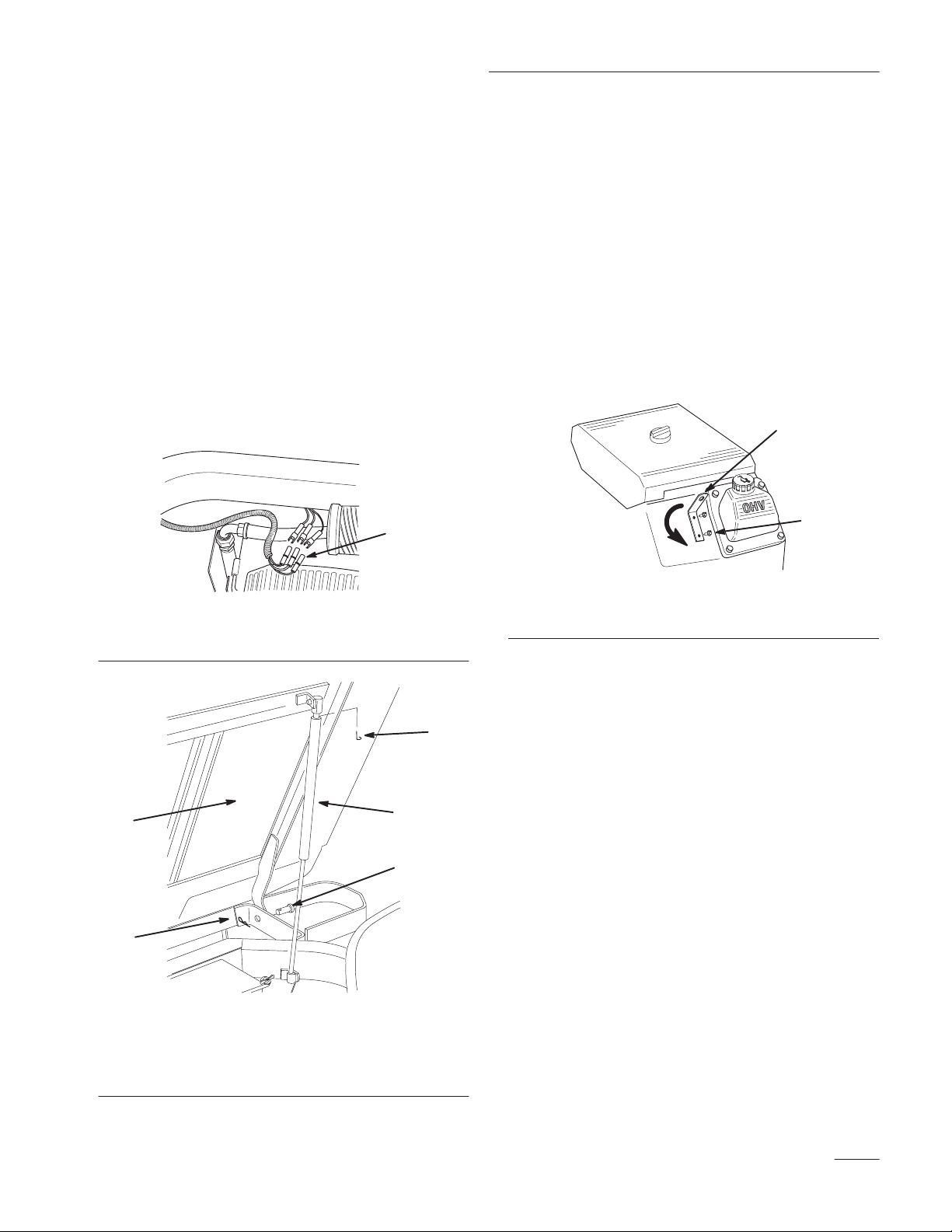
2. Disconnect the wire harnesses along the rear left
side frame as shown in figure 1. Ensure that it is
free of the frame.
3. Remove safety clip from end of gas spring to
hopper. Disconnect gas spring from ball stud
attached to machine frame (Fig. 2). Support
hopper to prevent falling.
4. Lower hopper. Remove both clevis pins from the
rear frame that the hopper pivots on. Remove
hopper. (Fig. 2).
1
M-4582
Figure 1
1. Wire
Harness
Turning
Engine Lift Hook
Turning the engine lift hook will allow clearance for
hose installed later in this instruction sheet. Keep the
hook and hardware for future use if needed.
IMPORTANT: Return lift hook to original
position before it is used for to remove engine.
1. Locate on engine the lift hook in figure 3.
2. Remove the lift hook from engine.
3. Rotate lift hook 180 degrees and reinstall.
1
2
M-4583
Figure 3
1. Engine
Lift Hook
2. Screws
1
4
1. Hopper
2. Safety
3.
Gas Spring
Clip
Figure
2
4.
5.
Hair Pin
Clevis pin
Removing
2
1. Remove all existing air cleaner components
Carburetor
attached to the carburetor. Save the three
mounting screws from the air cleaner base plate
and discard everything else.
3
2. Have an appropriate container ready to catch any
5
remaining fuel that might leak out and
disconnect the fuel line from the carburetor.
3. Follow the red lead from the fuel shut–off
solenoid on the front of the carburetor and
disconnect it from the harness plug.
M-4581
4. Remove and save the two carburetor mounting
screws.
3
Page 4
Installation Instructions
5. Lift and pivot the carburetor to unhook the choke
link, throttle link, and throttle dampening spring
attached to the carburetor. Discard the old
carburetor.
6. Remove the carburetor gasket from the intake
manifold and clean off any remaining material
using an aerosol gasket remover.
IMPORTANT: Do not nick or scratch
manifold surface.
Installing
Carburetor
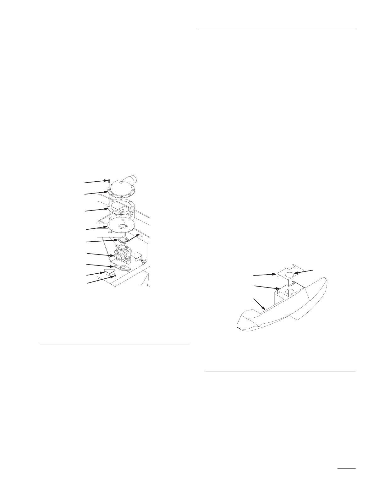
1. Install the two triangular plugs from the kit into
the air ducts on the top of the blower housing.
Start the two thread–forming screws from the kit
into the holes in the front of the air ducts.
Tighten the screws until the plugs are locked into
place (Fig. 5).
2. Install the new carburetor gasket onto the intake
manifold. Make sure all holes are aligned and
open. A dab of gasket adhesive may be used to
keep it in position (Fig. 5).
3. Reconnect the choke link, throttle link, and
throttle dampening spring into the corresponding
levers of the new carburetor (Fig. 5).
6. Check the equipment throttle and choke controls
for proper operation. Be sure the plates in the
carburetor are opening and closing fully with the
movement of the control levers.
7. Connect the lead wire from the fuel shut–off
solenoid.
8. Reconnect the fuel line to the carburetor inlet
and secure with the clamp. Make sure the fuel
line does not interfere with any of the linkages.
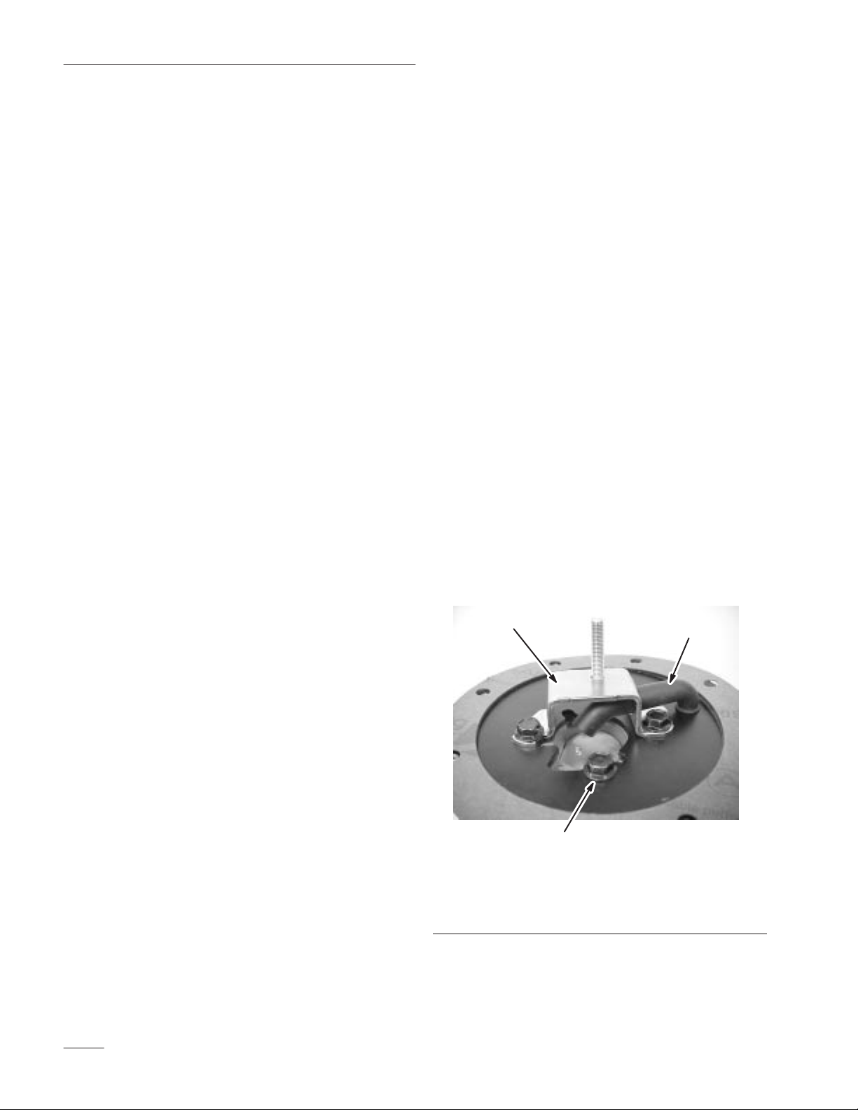
9. Place the new air cleaner base gasket from kit on
top of the carburetor (Fig. 5).
10. Position the new adapter plate over the
carburetor gasket and pull the breather tube
through the corresponding hole until the plate is
seated between the flanges. Assemble the new
air cleaner bracket to the top of the new air
cleaner base, inserting the breather tube through
the hole in side of bracket. Make sure the end of
the breather tube points toward the center of
carburetor throat. Install the three mounting
screws removed in step 1 of Removing
Carburetor, page 3. Torque the screws to
88 in. lb (9.9 N•m). See figure 4.
1
2
4. Set the carburetor into position on the
gasket/intake manifold and install the two
mounting screws saved in step 4 of Removing
Carburetor. Lightly finger tighten the screws
(Fig. 5).
5. Hold the governor lever toward the carburetor as
far as it will go. Check that the throttle plate is
wide open in this position. If the throttle plate is
not wide open, keep pressure against the
governor lever and shift the carburetor until the
plate is wide open. Torque the two mounting
screws to 9.9 NSm (88 in.–lb.).
4
1. Air
Cleaner Bracket
2.
Breather T
ube
3
Figure 4
Mounting Screw
3.
Page 5
Installation Instructions
11. Position the new adapter plate over the
carburetor gasket and pull the breather tube
through the corresponding hole until the plate is
seated between the flanges. The end of the
breather hose must point into the carburetor
throat. Install the three mounting screws
removed in step 1 and torque them to 9.9 NSm
(88 in. lb) (Fig. 5).
12. Position the adapter gasket and air intake adapter
onto the adapter plate, so the hose connection
neck is facing straight back in the engine
compartment. Secure with the seven M6
thread–forming screws. Torque the screws to
10.7 NSm (95 in.–lb.) (Fig. 5).
9
8
7
6
Cutting
Holes in Plastic
Console
A 3I and 3–1/2I diameter hole saw is needed to drill
into the left side plastic console.
Note: Templates 1 and 2 must be used to
locate the correct location for holes.
Templates are located in the back of
this instruction sheet.
1. Locate and cut out templates 1 and 2 from the
back of this instruction sheet.
Note: Do not cut out large circles in paper
templates.
2. Take template number one and fold it across the
fold line.
3. Place template number one onto the top of the
plastic console as shown in figure 6. Tape to
plastic console.
5
4
3
1
2
1. Triangular
2.
Plug Screws
3.
Carburetor gasket
4. Carburetor
5.
Air Cleaner Base Gasket
Plugs
Figure 5
3
6.
Adapter Plate
7.
Adapter Gasket
8.
Air Intake Adapter
9. Screws
M-4571
13. Place rag or tape over air intake adapter opening
to prevent debris entering.
4. Using 3I diameter hole saw, cut a hole at the
specified area in template (Fig. 6).
3
m-4573
Diameter Hole to be cut
Leftside console
1. Template
2. T
emplate Position on
console
1
2
4
#1 (Folded)
Figure 6
3. 3”
4.
5. Locate template number two and cut out small
hole. Fold template at the specified fold lines.
6. Place small cut out hole onto bolt head and place
the fold in the bend of metal support. (Fig. 7).
7. Align diagonal line on template with the edge of
metal support. Tape template to plastic console
and metal support (Fig. 7).
5
Page 6
Installation Instructions
9
8. Mark center of 3–1/2” hole. (Fig. 7).
9. Remove bolt that was used when locating
template position (Fig. 7).
10. Using 3–1/2I diameter hole saw, cut a hole at
the specified area in template (Fig. 7).
11. Reinstall bolt. (Fig. 7).
Note: Part of hole will be cut through metal
support. Remove any burrs from the
metal support after hole is cut.
2
4
1. Template
2. T
console
3–1/2” Diameter Hole to
3.
be cut
4. Bottom
#2 (Folded)
emplate Position on
of Leftside console
5
Figure 7
5. Bolt
Head (Remove bolt
after 3–1/2” hole location
is marked.)
6.
Cut out circle (Align onto
bolt head)
7.
Edge of Metal Support
7
1
3
6
m-457
Drilling
Holes into Bumper
Note: Template 3 must be used to locate the
proper location for holes. Template 3 is
located in the back of this instruction
sheet.
1. Locate and cut out template three from the back
of this instruction sheet.
Note: Do not cut out circles in paper
template.
2. Take template number three and fold it across
the fold line.
3. Place template number three onto the top of the
rear bumper as shown in figure 9. Tape to
bumper.
4. Remove the three bolts as shown in figure 8.
Loosen the fourth bolt but do not remove.
1
4
Note: Figure 7 shows machine as if it were
tipped on its side. Do not tip machine
on its side.
6
1. Bolts
2. Nuts
2
3
Figure 8
3. Bumper
4. Bolt
(Loosen)
m-4580
Page 7

Installation Instructions
5. Rotate the leftside of bumper up to gain access
to drill holes on front leftside of bumper (Fig. 9).
6. Drill two 11/32” holes onto the front of
bumper (Fig. 9). Remove template.
7. Reinstall the bumper to machine frame.
1
4
2
1. Template
2. T
emplate Position on
Bumper
#3 (Folded)
3
Figure 9
1/32” Diameter Holes to
3. 1
be drilled
4.
Leftside of Bumper
m-4574
Installing
Air Cleaner Bracket
1. Align holes in bracket with holes drilled in the
left front of bumper.
2. Install 5/16I bolts into holes and tighten
(Fig. 10).
Note: Install bolts with heads towards the
rear of the machine.
4
3
1. Air
Cleaner Bracket
2. Bolt
Figure 10
3. Nut
4.
Drilled Holes
M-4569
2
1
7
Page 8

Installation Instructions
5
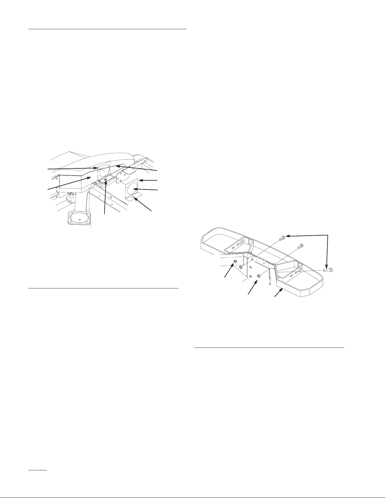
Installing
IMPORTANT:
Air Cleaner
Ther
e are two types of
bumpers. Figure 11 shows the extended
bumper. Figure 12 shows the recessed
bumper.
Refer to #1 in figures 11 and 12 to determine which
type of bumper you have.
IMPORTANT: Ensure you install bolts in the
correct holes in bracket.
1. Install bolts in the correct holes for which type
of bumper you have. Install bolts with heads
towards the top (Fig. 11 or 12).
2. Tighten bolts.
3
1
3
1
5
4
1. Non–Extended
2. Nut
3. Bolt
Bumper
Figure
TOP VIEW
12
4.
Air Cleaner
5.
Front Bracket Holes
1
2
m-4577
5
4
1. Extended
2. Nut
3. Bolt
Bumper
Figure 1
1
TOP VIEW
1
Air Cleaner
4.
5.
Rear Bracket Holes
Installing
Air Intake Hose
1. Install rubber grommet onto hose. (Fig. 13).
Install grommet into console after hose is
clamped down.
2. Locate and insert air intake hose into the bottom
hole of plastic console. (Fig. 13).
2
m-4576
3. Route hose through plastic console and into the
hole cut in top surface.
2
Figure 13
1
Hole cut into bottom of
3.
plastic console
m–457
1. Air
Intake Hose
2. Grommet
3
8
Page 9

Installation Instructions
4. Locate position for R–clamp by measuring down
6” from top of tube and centered on tube. Mark
center of hole in R–clamp (Fig. 14).
5. Drill a 9/32” hole into the tube.
6. Install R–clamp around air intake hose (Fig. 14).
7. Install screw into R–clamp and tube (Fig. 14).
3
5
1
4
2
Figure 14
1. Air
Intake Hose
2. R–Clamp
3.
6 inches
4. Screw
5. Tube
Installing
Flange Connector
1. Install a hose clamp onto end of air intake hose.
Insert flange connector in to intake hose. Tighten
hose clamp (Fig. 15).
2. Insert flange connector and hose into the top
hole in plastic. Center flange connector into the
top hole.
3. Using flange connector as a template, mark and
drill 3/32I pilot holes into plastic console (Fig.
15).
4. Screw 5/16I x 3/4I (19 mm) screws into the
flange connector and plastic console (Fig. 15).
5. Slide air intake hood onto installed flange
connector.
2
1
4
3
7
65
Figure 15
1. Flange
2.
3.
Connector
Air Intake Hood
Hose Clamp
4. Screw
5. Hose
6.
3/32” Pilot Holes
9
Page 10

Installation Instructions
Installing
Hoses to Air Cleaner
1. Install hose clamps on to the ends of the two
hoses.
2. Install the adapter hose and air intake hose onto
the air cleaner canister and tighten the hose
clamps (Fig. 16).
Note: Ensure that air inlet points straight
down. Adjust by loosening bracket
screw. Tighten bracket screw when
adjustment is done.
3. Install the adapter hose onto the air intake
adapter and tighten the hose clamp (Fig. 16).
3
2
2
5
Figure 16
5.
6.
7.
6
Console Hose
Air Inlet
Bracket Screw
4
1. Air
Cleaner
2.
Hose Clamp
3.
Adapter Hose
4.
Air Intake Adapter
2
4. Install rubber grommet onto hose. (Fig. 13).
Install grommet into console after hose is
clamped down.
Installing
Filter Minder
1. Install the Filter Minder Kit to the air cleaner
housing. Use instructions provided in that kit.
IMPORTANT: Do not discard instructions.
Save for future reference and use.
Using Filter Minder
The plunger inside the gauge canister will rise as the
air cleaner becomes dirty and restricted from use. As
it approaches or reaches the “Change Filter” level, air
cleaner maintenance is required.
1. Start by visually checking the condition of the
paper element. If the element is visually dirty,
replace the paper element. Do not attempt to
clean it.
2. Reset the gauge by depressing the button in the
bottom of the canister until the plunger returns to
1
7
the lowest point.
3. Test run the engine and recheck the gauge. If the
plunger remains in the lower ranges, normal
operation can resume. If the plunger returns to
the “Change Filter” level, the paper element is
restricted and must be replaced, even though it
may not appear to be dirty.
4. The gauge may be reset at any time, however it
will return to the prior position if corrective filter
servicing has not been performed.
10
Page 11

Installation Instructions
7
Test
System
1. Reconnect the spark plug leads. Check the
engine oil level.
2. Perform the final carburetor adjustments as
follows.
Note: The new carburetor installed is a ”fixed
jet, emissions certified” carburetor
designed to deliver the correct
fuel–to–air mixture to the engine under
all operating conditions. The fuel
mixtures are set at the factory and
cannot be adjusted.
Installing
Filter Guard
1. Hold guard up to the bumper so the bottom edge
of hole in guard lines up with the bottom edge of
bumper (Fig. 18). Clamp to bumper.
2. Using the guard as a template, drill three 11/32I
holes into bumper (Fig. 18).
3. Install two 5/16” screws into outside holes (Fig.
18). Do not install bolt in center hole until guard
plate is installed.
4. Install the guard plate using a 5/16” bolt in the
center top hole and carriage bolt and wing nut in
the bottom hole (Fig. 18).
4
2
1
1. Low
Idle Speed Adjusting
Screw
1
Figure 17
m–4540
3. Start the engine and check to be certain that oil
pressure (20 psi or more) is present. Run the
engine for 5–10 minutes to warm up. The engine
must be warm before making final settings.
4. Place the throttle control into the ”idle” or
”slow” position. Turn the low idle speed
adjusting screw in or out, to obtain a low idle
speed of 1400 RPM (±75 RPM). Check the
speed using a tachometer (Fig. 17).
5. Move the throttle control to the
”Fast/Full–Throttle” position. Using a
tachometer, check that the maximum engine
speed does not exceed 3250 RPM (±50 RPM).
Adjust if necessary.
2
1. Align
2. 1
3. Guard
4. Bolt
Bottom Edges
1/32” Holes to drill
4
4
4
3
8
Figure 18
5. Nut
6.
7.
8.
6
Carriage Bolt
Guard Plate
Wing Nut
11
Page 12

Installation Instructions
Servicing
the Air Cleaner
Primary Filter: Clean or replace every 200 operating
hours.
Safety Filter: Replace after every 600 operating
hours.
Note: Service the air cleaner more frequently
if operating conditions are extremely
dusty or sandy.
Removing the Filter
1. Disengage the power take off (PTO), set the
parking brake, and turn the ignition key to
“OFF” to stop the engine. Remove the key.
Remove spark plug wire(s) and remove the key.
2. Release the latches on the air cleaner and pull the
air cleaner cover off of the air cleaner body
(Fig. 19).
3. Clean the inside of the air cleaner cover with
compressed air
.
m–4387
1. Latches
2. Air
cleaner cover
3.
Air filter body
5
2
Figure 19
4.
5.
3
4
1
Primary filter
Safety filter
1
Cleaning the Primary Filter
Blow compressed air from the inside to the outside of
the primary filter.
IMPORTANT: Do not exceed 100 psi and
keep the hose at least 2 inches from the filter.
4. Gently slide the primary filter out of the air
cleaner body (Fig. 19). Avoid knocking the
filter into the side of the body. Do not remove
the safety filter, unless you intend to replace it as
well.
5. Inspect the primary filter for damage by looking
into the filter while shining a bright light on the
outside of the filter. Holes in the filter will
appear as bright spots. If the filter is damaged,
discard it, otherwise clean it.
IMPORTANT: Never attempt to clean the
safety filter. If the safety filter is dirty, then
the primary filter is damaged and you should
replace both filters.
Installing the Filters
1. If installing new filters, check each filter for
shipping damage. Do not use a damaged filter.
2. If the safety filter is being replaced, carefully
slide it into the filter body (Fig. 19).
3. Carefully slide the primary filter over the safety
filter (Fig. 19). Ensure that it is fully seated by
pushing on the outer rim of the filter while
installing it.
IMPORTANT: Do not press on the soft inside
area of the filter.
4. Install the air cleaner cover with the side
indicated as UP facing up and secure the latches
(Fig. 19).
12
Page 13

Installation Instructions
3I DIA. Hole
Template
Do Not cut out
this circle in
paper template.
#1
Fold Line
13
Page 14

Installation Instructions
14
Page 15

Installation Instructions
3–1/2I
DIA.
Template
Align
support edge.
Hole
Do Not cut out
circle in paper
template.
#2
with metal
Cut
Out
Fold Lines
15
Page 16

Installation Instructions
16
Page 17

Installation Instructions
Align to
edge of
bumper
Template
Fold Line
#3
Do Not cut out
these circles in
paper template.
17
Page 18

Installation Instructions
18
Page 19

Installation Instructions
19
Page 20

Installation Instructions
20
 Loading...