

Page 1
52” Pulley Kit
For Z–Master Series
FORM NO. 3322-688
Part No. 100–2317
Loose
Note: Use the chart below to identify parts for assembly.
DESCRIPTION QTY. USE
Pulley Assembly
Belt
Idler Arm
Flat W
Removing
1. Stop the engine, set the parking brake, remove
2. Remove the clutch retaining strap from machine
3. Remove the PTO drive belt (Fig. 4).
4. Loosen idler pulley on deck belt. Remove deck
Parts
ashers
Belts
the key and disconnect the spark plug wire(s)
from the spark plug(s).
frame and unplug clutch terminal from wire
harness (Fig. 4).
belt from center spindle pulley.
1
1
1
2
Install Pulleys
Install Idler Arm
Installing
Note: Clean area around pulley before
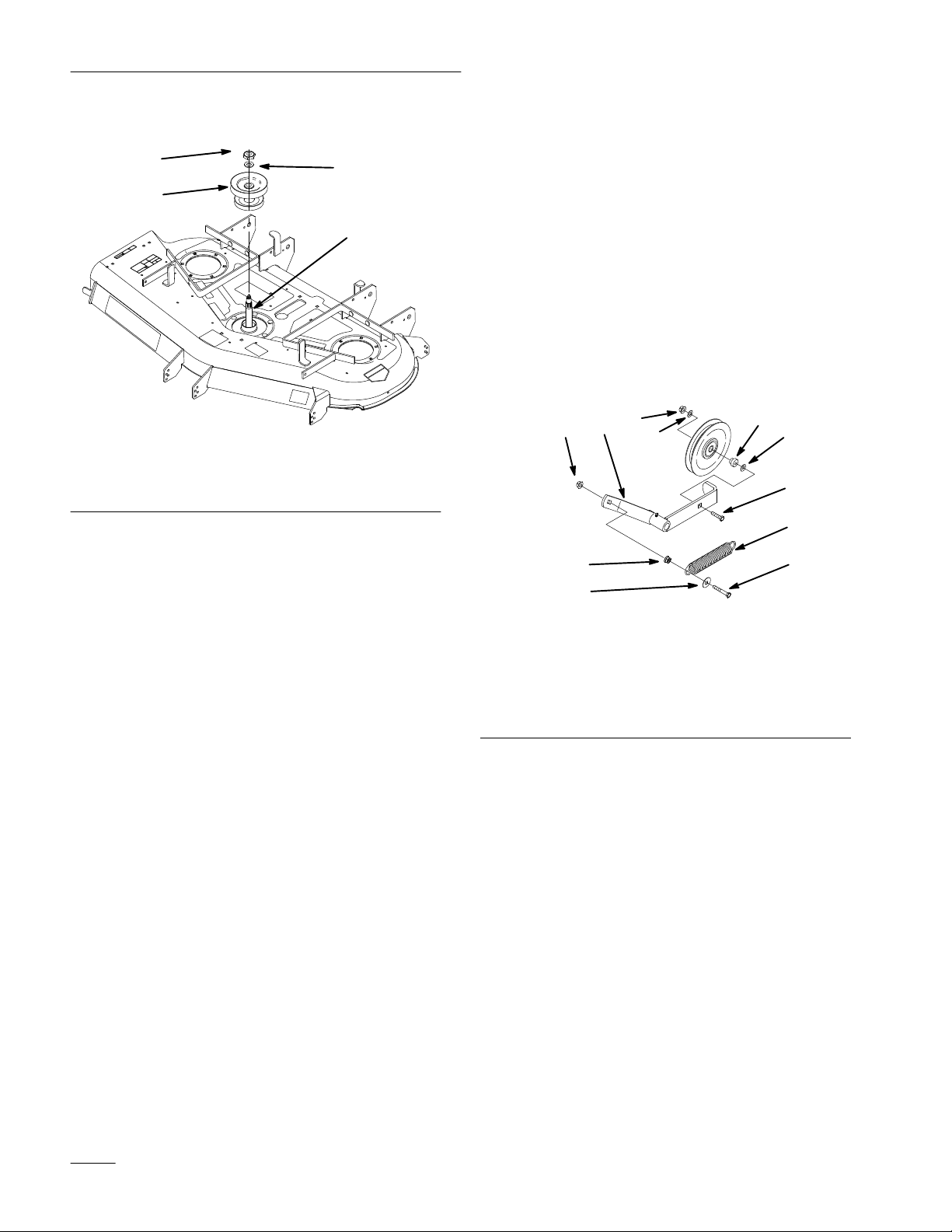
1. Remove nut and washer on top of center spindle
(Fig. 1). Save the nut and washer.
2. Remove existing pulley assembly (Fig. 1).
3.
Install new pulley assembly. Install it so the
large pulley is on top (Fig. 1).
Pulleys
removing pulley assembly. Hold
spindle up from underneath deck. It
can fall when nut and washer are
removed.
INSTALLATION
INSTRUCTIONS
Printed in USA
The T
oro Company – 1999
All Rights Reserved
4. Reinstall washer and nut. Torque nut to 115
ft–lbs (156 Nm) (Fig. 1).
Page 2
Installation Instructions
5.
Grease spindle.
Installing
New Drive Belt Idler
1
3
1. Nut.
2. Washer
Removing
Figure 1
3. Pulley
4. Spindle
Old Drive Belt Idler
2
4
Assembly
Arm
1. Remove the spring from the old idler arm (Old
idler arm not shown) (Fig. 3).
2. Remove the old idler arm from the machine
frame (Old idler arm not shown) (Fig. 3).
Arm
1. Route new belt onto the idler pulley. Install
pulley and belt to new idler arm using existing
hardware (Fig. 2).
2. Install spring to new idler arm. Use existing
hardware and new flat washer included in kit.
(Fig. 2).
Note: New flat washer must be installed
between spring and heat of bolt.
7
6
9
4
5
asher
1. New
2.
3.
4. Spring
5.
Idler Arm
Lock Nut
New Flat W
Bolt (3/8”–16 x 2–1/4”)
asher
2
3
122
6
Figure 2
6.
Flat W
7. Bushing
8.
Idler Pulley
9.
Bolt (3/8”–16 x 1–3/4”)
3. Remove the spring from the machine frame.
Discard old washer (Fig. 3).
4. Remove the pulley, bushing, and hardware from
idler arm. (Old idler arm not shown) (Fig. 2).
2
3. Install new idler arm assembly to machine
frame. Use existing hardware to attach it (Fig.
3).
4. Install spring to machine frame. Use existing
hardware and new flat washer included in kit.
(Fig. 3).
Page 3

Installation Instructions
Note: New flat washer must be installed
between spring and heat of bolt. The
spring must be installed between new
flat washer and spacer (Fig. 3).
8
4
5
1
1. Idler
2.
3.
4.
5.
Arm
Lock Nut
New Flat W
Bolt (3/8”–16 x 3–1/2”)
Flat W
asher
asher
9
376
Figure 3
6. Spacer
Nylon Locknut
7.
8.
Bolt (3/8”–16 x 2–1/4”)
9. Bushing
M-4416
Installing
belts
1. Place deck belt onto new pulley assembly. Route
belt onto outer pulleys and idler pulley.
2. Place new PTO drive belt over clutch, around
rear idler pulley, installed into idler arm
assembly and onto mower top center pulley.
2
Note: Check that belt has only 1/4 twist
between each pulley and idler.
3. Install clutch retaining strap and plug clutch
terminal into main wire harness (Fig. 4).
4
5
3
m–3748
1
2
Figure 4
1. Clutch
2. Clutch
3.
Clutch T
retaining strap
erminal
4. PT
O belt
5.
Machine Frame
4. Check belt tension. The center bolt of spring
loaded idler must be between the two alignment
holes in left support plate (Fig 5).
M-4373
3
Page 4

Installation Instructions
8. To adjust push arms, remove PTO drive belt,
loosen jam nut and rotate ball joint
counterclockwise, one turn at a time. Adjust
each side the same amount (Fig. 7).
2
push arms and decrease tension by
shortening push arms.
Note: Increase tension by lengthening the
3
1
M-4417
1
Figure 5
1. Center
idler
bolt, spring loaded
2.
Alignment hole
5. If adjustment is required, loosen the fixed idler
on right support plate and move up or down in
adjustment slot. To relieve belt tension lift up on
spring loaded idler (Fig. 6).
1. Push
2.
12
Adjusting
arm
15” (381 mm) nominal
Belt Guides
Figure 7
3.
4.
1
2
m–3740
Jam nut
Ball joint
Figure 6
1. Fixed
Idler
2.
Adjustment slot
6. Check belt tension again. The center bolt of
spring loaded idler must be between the two
alignment holes in left support plate (Fig 5).
Adjust, if necessary, and tighten all hardware
securely.
7. If the fixed idler contacts the end of the
adjustment slot and more belt tension is
required, a small change in the length of the
push arms can be made (Fig. 7).
m–3746
1. Loosen belt guide (Fig. 8).
2. Rotate the belt guide, on rear of the mower, so it
is 1/8”–1/4” (3–7 mm) away from the vertical
side of the PTO belt (Fig. 8).
1
3
1. Belt
2. PT
guide
O Drive belt
Figure 8
3.
1/8”–1/4” (3–7 mm)
2
M-4399
4
 Loading...