

Page 1
36” Tiller Lift Cable Kit
FORM NO. 3322–562 Rev. A
INSTALLATION
INSTRUCTIONS
Loose
Parts
PART
NO. 100–1591
Note: Use the chart below to identify parts used for assembly.
DESCRIPTION QTY. USE
Cable guide
Cable
Guard extension
Installation Instructions
1
1
2
1
Installation of kit
Read before installing
Description
This kit is designed for use on tillers, Model No.
79375 and Model No. 715704006, to prevent the lift
cable from interfering with the transaxle cooling fan.
In addition, guard extensions are provided to prevent
lift bar interference with the jack shaft pulley.
3
Installing
the Lift Cable
1. If the tiller is mounted on a tractor, park the unit
on a level surface and lower the tiller to the
ground. Turn the ignition to “STOP” to stop the
engine. Remove the ignition key.
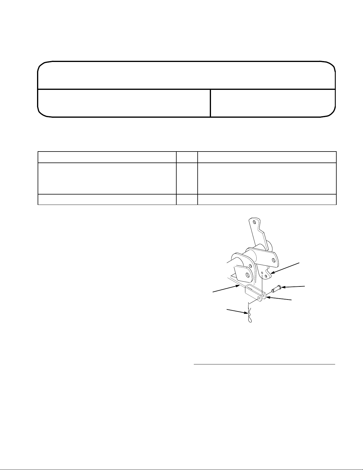
2. Remove the hairpin and clevis pin from the lift
cable at the attachment lift arm (Fig. 1).
Note: Attachment lift arm may be different
than shown in Fig. 1 on some models.
1
1. Lift
cable
2. Clevis
3.
Attachment lift arm
4
2
5
m–3504
Figure 1
4.
Clevis pin 5/16” x 1” (25
mm)
5.
Hairpin cotter
Page 2
Installation
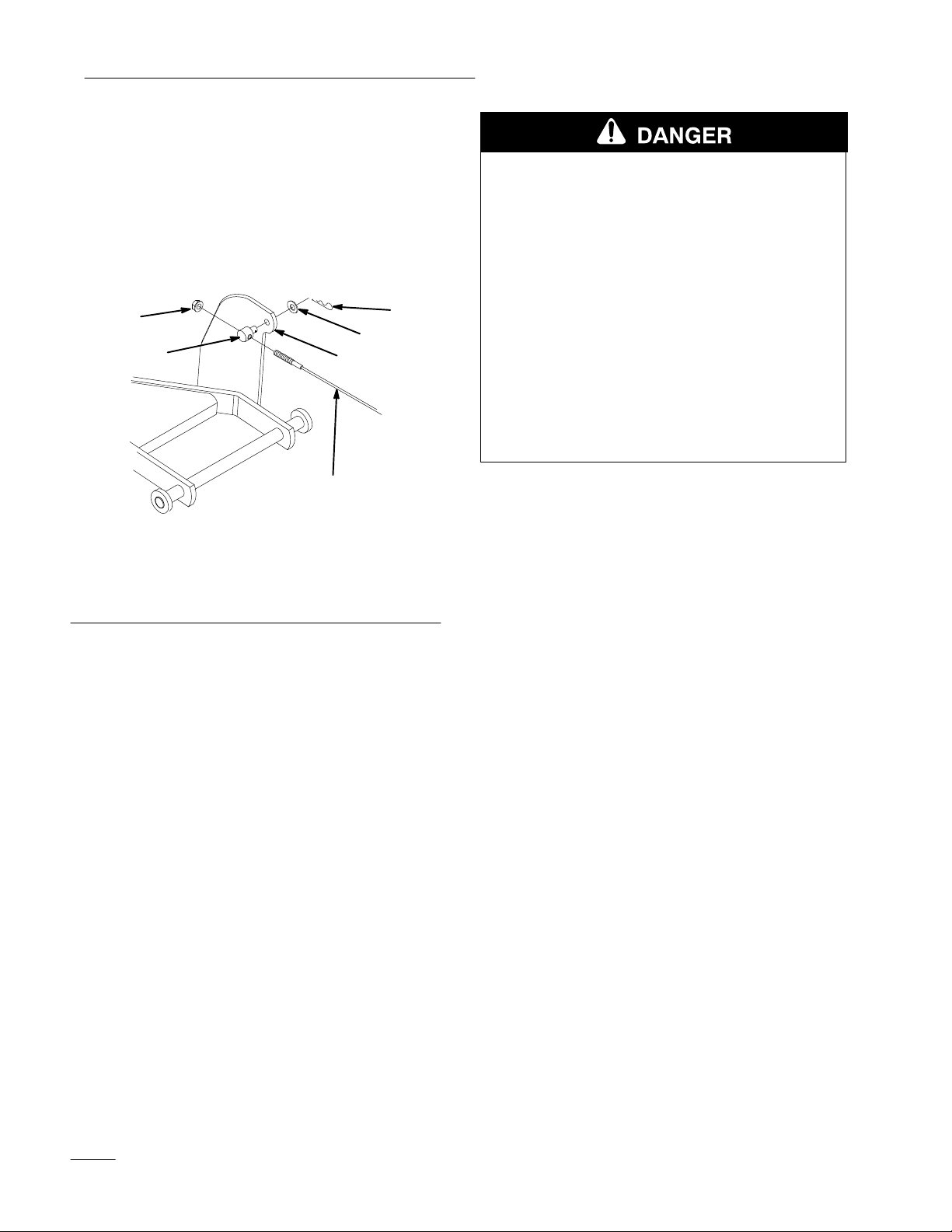
3. Remove the hairpin, washer and trunnion from
the tiller lift mounting bracket on the tiller.
Remove the trunnion and cable assembly
(Fig. 2). Measure and record the distance from
the end of the cable to the trunnion to use as a
reference for installing the trunnion on the new
cable. Unscrew the locknut and trunnion from
the lift cable. Save all parts except the lift cable.
3
2
6
4
5
POTENTIAL HAZARD
• Rotating shaft or cooling fan can cause
injury.
WHAT CAN HAPPEN
• Fingers, hands, feet, hair, etc. can get
caught by shaft or fan.
• Loose clothing can get caught by shaft.
HOW TO AV
OID THE HAZARD
• Do not operate the tractor without the drive
shaft cover in place.
• Keep hands and arms clear of rotating
shaft or fan.
1
m–3503
Figure 2
1. Lift
cable
2. Trunnion
3. Locknut
Installing
the Cable Guide
4. Hairpin
5.
Flat washer
6. T
iller lift mounting bracket
The cable guide can be installed from the underside
of the tractor. For more visibilty, the drive shaft
maintenance cover can be removed to aid in
installation.
1. Remove the two bolts in the plastic fan baffle
(Fig. 3) and remove the baffle.
2. Remove the clip nut from the left side of the
plastic fan baffle and install over the hole in the
bent tab of the cable guide (Fig. 3).
3. Remove the nut from the pivot bolt on the left
hand attachment lift arm (Fig. 3). Leave the bolt
in place.
4. Install the rear hole of the cable guide to the left
hand lift arm pivot bolt and replace the nut
loosely (Fig. 3).
5. Reinstall the plastic fan baffle with one of the
previously removed bolts in the right hand side
only (Fig. 3). Leave the bolt loose.
2
Page 3

Installation Instructions
6. Align the front of the cable guide with the hole
in the left hand side of the plastic fan baffle and
reinstall the other bolt previously removed.
Tighten all bolts and nuts securely.
1
9
8
7
4
2
5
3
3. Replace the drive shaft maintenance cover if it
was removed
Installing
the Guard
Extensions
1. Remove the jack shaft assembly from the tractor,
if installed.
2. Place a guard extension on the top forward edge
of each of the two existing guards (Fig. 4).
Clamp each guard extension tight against the
existing guard and weld in place.
1
2
6
Figure 3
1. Cable
2.
3.
4. Left
5. Plastic
Installing
guide
Clip nut
Fan baf
fle bolt
hand lift arm pivot bolt
nut
fan baf
fle
the New Lift Cable
6.
Right hand attachment lift
arm
7.
Rear of tractor
8.
Pivot bolt
9.
Lift cable
1. Install the trunnion and locknut on the new cable
provided in the kit. Use the measurement taken
in step 3 (Removing the Lift Cable), for locating
the trunnion. Reinstall the trunnion into the
tiller lift mounting bracket using the flat washer
and hairpin previously removed (Fig. 2).
2. Attach the lift cable clevis to the tractor’s
attachment lift arm, as previously installed
(Fig. 1), using the hairpin and clevis pin from
the original installation.
4
3
5
m–4405
Figure 4
1. Guard
2.
3. W
extensions
Existing guards
eld areas
4.
Front of tractor
5.
Jack shaft assembly
3. Add touch–up paint to the welded area when
installation is complete.
3
Page 4

Installation
4
 Loading...