

Page 1
FormNo.3368-805RevC
ProCoreSR48,SR54,SR54–S,
SR70,SR70–S,SR72andSR75
Aerators
ModelNo.09930—SerialNo.311000001andUp
ModelNo.09931—SerialNo.311000001andUp
ModelNo.09932—SerialNo.311000001andUp
ModelNo.09933—SerialNo.311000001andUp
ModelNo.09934—SerialNo.311000001andUp
ModelNo.09935—SerialNo.311000001andUp
ModelNo.09936—SerialNo.311000001andUp
ToregisteryourproductordownloadanOperator'sManualorPartsCatalogatnocharge,gotowww.Toro.com.OriginalInstructions(EN)
Page 2
Introduction
Readthisinformationcarefullytolearnhowtooperate
andmaintainyourproductproperlyandtoavoidinjury
andproductdamage.Youareresponsibleforoperating
theproductproperlyandsafely.
YoumaycontactTorodirectlyatwww .Toro.comfor
productandaccessoryinformation,helpndingadealer,
ortoregisteryourproduct.
Wheneveryouneedservice,genuineToroparts,
oradditionalinformation,contactanAuthorized
ServiceDealerorToroCustomerServiceandhave
themodelandserialnumbersofyourproductready .
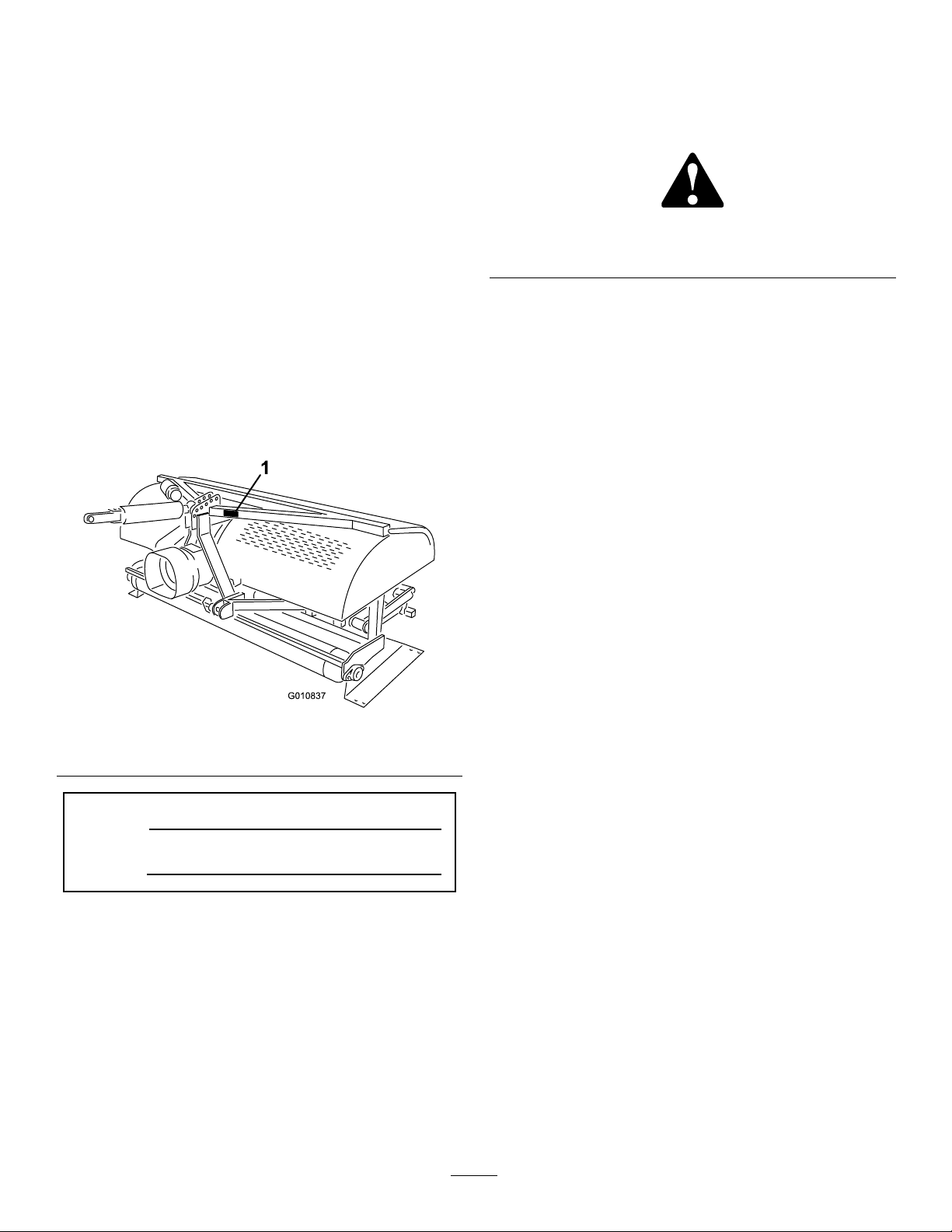
Figure1identiesthelocationofthemodelandserial
numbersontheproduct.Writethenumbersinthe
spaceprovided.
Thismanualidentiespotentialhazardsandhassafety
messagesidentiedbythesafetyalertsymbol(Figure2),
whichsignalsahazardthatmaycauseseriousinjury
ordeathifyoudonotfollowtherecommended
precautions.
Figure2
1.Safetyalertsymbol
Thismanualuses2otherwordstohighlightinformation.
Importantcallsattentiontospecialmechanical
informationandNoteemphasizesgeneralinformation
worthyofspecialattention.
1.Modelandserialnumberlocation
ModelNo.
SerialNo.
©2011—TheToro®Company
8111LyndaleAvenueSouth
Bloomington,MN55420
Figure1
Contactusatwww.Toro.com.
2
PrintedintheUSA.
AllRightsReserved
Page 3

Contents
Introduction.................................................................2
Safety...........................................................................4
SafeOperatingPractices.......................................4
SafetyandInstructionalDecals.............................6
Setup...........................................................................8
1RemovingtheAeratorfromtheCrating..............9
2ConnectingtheLowerLinkArms......................9
3ConnectingtheHydraulicTopLink
(ModelsSR48,SR54,SR70,SR72and
SR75).............................................................10
4ConnectingtheTractorUpperLink(Models
SR54–SandSR70–S)......................................12
5VerifyingtheHydraulicTopLinkSet
Up..................................................................12
6CheckingthePTOAngle.................................13
7FittingthePTOshaft.......................................14
8InstallingthePTOShield.................................15
9ConnectingthePTOShaft...............................16
10AdjustingtheSwayLinks................................17
11LevelingtheAeratorSide-to-Side...................18
12InstallingtheTines.........................................18
13SettingtheTineDepth(ModelsSR54–S
andSR70–S)...................................................18
14InstallingtheRearGuard................................19
15InstallingtheLatchLock................................20
16RemovingtheStorageStands(ModelsSR54
andSR70)......................................................20
17RemovingtheStorageStands(ModelsSR48
andSR72).......................................................21
ProductOverview......................................................22
Specications.....................................................22
Attachments/Accessories...................................22
Operation...................................................................23
TractorControls.................................................23
PrinciplesofOperation......................................23
TractorPTOSpeed............................................23
TrainingPeriod...................................................23
BeforeAerating..................................................23
AeratingProcedures...........................................24
OperatingTips...................................................24
SubsoilCultivation.............................................25
HardGround.....................................................25
Longer/LargerTines..........................................25
MultiRowAdapterHeads..................................25
RootZoneLifting..............................................25
UsingtheHoodPropRodsModelSR75
only................................................................25
AdjustingtheTineAngle....................................26
AdjustingtheTineDepth(ModelsSR54–S
andSR70–S)...................................................27
TransportOperation..........................................27
InspectionandCleanupafterUse........................28
Maintenance...............................................................29
RecommendedMaintenanceSchedule(s)................29
LiftingtheMachine............................................29
GreasingtheBearings.........................................30
CheckingtheGearboxOil..................................30
ChangingtheGearboxOil..................................31
Inspecting/AdjustingtheDriveChain................31
AdjustingthePTOClutch..................................32
FastenerTorqueSpecications............................32
CheckingtheSprings..........................................33
AdjustingtheHoleSpacing.................................33
RemovingtheAeratorfromtheTractor...............33
TroubleShooting...............................................34
Storage.......................................................................35
3
Page 4

Safety
Improperuseormaintenancebytheoperatoror
ownercanresultininjury.Toreducethepotential
forinjury,complywiththesesafetyinstructions
andalwayspayattentiontothesafetyalert
symbol,whichmeansCAUTION,WARNING,or
DANGER-"personalsafetyinstruction."Failureto
complywiththeinstructionmayresultinpersonal
injuryordeath.
SafeOperatingPractices
BeforeOperating
•OwnersofthisAeratormustgiveoperatorsand
employeesfulloperationandsafetyinstructions
beforeallowingthemtooperatethismachineandat
leastannuallythereafter.Anoperatorwhohasnot
readandfullyunderstoodalloperatingandsafety
instructionsisnotqualiedtooperatethismachine.
Becomefamiliarwithallcontrolsandknowhowto
stopquickly.
•Donotallowchildrentooperatethemachine.Do
notallowadultstooperatethemachinewithout
properinstruction.
•Removealldebrisorotherobjectsthatmight
interferewithoperation.Keepallbystandersaway
fromtheworkarea.
•Locateandmarkallundergroundobstructionssuch
asirrigationcomponents,electricalortelephone
lines.
•Makesuretractorisinneutralandparkingbrake
appliedbeforestarting.RefertoTractorOperator's
Manualforsafestartingprocedures.
•Ensurethatyourtractorissuitableforusewithan
implementofthisweightbycheckingwithyour
tractorsupplierormanufacturer.
•Mountingtheaeratortotherearofthetractorwill
decreasetheweightonthetractorfrontaxle.To
assureadequatesteeringcontrolandstabilityitmay
benecessarytoaddballasttothefrontofthetractor.
RefertoTractorOperator'sManualforballast
requirements.
•Keepallshieldsandsafetydevicesinplace.Ifa
shield,safetydeviceordecalisdamaged,repairor
replaceitbeforeoperationiscommenced.Also
tightenanyloosenuts,boltsandscrewstoensure
machineisinsafeoperatingcondition.
•Donotoperatemachinewhilewearingsandals,
tennisshoes,sneakersorshorts.Also,donotwear
loosettingclothingwhichcouldgetcaughtin
movingparts.Alwayswearlongpantsandsubstantial
shoes.W earingsafetyglasses,safetyshoes,hearing
protectionandahelmetisadvisableandmaybe
requiredbysomelocalordinancesandinsurance
regulations.
WhileOperating
•Neveroperatethetractorinreversewhentheaerator
islowered.
•Keepallbystandersandpetsawayfromthework
area.
•Usingthemachinedemandsattention,andto
preventlossofcontrol:
–Useonlyindaylightorwhenthereisadequate
articiallight.
–Watchforholesorotherhiddenhazards.
–Donotoperatethemachineclosetoasandtrap,
ditch,creekorotherhazard.
–Reducespeedonsidehillsandbeforemaking
sharpturnstopreventtippingorlossofcontrol.
–Lookbehindtheaeratorbeforebackingup.
•Ifthetinesstrikeasolidobjectorthemachine
vibratesabnormally,disengagethePTO ,setthe
parkingbrakeandshuttheengineoff.Removekey
fromignitionswitch.Checkaeratorandtractionunit
fordamage.Repairanydamagebeforerestartingthe
engineandoperatingthetines.Besuretinesarein
goodconditionandallboltsaretight.
•Beforeleavingmachineunattended,disengagepower
toaerator,loweraeratorontostoragestandsandset
parkingbrake.Stopengine.
•Neverdismountwhiletractorisinmotion.Never
getonorofftractorwhileengineisrunningand
PTOdriveshaftisengaged.NeverstepoverPTO
shafttoreachothersideofaerator-walkaround
themachine.
•Whenliftingtheaerator,disengagethePTOwhen
therollerisapproximately5inchesfromtheground.
•Donotoperatethismachinewithouttherolleron
theground.Neveroperatewiththemachinein
theraisedposition.
•Parktheaeratoronahard,levelsurface,installthe
aeratorstoragestandsbeforedisconnectingfrom
tractor.
•Ifitisnecessarytoprobebelowthesoilsurface,use
anonconductivematerialtopreventelectricalshock
incaseelectricalwiresarepresent.
•Alwayslowertheaeratortothegroundbefore
leavingthetractorunattended.Neverleavethe
aeratorintheraisedpositionwhenitisunattended.
4
Page 5

Transporting
•Theaeratorisheavy.Whenattachedtoatractor
andintheraisedposition,itsweightwillaffect
stability,brakingandsteering.Exercisecautionwhen
transportingbetweenworkingareas.
•Alwaysmaintainpropertractortirepressure.
•Besureyouareincompliancewithallregulations
beforetransportingequipmentonthepublicroads
andhighways.Makesureallrequiredreectors
andlightsareinplaceandarecleanandvisibleby
overtakingandoncomingtrafc.
•Neverallowpassengerstorideonthemachine
duringtransport.
•Reducespeedonroughroadsandsurfaces
•Independentwheelbrakesshouldalwaysbelocked
togetherwhentransporting.
PTOShaft
•ForallPTOshaftsteelparts(tubes,bearings,joints
etc.)disassemblyorrepairs,itishighlyadvisable
tocontactyourlocalTorodistributor.Removalof
componentsforrepairsandreassemblymaydamage
somepartsifnotperformedwithspecialtoolsby
trainedtechnicians.
•ThePTOshaftmustnotbeusedwithouttheguards
supplied,withpartialprotectionorwithdamaged
guards.OnCEmachines,operationisprohibited
withoutthespecialanti-rotationchainscorrectly
installed,soastopermitthemaximumangleofthe
PTOshaftwithoutbreakingthechains.
•Besurethemachineisinsafeoperatingconditionby
keepingnuts,boltsandscrewstight.Checkthetine
mountingboltsdailytobesuretheyaretightened
tospecication.
•Donotcheckoradjustthechaintensionwhenthe
tractorengineisrunning.
•Besureallguardsarereplacedandthehoodis
securedshutaftermaintainingoradjustingthe
machine.
•Performonlythosemaintenanceinstructions
describedinthismanual.Ifmajorrepairsare
everneededorassistanceisdesired,contactan
AuthorizedToroDistributor.Toensureoptimum
performanceandsafety,alwayspurchasegenuine
Tororeplacementpartsandaccessoriestokeepthe
ToroallT oro.Neveruse"will-t"replacementparts
andaccessoriesmadebyothermanufacturers.Look
fortheTorologotoensuregenuineness.Using
unapprovedreplacementpartsandaccessoriescould
voidthewarrantyofTheToroCompany .
StorageSafety
•Storetheaeratoronthestoragestandspositionedon
armlevelsurface.
•Storetheaeratorawayfromareasofhumanactivity.
•Donotallowchildrentoplayonoraroundthe
storedmachine.
•Makesuretheaeratorispositionedonrmandsolid
groundsoitdoesnotsinkortipover.
•Frictionclutchesmaybecomehotduringuse.Do
nottouch.Toavoidtheriskofre,keepthearea
aroundtheclutchfreeofammablematerialand
avoidprolongedslippingoftheclutch.
Maintenance
•Beforemakingadjustmentsorperforming
maintenanceontheaerator,switchofftheengine,
stopthePTOandapplytheparkingbrakebefore
dismountingfromthetractor.Besuretheaeratoris
onthegroundorloweredontothesafetystands.
•Supportthemachinewiththeblocks,jacksoron
storagestandswhenworkingbeneathit.Never
relyonthetractor'shydraulicstosupportthe
machine.
•Placeallcontrolsinneutral,stoptheengine,apply
parkingbrakeandwaitforallmovingpartsto
stopbeforeservicing,maintaining,adjustingor
unblockingtheaerator.
5
Page 6
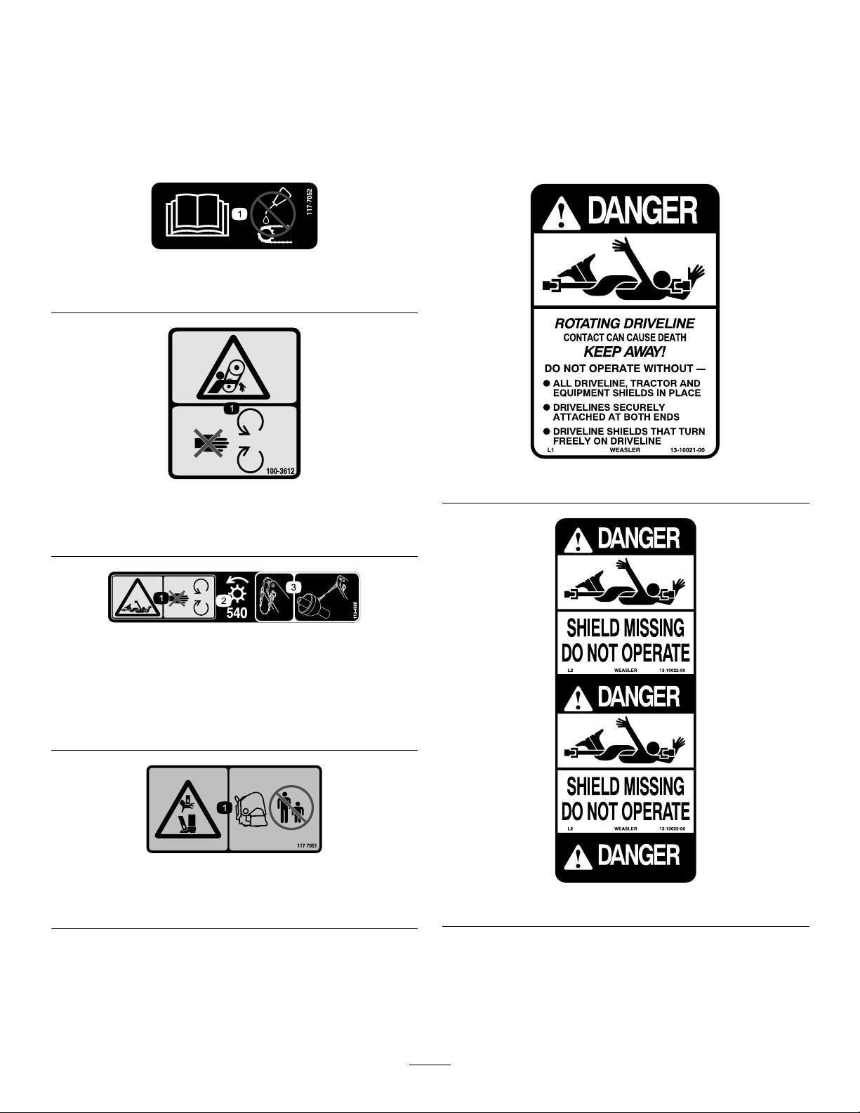
SafetyandInstructionalDecals
Safetydecalsandinstructionsareeasilyvisibletotheoperatorandarelocatednearanyareaof
potentialdanger.Replaceanydecalthatisdamagedorlost.
117–7052
1.ReadtheOperator’sManual,donotoilthechaindrive.
100–3612
1.Entanglementhazard—stayawayfrommovingparts,keep
allguardsandshieldsinplace.
110-4668
1.Entanglementhazard,shaft—stayawayfrommovingparts.
2.PTOspeedandinputdirection.
3.Usecliptosecurelashcablewhennotinuse.Uselash
cabletosupportthepowertake-offwhenthemachineis
disconnectedfromtractor.
117–7051
92–1581
1.Crushinghazardofhandorfoot—keepbystandersasafe
distancefromthemachine.
92–1582
6
Page 7
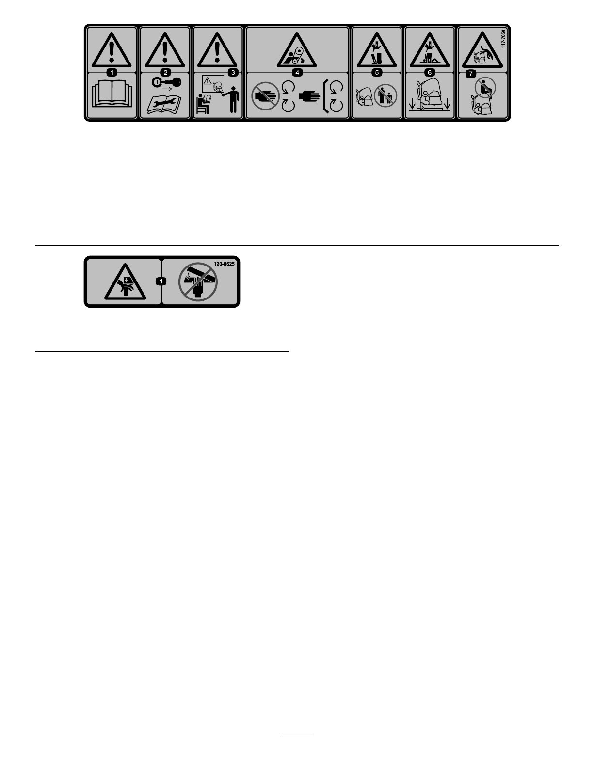
117–7050
1.Warning—readtheOperator'sManual.
2.Warning—removetheignitionkeyandreadtheinstructionsbeforeservicingorperformingmaintenance.
3.Warning—donotoperatethismachineunlessyouaretrained.
4.Entanglementhazard,belt—stayawayfrommovingparts,keepallguardsinplace.
5.Crushinghazardofhandorfoot—keepbystandersasafedistancefromthemachine.
6.Crushinghazardofhandandbody—supportmachineonstandwhennotinuse.
7.Fallinghazard—donotcarrypassengers.
120-0625
1.Pinchpoint,hand—keephandsaway.
7
Page 8

Setup
LooseParts
Usethechartbelowtoverifythatallpartshavebeenshipped.
ProcedureDescription
1
2
3
4
5
6
7
Nopartsrequired
Hitchpin2
Lynchpin2
Hydraulictoplink1
Hydraulichose,3–1/2feet
Hydraulichose,2–1/2feet
Extensionbracket2
Rotationalbracket1
Hosequickcouplings2
Springloadedtoplink
Linkpin3
Lynchpin3
Nopartsrequired
Nopartsrequired
PTOshaft
Qty.
Use
–
1
1
1
–
–
1
Removetheaeratorfromthecrating
Connectlowerlinkarms(Hitchpinsand
lynchpinsareshippedinstalledonthe
SR54andSR54-SAerators)
ConnectHydraulicT opLink(Models
SR48,SR54,SR70,SR72andSR75)
ConnectUpperLink(ModelsSR54–S
andSR70–S)
Verifythetoplinksetup
CheckingthePTOangle
FittingthePTOshaft
8
9
10
11
12
13
14
15
16
PTOShield
Pin(suppliedwithPTOshaft)
Nut(suppliedwithPTOshaft)
Nopartsrequired
Level(notsupplied)
Tines
Nopartsrequired
Rearguard1
Screw,3/8x3–1/4inch
Flatwasher,.438x1.00inch12
Locknut4
Endcap2
Lockplate2
Tapbolt2
Retainingring2
Nopartsrequired
1
1
1
–
1
A/R
–
4
–
InstallthePTOShield
ConnectPTOShaft
AdjustingSwayLinks
LevelAeratorSide-to-Side
InstalltheTines
Setthetinedepth
Installtherearguard
Installthelatchlock
RemoveStorageStands
17
Nopartsrequired
8
–
RemoveStorageStands
Page 9
MediaandAdditionalParts
Operator'sManual
PartsCatalog
SpringWires-SR48
SpringWires-SR48
SpringWires-SR54&SR54-S
SpringWires-SR70&SR70-S
SpringWires-SR72
SpringWires-SR72
SpringWires-SR75
SpringWires-SR75
Operatortrainingmaterials
PTOOperatorsManual
Description
Qty.
1
1
4Replacementspringwires
2Replacementspringwires
6Replacementspringwires
8Replacementspringwires
4Replacementspringwires
2Replacementspringwires
4Replacementspringwires
2Replacementspringwires
1
1
Readbeforeoperatingtheaerator
Usetoreferencepartnumbers
Viewbeforeoperatingtheaerator
Readbeforeoperatingtheaerator
Use
1
RemovingtheAeratorfrom
theCrating
NoPartsRequired
Procedure
1.Removetheaeratorfromthecrating.
2.Removetheboltssecuringtheaeratorstoragestands
totheshippingpalletandremovetheaeratorfrom
thepallet.
3.Removethestoragestandsfromtheaerator.Retain
themforstorageuse.
Note:TheSR54-SandtheSR70-Sdonothave
shippingstands.
4.Placetheaeratoronaat,levelsurfacewiththe
frontrolleronthegroundanda2x4positioned
undertheheads.
2
ConnectingtheLowerLink
Arms
Partsneededforthisprocedure:
2Hitchpin
2Lynchpin
Procedure
1.Backthetractorsquarelyuptotheaeratoruntil
thelowerlinkarmsarealignedwiththemounting
brackets.
Note:Theaeratorgearboxshaftshouldbeinline
withthetractorPTOshaft(centeredonthetractor).
Iftheyarenotinline,adjustthelowerlinkarms,
fromsidetosideuntiltheshaftsarealigned.
2.MakesurethePTOisdisengaged.
3.Engagetheparkingbrake,STOPtheengineand
removethekeyfromtheignition.Waitforthe
engineandallmovingpartstoSTOPbeforeleaving
theOperator'sseatonthetractor.
Note:Formaximumgroundclearance,thehitch
pinsshouldbesecuredintheaeratorlowermounting
bracketholes,whensoequipped.Todetermine
9
Page 10
whentousetheuppermountingholes,referto
ConnectingthePTOShaft.
SR54andSR54-SAeratorsonly
Note:Thehitchpinsandlynchpinsareshipped
installedontheSR54andSR54-SAerators.
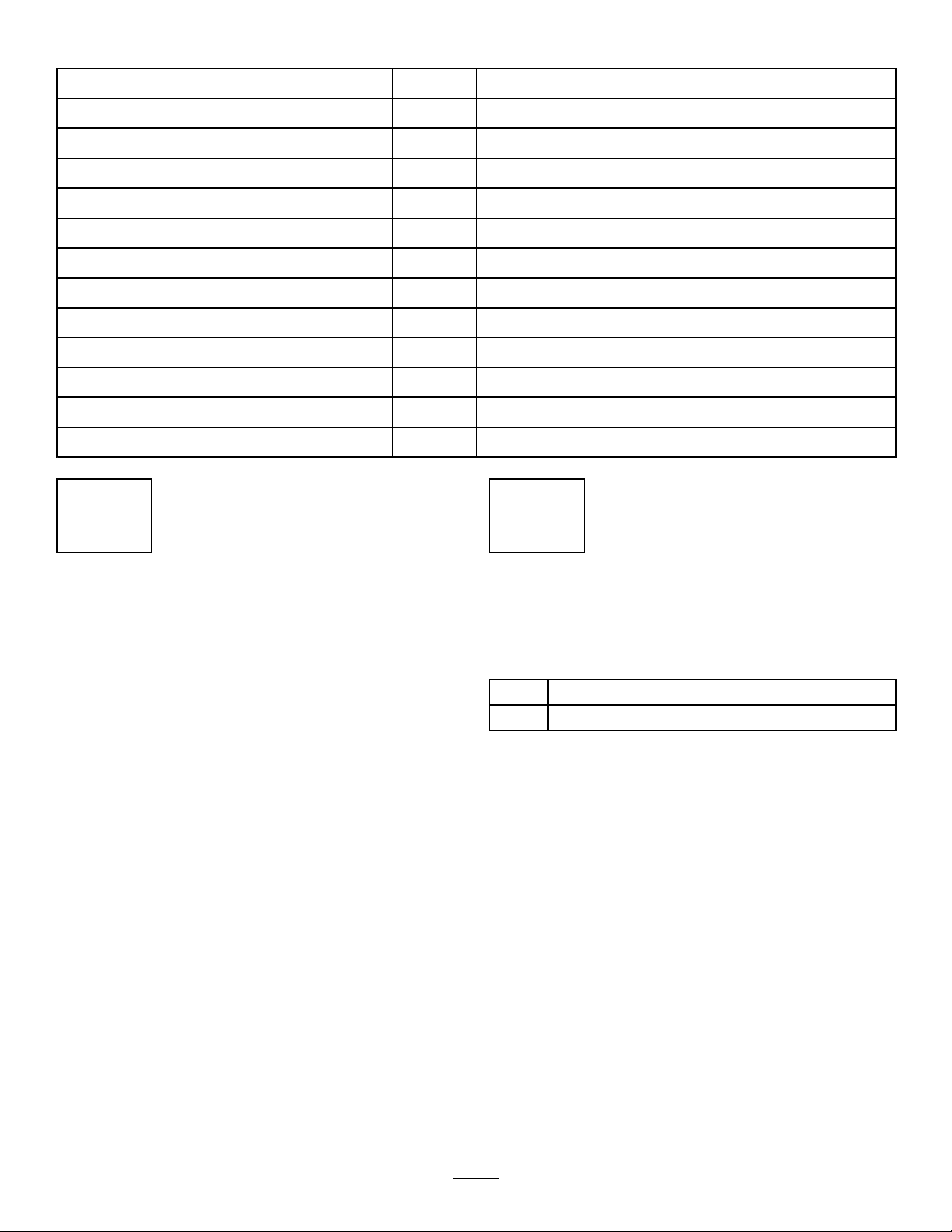
4.Securethelowerlinkarmstotheaeratormounting
pinswithlynchpins(
1.Aeratormountingpin3.Lynchpin
2.Lowerlink
Figure3).
Figure3
3
Connectingthe
HydraulicTopLink
(ModelsSR48,SR54,SR70,
SR72andSR75)
Partsneededforthisprocedure:
1Hydraulictoplink
1
Hydraulichose,3–1/2feet
1
Hydraulichose,2–1/2feet
2Extensionbracket
1Rotationalbracket
2Hosequickcouplings
Procedure
Note:Makesurethesuppliedcouplingsarecorrectfor
thetractor.Ifnot,itwillbenecessarytocontactthe
tractormanufacturertoobtainthecorrectcouplings.
SR48,SR70,SR70-S,SR72andSR75Aerators
only
5.Securethelowerlinkarmstotheaeratormounting
bracketswithhitchpinsandlynchpins(
Figure4
1.Hitchpin3.Lowerlink
2.Aeratormountingbracket4.Lynchpin
Figure4).
Thetractormustbeequippedwithadoubleactingspool
valvewithanoperatorcontrolleverandtwo1/2inch
(12.7mm)quick-releasecouplingsattherearofthe
tractor.Twoquickcouplingshavebeenprovidedtot
tothehydraulictoplinkhoses(1/2–14NPTFhoseend
threadsize).
Thissectionwillbeusedtoinstallthehosesand
determinetheneedfortheextensionorrotationblocks.
Thisinformationwillhelptodeterminethedepthrange
oftheaerator.
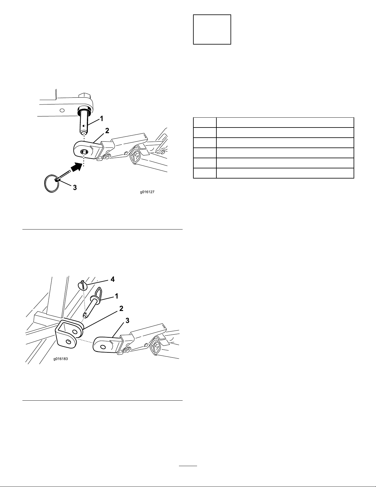
1.Securetheconnectinglinkendofthehydraulictop
linktothetractorwiththepinssuppliedwiththe
tractor(
therodendistowardtheaerator.Thecylinderports
shouldbepositionedtowardthetractor'sauxiliary
powerhydraulics.
Note:Ifthehydrauliccylindermustbepositioned
withtheportsfacingupward,usetherotationalblock
insteadofthestandardmountingblocktoreposition
thecylinder(
maybeusedinsteadoftherotationalblock(ttings
arenotsupplied).
Figure5).Positionthehydraulictoplinkso
Figure5).A90degreehydraulictting
Installtherotationalblockasfollows:
A.Removethecotterpinandpinsecuring
thestandardconnectinglinktothecylinder
10
Page 11
(Figure5).Removetheconnectinglinkfromthe
cylinder.
B.Installtherotationalblocktothecylinderwith
thepinspreviouslyremoved(
Figure5
Figure5).
Important:Whensecuringtherodendof
thehydrauliclink,makesuretousethemost
forwardmountingholesinthemountingbracket
sothereisenoughclearanceforthebarrelofthe
cylinderwhenretracted.
1.Aeratorhitchpin7.Tractorlinkpin
2.Hydraulictoplink
3.Rotationalblock
4.Connectinglink10.3–1/2foothydraulichose
5.3inchextensionblock11.Hosequickcouplings
6.5inchextensionblock12.Tractorhydraulicports
8.Clevis&lynchpin
9.2–1/2foothydraulichose
2.Connectthe3–1/2footlonghydraulichosetothe
hydraulictoplinkportwhichisclosesttotheaerator
Figure5.ApplyTeontapeorpipethreadsealantto
thehosethreadstopreventanyleaks.
3.Connectthe2–1/2footlonghydraulichosetothe
hydraulictoplinkportwhichisclosesttothetractor
Figure5).ApplyTeontapeorpipethreadsealant
(
tothehosethreadstopreventanyleaks.
4.Installquickcouplingstothehydraulichoses
(1/2–14NPTFhoseendthreadsize).ApplyTeon
tapeorpipethreadsealanttothehosethreadsto
preventanyleaks.
5.Connectthetwohydraulichosequickcouplingsto
theportsprovidedonthetractor.
6.Startthetractorengineandoperatethetractorspool
valvetochecktheextendandretractmotionofthe
hydraulictoplink.
Note:Reversethehoseconnections,atthetractor,
iftheydonoagreewiththetractorcontroloperation.
Figure6
SR54andSR70mountingshown
1.Rodendofcylinder
2.Lynchpin
SR48andSR72mountingshown
1.Lynchpin3.Linkpin
2.Aeratorbracket
3.Linkpin
4.Aeratorbracket(forward
Figure7
4.Rodendofcylinder
holes)
7.Securetherodendofhydraulictoplinktothemost
forwardholepossibleintheaeratorbracketwithlink
pinandlynchpin(
Figure6,Figure7orFigure8).
11
Page 12

Figure8
SR75mountingshown
1.Linkpin
2.Aeratorbracket4.Lynchpin
Ifthehydrauliccylinderdoesnotreachtheaerator
mountingbracket,useanextensionblockinsteadof
thestandardmountingblocktoconnectthecylinder
tothetractor(Figure5).
3.Rodendofcylinder
4
Connectingthe
TractorUpperLink
(ModelsSR54–SandSR70–S)
Partsneededforthisprocedure:
1
Springloadedtoplink
3Linkpin
3Lynchpin
Procedure
1.Mountthespringloadedtoplinktotheaerator
bracketwithtwolinkpinsandlynchpins(
2.Loosenthelocknutonthetractorupperlink.Adjust
theupperlinklengthuntilitalignswiththeclevison
thespringloadedtoplinkoftheaerator(Figure9).
Figure9)
Note:Ifanextensionblockisinstalledandthe
cylinderneedstoberetractedtobeinstalled,the
aeratortineheadswillgetclosertotheground.
Installtheextensionblocksasfollows:
A.Removethecotterpinandpinsecuring
thestandardconnectinglinktothecylinder
Figure5).Removetheconnectinglinkfromthe
(
cylinder.
B.Installtherequiredlengthextensionblockto
thecylinderwiththepinspreviouslyremoved
Figure5).
(
Figure9
1.Springloadedtoplink
2.Upperlink5.Locknut
3.Linkpin
3.Connectthetractorupperlinktotheclevisonthe
springloadedtoplinkandsecurewithalinkpinand
lynchpin(
4.Greasethethreadedsteelupperlinktubes.
5.Measurethelengthofthespringinthetoplink.
Figure9).
4.Lynchpin
6.Rotatetheupperlinkuntilthespringiscompressed
byabout1/2inch(
7.Tightenthelocknuttosecuretheupperlinkinto
position.
12
Figure9).
Page 13

5
VerifyingtheHydraulicTop
LinkSetUp
NoPartsRequired
Procedure
•Extendingthehydrauliccylinderwillincreasethe
tinedepth.
•Fullyextendthehydrauliccylindertodetermine
thelocationofthetineheadsandtoverifyifthey
contacttheground.
CAUTION
Ifthetineheadscontacttheground,turf
damagemayoccur.
Note:Onundulatingturf,theoperatorcanadjust
thecylindertomaintaintinedepth(crestingahill)
butitwillbenecessarytohavethetineheadsset
about2inchesbelowground.
•Ifthetineheadscontacttheground,adjustthe
locationofthecylinderendstomovethetopofthe
aeratorclosertothetractor.
•Ifthetineheadsdonotcontacttheground,
extensionbrackets(includedwithaerator)canbe
installedtothetoplinktomovethetineheadscloser
totheground.
Important:WhenconnectingthePTO,besure
thattheaeratorisnotbeingliftedhigherthanis
necessary.Liftingthemachinetoohighwillcause
thePTOshaftknucklestobreak(
leavethePTOturningwhentheaeratorislifted.
ThePTOcanbeoperateduptoanangleof25º,but
canneverexceeda35ºanglewhentheaeratoris
atitshighestpositionorsevereshaftdamagemay
occur.
Figure10).Never
Figure10
1.Breakagewilloccurhere
6
CheckingthePTOAngle
NoPartsRequired
Procedure
Important:Makesurethetinesareremovedbefore
performingthisoperation.
Withtheaeratorpositionedonthegroundandlowered
tothedeepestlocation,checktheanglebetweenthe
PTOandtheaerator.
Lifttheaeratorandfullyretractthehydraulictoplink
cylinder.Usinganangleindictor,checktheangle
betweenthePTOandtheaerator.Ifthisangleisgreater
than35degrees,makeadjustmentstothetractorso
thattheaeratorcannotbeliftedpast35degrees.This
canbeaccomplishedbyusingthetractorliftstop(if
soequipped)ormovingthelowerlinkstoahigher
mountinghole(ifsoequipped).
13
Page 14

7
FittingthePTOshaft
Partsneededforthisprocedure:
1
PTOshaft
Procedure
1.Movethetractorandaeratortoalevelsurface.
2.Raisetheaeratorcompletelyandfullyretractthe
hydraulictoplinkcylinderorupperlink(
Figure11
3.Measurethedistancefromthelockinggrooveonthe
endofthetractorPTOshafttothelockinggroove
ontheaeratorgearboxPTOshaft(Figure12).
Recordthisdistance.Example:26.5inches(67cm).
Figure11).
Figure13
5.Measurethedistancefromthelockinggrooveonthe
endofthetractorPTOshafttothelockinggroove
ontheaeratorgearboxPTOshaft(
Recordthisdistance.Example:27.5inches(70cm).
Figure14
1.Measurehere2.Lockinggroove
6.OnthePTOshaft,measurethedistancefromthe
centeroflockingpinballononeendtothecenterof
thelockingpinontheotherend(Figure15).Record
thisdistance.Example:32inches(81cm).
Figure14).
Figure12
1.Measurehere2.Lockinggroove
4.Lowertheaeratortothegroundandfullyextendthe
hydraulictoplinkcylinderorupperlink(Figure13).
Figure15
1.Measurehere
7.Usingthesmallerofthetwomeasurementsin
Figure14andFigure12,subtractthatdistancefrom
thedistanceinFigure15.Example32(81cm)inches
minus26.5inches(67cm)equals5.5inches(14cm).
8.Theexamplemeasurementsshowthattheshaftis
5.5inchestoolong.Addanextra1/2inch(1.2cm)
tobesurethatthePTOshaftwillnotbottomout
whentheaeratorisliftedtoitshighestposition.
Example:5.50inches(14cm)plus1/2inch(1.2cm)
equals6.00inches(15cm).
14
Page 15

9.SlidethePTOshafttubestogetheruntiltheyare
fullycollapsed.V erifythattheinsidetubedoesnot
protrudeintothecrossandbearingsectionofthe
outertube(
havetobecutofftheinsidetube,tocorrectthe
problem.Proceedtonextstep.
10.Measurethedistancetheinsidetubeprotrudesinto
thecrossandbearingsectionoftheoutertube
Figure16).Addthisdistancetothedimension
(
attainedinstep8.
Figure16).Ifthishappens,morewill
telescopingtubesmusthaveasuitableoverlapto
maintainthetubesalignmentandallowthemtoslide
freely.
Figure16
1.Cutoff
11.SeparatethetwohalvesofthePTOshaft(Figure17,
illustration1).
12.Measurethedistancefromtheendofeachtubeto
itssafetyshield(Figure17,illustration1).Record
thedistances.
13.Usingthedimensionsdeterminedinstep8,locate,
markandcutofftheshieldandtubefromeachPTO
half(Figure17,illustrations2&3).
Note:Morewillhavetobecutofftheinsidetubeif
itwasprotrudingintothecrossandbearingsection
oftheoutertube.
14.Usingthedimensionsdeterminedinstep11,locate,
markandcutoffjustthesafetyshieldstoexposethe
tubesFigure17,illustrations4&5.
15.Carefullydeburrtheendsofthetubeswithaleand
removeallthelingsfromthetubes.
16.Greasetheinsidetube.
Note:Telescopingtubesmustalwaysoverlapby
1/2oftheirlengthinnormaloperationandatleast
1/3oftheirlengthinallworkingconditions.During
transport,whenthedrivelineisnotrotating,the
2.Insidetube
Figure17
1.Measurehere
8
InstallingthePTOShield
Partsneededforthisprocedure:
1
PTOShield
Procedure
1.Removethe4bolts,lockwashersandatwashers
securedtotherearoftheaeratorgearbox(
Figure18).
15
Page 16

Figure18
1.PTOshield
2.Flatwasher5.Accesspanel
3.Lockwasher
4.Bolt
2.MountthePTOshieldtotheaeratorgearboxwith
thefastenerspreviouslyremoved(Figure18).When
mountingthePTOshield,makesuretheaccess
panel(
Figure18)ispositionedtothetoporside
dependingontheaeratorframeconguration.
9
ConnectingthePTOShaft
Partsneededforthisprocedure:
1
Pin(suppliedwithPTOshaft)
1
Nut(suppliedwithPTOshaft)
Figure19
1.Gearboxinputshaft
2.PTOshaftcoupler
3.Pin
4.Nut
Note:MakesuretocloseandlatchthePTOshield
accesspanelifopened.
Note:Makesurethepinisfullyinsertedintothe
yokeofthePTO.
3.ConnectthePTOshafttothetractorPTOshaft
(Figure20).
Procedure
Note:Theaccesspanel(Figure18)canbeopened
toeasetheremovalandinstallationofthePTOshaft
mountingfasteners.
1.RemovethepinandnutfromthePTOshaft
Figure19).
(
2.ConnecttheclutchendofthePTOshafttothe
aeratorgearboxinputshaftwithpinandnut
previouslyremoved(
beinsertedoneway .
Figure19).Thepincanonly
Figure20
1.Tractoroutputshaft3.PTOshaft
2.PTOshaftcoupler
4.SlidethePTOshaftforwardasfarasthetractor
allows.
5.PullbackonthelockingcollartosecurethePTO
shaftinplace.SlidethePTOshaftbackandforthto
makesureitisproperlylocked.
6.ConnecttheshieldsafetychainstothePTOshield
andthetractorbracket(
Figure21).Makesurethe
chainsremainslackwhentheaeratorisraisedor
lowered.
16
Page 17

Figure21
1.Safetychains
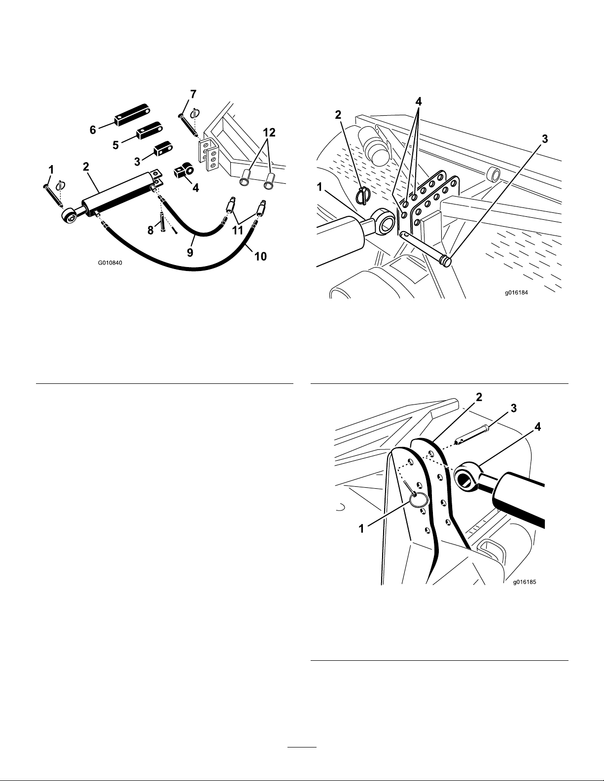
Note:Toavoidexcesslift,connecttheliftarmsof
thetractorintothetopholesoftheliftbracket,if
soequipped(
thePTOshaftis35º.
1.Topholes
Figure22).Themaximumangleon
Figure22
Figure23
1.Breakagewilloccurhere
10
AdjustingtheSwayLinks
NoPartsRequired
Procedure
Theaeratorisdesignedtobecenteredwiththetractor
PTOshaftcenterline.Adjusttheswaylinksasrequired.
ThePTOshaftshouldbeasstraightaspossibletothe
tractorPTOshaft.
Important:WhenconnectingthePTO,be
surethattheaeratorisnotbeingliftedhigher
thanisnecessary.Liftingthemachinetoohigh
willcausethePTOshaftknucklestobreak
Figure23).NeverleavethePTOturningwhen
(
theaeratorislifted.ThePTOcanbeoperated
uptoanangleof25º,butcanneverexceeda35º
anglewhentheaeratorisatitshighestposition.
7.VerifythatthePTOshielddoesnotinterferewith
theclutch.
Adjusttheswaylinksonthelowerliftarmstominimize
side-to-sideswaytoamaximumof1inch(25mm)on
eachside(
1.Swaylink
Figure24).
Figure24
17
Page 18

Adjustthelowerlinksinboarduntiltheycontactthe
aeratormountingplates.Thiswillreducethestress
onthepins.Ifthetractorhasswaychainsinsteadof
swaylinks,itisrecommendedthatwashersbeinstalled
betweenthelowerlinkarmandlynchpintoreducethe
overhungloadontheliftpins.
12
InstallingtheTines
Note:RefertothetractorOperator'sManualfor
additionalinstallationandadjustmentprocedures.
11
LevelingtheAerator
Side-to-Side
Partsneededforthisprocedure:
1
Level(notsupplied)
Procedure
1.Parkthetractorandaeratoronalevel,rmsurface.
2.Placealevelontopoftheaeratorframetocheckfor
levelside-to-side(
Figure25).
Partsneededforthisprocedure:
Tines
A/R
Procedure
Awideselectionoftinesareavailablefortheaerator.
Choosethetinetype,sizeandspacingsrequiredforthe
job.RefertothePartsCatalogforthelistofaccessories.
1.Makecertaintheaeratorisfullysupportedonthe
standsorsupportblocks.
2.Turnoffthetractorengineandremovethekey.
3.Loosentheclampingboltsandremovethepreviously
usedtines(Figure26).
Figure25
1.Level
3.Turntheadjustablelinkbody(ifprovided)toraise
orlowerthelinkarmuntiltheaeratorisleveled
side-to-side.
Note:RefertotractorOperator'sManualfor
additionaladjustmentprocedures.
Figure26
1.Tine
4.Slidethenewtinesintotheholessizedtotthetines
selected.Neverusesmalldiametertinesinthelarge
diameterholes-thetinesshouldtcloselyinthe
hole.Besuretoslidethetineupintotheheaduntil
itbottomsout.
Note:Hollowcoringtinesshouldbepositioned
withtheejectionslottotherearwhilethesolidtines
shouldhavethetinetipanglefacingthemachine
Figure26).
(
5.Tightentheclampingboltsrmlytosecurethetines.
6.Setthetineangleforthenewtines.Referto
AdjustingtheTineAngleintheOperationsection.
7.Beforeaeratingformalturfforthersttimeafter
installingtines,testtheaeratoronalessimportant
areasothatyoucantryalternativetractorgearsand
netunetheadjustmenttoachievetheholespacing
andturfappearancedesired.
2.Clampingbolt
18
Page 19

13
14
SettingtheTineDepth
(ModelsSR54–SandSR70–S)
NoPartsRequired
Procedure
Thetinedepthcanbechangedbyraisingorloweringthe
rearroller.Therollerheightisadjustedbymovingthe
rolleradjustingboltstothedesiredposition.
Note:TheaeratorisshippedinPositionA.
InstallingtheRearGuard
Partsneededforthisprocedure:
1Rearguard
4
Screw,3/8x3–1/4inch
12Flatwasher ,.438x1.00inch
4Locknut
2Endcap
Procedure
1.Inserttheendcapsintotheendsoftherearguard
tubes(
Figure28).
Figure27
•PositionA-Maximumdepth
•PositionB-Depthisdecreased1–1/2inchesfrom
PositionA
•PositionC-Depthisdecreased3inchesfrom
PositionA
Figure28
1.Rearguard3.Uppermountinghole
2.Endcap4.Lowermountinghole
2.Aligntheholesintherearguardmountingtubes
withtheholesintheaeratorsideplates(Figure28).
Note:OnSR54–SandSR70–Smodels,mountthe
endsofthetubestothelowersideplatemounting
holesiftheaeratortinedepthissetinPositionA
(
Figure29).Usetheuppermountingholesfordepth
settingPositionsBorC.
19
Page 20

Figure29
3.Securetheguardmountingtubestothesideplates
with(4)screws,atwashersandnuts(
Note:Usetheremainingwashers,asrequired,toll
anygapbetweenthetubesandtheaeratorsideplates.
Figure28).
15
Figure30
1.Retainingring3.Latchplate
2.Mountinghole4.Tapbolt
2.Securethelatchplatetothesideplatewithatapbolt
andaretainingring(Figure30).
InstallingtheLatchLock
Partsneededforthisprocedure:
2Lockplate
2Tapbolt
2Retainingring
Procedure
1.Positionthelatchplateoverthehoodlatchwhile
aligningthemountingholewiththeholeintheside
Figure30).
plate(
3.Repeattheprocedureontheotherhoodlatch.
16
RemovingtheStorageStands
(ModelsSR54andSR70)
NoPartsRequired
Procedure
1.Raisetheaeratorroller(s)3-6inchesoffground.
Placesupportblocksundertheroller(s).
2.Removethebolts,lockwashersandnutssecuringthe
storagestandstoeachendoftheaerator(
Figure31).
20
Page 21

Figure31
1.Bolts3.Nut
2.Lockwasher
3.Removethestoragestands.
4.Usethestoragestandswhenevertheaeratoris
removedfromthetractor.
4.Storagestand
3.Removethestoragestands.
4.Usethestoragestandswhenevertheaeratoris
removedfromthetractor.
Note:Whenreinstallingthestoragestands,make
suretheyaremountedtotheinsideoftheroller
platessothelowerframetubewillrestonthetopof
thestands.
Note:TheSR75shippingstandisalsothestorage
standandtheSR54-SandtheSR70-Sdonothave
shippingstands.
17
RemovingtheStorageStands
(ModelsSR48andSR72)
NoPartsRequired
Procedure
1.Raisetheaeratorroller(s)3-6inchesoffground.
Placesupportblocksundertheroller(s).
2.Removetheboltsandnutssecuringthestorage
standstoeachendoftheaerator(
Figure32).
Figure32
1.Bolts3.Nut
2.Lockwasher
4.Storagestand
21
Page 22

ProductOverview
Specications
Note:Specicationsanddesignaresubjecttochangewithoutnotice.
withPTO&TopLink
WorkingWidth48”
WorkingDepth
(Adjustable)
HoleSpacing
Productivity25,000
Recommended
TractorSize
Recommended
LiftCapacity
Recommended
CounterWeight
Recommended
PTOSpeed
ActualWorking
Speed@400
PTORPM
(Varieswithhole
LiftSystemStd.3–pointStd.3–pointStd.3–pointStd.3–pointStd.3–pointStd.3–pointStd.3–point
ProCore
SR48
Weight
spacing)
1,530lbs.
(694kg)
(1.22m)
1”-14”
(25–300mm)
3”-6”
(75–150mm)
sq.ft./hr.
(2,325
sq.m/hr.)
25HP16–18HP18HP25–35HP25–35HP45HP55+HP
1,800lbs.
(817kg)
300lbs.
(135kg)
400–500rpm400–500rpm400–500rpm400–500rpm400–500rpm400–460rpm400–500rpm
.8–1.3mph1.5–2.5mph1.5–2.5mph1.5–2.5mph1.5–2.5mph.8–1.5mph.8–1.5mph
ProCore
SR54
1165lbs.
(528kg)
(1.37m)
1”-10”
(25–250mm
2.5”-4”
(64–102mm)
36,000
sq.ft./hr.
(3,345
sq.m/hr.)
1,200lbs.
(544kg)
150lbs.
(70kg)
ProCore
SR54–S
1,242lbs.
(563kg)
54”
54”
(1.37m)
1”-10”
(25–250mm
2.5”-4”
(64–102mm)
36,000
sq.ft./hr.
(3,345
sq.m/hr.)
1,500lbs.
(680kg)
150lbs.
(70kg)
ProCore
SR70
1,373lbs.
(623kg)
(1.85m)
1”-10”
(25–250mm
2.5”-4”
(64–102mm)
48,000
sq.ft./hr.
(4,460
sq.m/hr.)
1,700lbs.
(771kg)
250lbs.
(115kg)
ProCore
SR70–S
1,498lbs.
(679kg)
73”
73”
(1.85m)
1”-10”
(25–250mm
2.5”-4”
(64–102mm)
48,000
sq.ft./hr.
(4,460
sq.m/hr.)
1,800lbs.
(817kg)
250lbs.
(115kg)
ProCore
SR72
2,091lbs.
(948kg)
(1.83m)
1”-16”
(25–400mm)
3”-6”
(75–150mm)
38,000
sq.ft./hr.
(3,530
sq.m/hr.)
2,800lbs.
(1,270kg)
300–500lbs.
(135–225kg)
ProCore
SR75
3,100lbs.
(1,406kg)
72”
78”
(1.98m)
1”-16”
(25–400mm
3”-6”
(75–150mm)
48,000
sq.ft./hr.
(4,460
sq.m/hr.)
4,000lbs.
(1,815kg)
700–900
(315–410kg)
Attachments/Accessories
AselectionofToroapprovedattachmentsand
accessoriesareavailableforusewiththemachineto
enhanceandexpanditscapabilities.Contactyour
AuthorizedServiceDealerorDistributororgoto
www.Toro.comforalistofallapprovedattachments
andaccessories.
22
Page 23

Operation
Note:Determinetheleftandrightsidesofthe
machinefromthenormaloperatingposition.
ontherevcounters.SincetheengineandPTOrpmsare
directlyproportional,youcandeterminetheenginerpm
requiredfora400rpmPTObycalculatingasfollows:
(Enginerpmat540PTOspeed)x(400÷540)=requiredengine
rpm
TractorControls
Itisnecessarytofamiliarizeyourselfwiththeoperation
ofthefollowingtractorcontrolsbeforeyouareableto
operatetheaerator:
•PTOEngagement
•Engine/PTORpm
•3PointHitch(Raise/Lower)
•AuxiliaryValveOperation
•Clutch
•Throttle
•GearSelection
•Parkingbrake
Note:RefertotractorOperator'sManualfor
operatinginstructions.
PrinciplesofOperation
Thetractor'sthreepointhitchlinkage/hydraulictop
linkliftstheaeratorfortransportandlowersitfor
operation.
Thetractor'spowertakeoff(PTO)poweristransmitted
viashafts,gearboxandO-ringdrivechainstoa
crankshaftwhichdrivesthetineholdingarmsintothe
turfsurface.
AsthetractortravelsforwardwiththePTOengaged
andthemachinelowered,aseriesofholesarecreated
intheturfsurface.
Thedepthofthetine'spenetrationisdeterminedby
extendingthehydraulictoplinkorsettingthexedtop
linktothedesiredposition.
Note:Donotattempttoadjustaxedtoplinkwhile
themachineisrunning.
Thedistancebetweentheholescreatedisdetermined
bythetractor'sgearratio(orhydrostatictractionpedal
position)andthenumberoftinesineachtinehead.
Simplychangingenginerpmdoesnotchangehole
spacing.
Forexample,iftheenginerpmwere2700foraPTO
speedof540rpm,youwouldget:
2700x(400÷540)=2000rpm
Inthisexample,runningyourtractorat2000rpmnow
providesyouwitha400rpmPTOspeed.
Ifyourtractorindicatessomeotherenginerpmat540
PTOrpm,substitutethatnumberforthe2700thatwas
usedabove.
Note:TherecommendedPTOspeedfor10inchtines
andshorteris460rpmand425rpmfortineslonger
than10inches.
TrainingPeriod
Beforeusingtheaerator,ndaclearareaandpractice
usingthemachine.Operatethetractoratrecommended
gearsettingsandPTOdrivespeedsandbecome
thoroughlyfamiliarwithmachinehandling.Practice
stoppingandstarting,raisingandloweringtheaerator,
disengagingthePTOdriveandaligningthemachine
withpreviouspasses.Apracticesessionassures
condenceintheperformanceoftheaeratorandhelps
ensureuseofproperoperatingtechniqueswherever
themachineisoperated.
Iftherearesprinklerheads,electricalorcommunication
linesorotherobstructionsintheareatobeaerated,
marktheseitemstoensuretheyarenotdamagedduring
operation.
CAUTION
Toavoidpersonalinjury,neverleavethetractorseat
withoutrstdisengagingthePTOdrive,setting
theparkingbrakeandstoppingtheengine.Never
performaeratorrepairswithoutrstlowering
theaeratorontothestoragestandorappropriate
blockingorjacks.Besureallsafetydevicesare
securedinproperplacebeforeresumingoperation.
BeforeAerating
TractorPTOSpeed
TheaeratorisdesignedtooperatewithaPTOspeed
ofupto500rpmdependingonthesize/weightofthe
tines.Mosttractorsindicatea540PTOrpmposition
Inspecttheareaofoperationforhazardsthatcould
damagethemachineandremovethem,ifpossible,
orplanhowtoavoidthem.Carryreplacementtines,
springwires,springsandtoolsincasetinesaredamaged
duetocontactwithforeignmaterials.
23
Page 24

Important:Neveroperatetheaeratorinreverseor
whenitisintheraisedposition.
AeratingProcedures
Important:Iftheaeratorhasbeenstoredforan
extendedperiod,checktomakesurethePTOslip
isoperational.RefertoAdjustingthePTOClutch
intheMaintenanceSection.
1.Lowertheaeratorsothatthetinesarenearlytothe
groundatthelowestpartoftheirstroke.
2.Atalowtractorenginerpm,engagethepowertake
off(PTO)clutchtostarttheaeratorworking.
3.Selectagearthatgivesaforwardspeedof
approximately.8-2.5M.P .H.(1to4km/hr.)at
theratedPTOspeedof400–500rpm(refertothe
tractorOperator'sManual).
4.Astheclutchisreleasedandthetractormoves
forward,lowertheaeratorfullyontotheroller(s)
andincreaseenginespeedtogiveamaximumof
400–500rpm(460onmodelSR72)atthePTO .
Important:NeveroperatethetractorPTO
inexcessof500rpmordamagetotheaerator
couldoccur.
Important:Makesurethattherollerison
thegroundatalltimeswhentheaeratoris
operating.
5.Notetheholepattern.Ifyourequiregreaterhole
spacing,increaseforwardthespeedofthetractorby
shiftingupagearorwithahydrostaticdrivetractor,
actuatethehydrostatleverorpedaltogivefaster
speed.Forcloserholespacing,decreasetractor
forwardspeed.Changingenginespeed,whilein
thesamegear,willnotchangetheholepattern.
Important:Lookbehindfrequentlyto
ensurethemachineisoperatingproperlyand
alignmentismaintainedwithpreviouspasses.
6.Usethefronttractorwheelasaguidetomaintain
equallateralholespacingwiththepreviouspass.
7.Attheendoftheaerationpass,raisetheaeratorand
quicklydisengagethePTO.
8.Ifyoubackintoatightarea(likeateebox),
disengagethePTOandraisetheaeratortoits
highestposition.Neverattempttoaerateinreverse.
frombeingpickedupbymowersorotherturf
maintenanceequipmentandthrown.
10.Replacebrokentines,inspectandcorrectdamageto
thosestillusable.Repairanyothermachinedamage
beforecontinuingoperation.
OperatingTips
1.EngagePTOatlowenginespeed.Increaseengine
speedtoachievethedesiredPTOspeedof400–500
rpm(maximum)andtheloweraerator.Operateat
anenginerpmthattheaeratorrunsmostsmoothly .
Note:Changingtheengine/PTOrpmina
particulartractorgear(orxedhydrostaticpedal
positionontractorswithhydrostatictransmission)
willnotchangeholespacing.
2.Makeverygradualturnswhenaerating.Nevermake
sharpturnswithPTOdriveengaged.Planyour
aerationpathbeforeloweringtheaerator.Making
sharpturnswhileaeratingwilldamagetheaerator
andthetines.
3.Iftractor“bogs”downwhenoperatingonhard
groundorgoinguphill,raiseaeratorslightlyuntil
speedisregained,thenloweraeratoragain.
4.Bestresultsareachievedwhenthetineentryisona
slightinclinetowardtherearofthemachine.Use
cautionwhenextendingthehydraulictoplinkto
keepfromhammeringtheturfwiththetineheads.
Insomecases,youmaynotachievethebestresults
fromusingthepre-setholesinthecamberbrackets.
Especiallywherethegrassrootsareshortorweak.
Youmaywanttoexperimentusinganothercamber
settingthatwillsetthetinesonmoreofanincline
tokeepfrompullingsoiloutofthehole.
5.Donotaerateifthegroundistoohardordry.Best
resultsareobtainedafterarainorwhenturfhas
beenwateredthepreviousday .
Note:Iftherollerridesupoffthegroundwhile
aerating,thegroundistoohardtoachievethe
desireddepth,reducetheaerationdepthuntilthe
rollercontactsthegroundduringoperation.
6.Raiseaeratorpenetration,ifgroundishardpacked.
Cleanupcoresandre-aerateatdeeperpenetration,
preferablyafterwatering.
9.Alwayscleartheareaofalldamagedmachineparts,
suchasbrokentines,etc.,topreventanything
24
Page 25

CAUTION
Toavoidpersonalinjury,neverleavethetractor
seatwithoutrstdisengagingthePTOdrive,
settingtheparkingbrakeandstoppingthe
engine.Neverperformaeratoradjustmentsor
repairswithoutrstloweringtheaeratoronto
thesafetystand.Besureallsafetydevices
aresecuredinproperplacebeforeresuming
operation.
7.Lookbehindfrequentlytoensurethemachineis
operatingproperlyandalignmentismaintainedwith
previouspasses.Alossofonelineofholesindicates
abentorlosttine.Inspectaftereachpass.
8.Alwayscleartheareaofalldamagedmachine
parts,suchasbrokentines,etc.,topreventthem
frombeingpickedupbymowersorotherturf
maintenanceequipmentandthrown.
toohardtopenetrate.Whenthetinescontactthis
subsoiltheaeratormayliftandcausethetopofthe
holestobecomeelongated.Reducetheaerationdepth
sufcientlytoavoidpenetrationintothehardsubsoil.
Longer/LargerTines
Usinglonger/largertinescanleavethefrontorrearof
theholetuftedorslightlydeformed.Holequalityfor
thiscongurationgenerallyimprovesifthecoringhead
speedisreduced10-15%fromfulloperatingspeed.For
PTOpoweredaeratorsreducetheenginespeeduntil
thePTOspeedisaround400–420rpm.Theforward
spacingisnoteffectedbyreducingtheenginespeed.
Thepushedholecanalsobeaffectedbythepositionof
thecamberbracket.RefertoAdjustingtheTineAngle.
MultiRowAdapterHeads
9.Replacebrokentines,inspectandcorrectdamageto
thosestillusable.Repairanyothermachinedamage
beforecommencingoperation.
SubsoilCultivation
Subsoilcultivation,fracturingor“heave”iscreatedbya
spadingmotionofthetineinthesoilastheaeratorand
tractormoveforward.Qualityofnishontheplaying
surfaceafteraeratingwilldependonvariousfactors
includingturfcondition,rootgrowthandmoisture
content.
HardGround
Ifthegroundistoormtoobtainthedesiredaeration
depth,thecoringheadcangetintoa“bouncing”
rhythm.Thisisduetothehardpanthetinesare
attemptingtopenetrate.Thisconditioncanbe
correctedbyattemptingoneormoreofthefollowing:
•Bestresultsareobtainedafterarainorwhenturf
hasbeenwateredthepreviousday.
•Reducethenumberoftinesperstomper
arm.Attempttomaintainasymmetricaltine
congurationtoevenlyloadthestomperarms.
•Reduceaeratorpenetration(depthsetting)ifground
ishardpacked.Cleanupcores,waterturf,and
aerateagainatadeeperpenetration.
Aerationofsoiltypesbuiltontopofhardsubsoils
(i.e.sand/soilcapplacedoverrockyground)cancause
undesiredholequality.Thisiscausedwhentheaeration
depthisgreaterthanthesoilcapandthesubsoilis
Whenusingmultirowadapterheads,reducetheengine
speeduntilthePTOspeedisaround400–420rpm.
Theforwardspacingisnoteffectedbyreducingthe
enginespeed.
RootZoneLifting
Usingmulti-tineheadsinconjunctionwithlargercoring
tinesorlargediametersolidtinescaninducesignicant
stressontherootzoneoftheturf.Thisstresscan
fracturetherootzoneandcausealiftingactiontothe
turf.Ifthisdamageoccurstryoneormoreofthe
following:
•Reducetinedensity(removesomeofthetines)
•Decreasecoringdepth(suggestedin1/2inch
increments)
•Increaseforwardholespacing(changetractor
transmissionuponegear)
•Decreasethetinediameter(solidorcoring)
UsingtheHoodPropRods
ModelSR75only
1.Releasethelatchoneachsideoftheaeratorhood.
2.Raisethehood.
3.Oneachsideofthehood,pivottheproproddown
frommagneticstoragebracketandinsertitintothe
proprodcatch(Figure33).
25
Page 26

g017489
1
2
3
Figure34
Figure33
1.Proprodcatch3.Magneticstoragebracket
2.Proprod
4.Whenloweringthehood,returntheproprodsto
themagneticstoragebrackets.
AdjustingtheTineAngle
ModelSR72
Setthecamberbracket(Figure34)tothecorrect
positionbasedonthelengthoftinestobeused.The
headstopissettooneofvepredeterminedpositions
bychoosingtheholethroughwhichtheadjustmentrod
isbolted.Theseholesarepresetsonly;forinstance,by
usinga10inchtineinthe12inchpositionyoumay
achieveasmoothernish;dependingontheapplication.
1.DisengagethePTOandengagetheparkingbrake.
2.Stoptheengineandremovethekeyfromignition
switch.
3.Releasethespringtensiontothetinehead
Figure34).
(
4.Removethenutandboltintheadjustmentholesin
thecamberbracket(Figure34).
1.Camberbracket
2.16inchtine6.14inchtine
3.12inchtine7.Tineheadpivotbolt
4.7inchtine
5.10inchtine
8.Spring
5.Rotatethecamberbracketuntilitisalignedwiththe
desiredholeinthearmandinstalltheboltandnut.
Note:Makesuretheboltgoesthroughthe
chamberbracketandplate.
6.Reconnectthespringtensiontothetinehead.
ModelsSR54,SR54–S,SR70and
SR70–S
Setthetineangleaccordingtothetinelengthbyusing
oneofthetwoadjustmentholesinthelinkagearm.
Theseholesarepresetsonly .Whenusing7inch(17.77
cm)to10inch(25.4cm)tines,theheadbumpershould
bepositionedclosesttotherearofthetinehead.The
otherposition(theholefarthestfromthehead)maybe
neededduetovariancesofsoilconditions.
1.DisengagethePTOandengagetheparkingbrake.
2.Stoptheengineandremovethekeyfromignition
switch.
3.Releasethespringtensiontothetinehead
Figure35).
(
26
Page 27

4.Removethenutandboltintheadjustmentholesin
thecamberbracket(Figure36).
5.Rotatethecamberbracketuntilitisalignedwith
thedesiredholeinthearmandinstalltheboltand
Figure36).
nut(
Note:Makesuretheboltgoesthroughthe
chamberbracketandplate.
6.Reconnectthespringtensiontothetinehead.
Figure35
1.Spring3.Springpinandclip
2.Bumperbolt
4.Removethebumperboltandbumperfromthe
linkagearmandreinsertthemintotheother
adjustmenthole(Figure35).
5.Reconnectthespringtensiontothetinehead.
ModelSR75
Setthecamberbracket(Figure36)tothecorrect
positionbasedonthelengthoftinestobeused.The
headstopissettooneofvepredeterminedpositions
bychoosingtheholethroughwhichtheadjustmentrod
isbolted.Theseholesarepresetsonly;forinstance,by
usinga10inchtineinthe12inchpositionyoumay
achieveasmoothernish;dependingontheapplication.
1.DisengagethePTOandengagetheparkingbrake.
2.Stoptheengineandremovethekeyfromignition
switch.
3.Releasethespringtensiontothetinehead
(Figure36).
AdjustingtheTineDepth
(ModelsSR54–SandSR70–S)
Thetinedepthcanbechangedbyraisingorlowering
therearroller.Therollerheightisadjustedbymoving
therolleradjustingboltstothedesiredposition.
Note:TheaeratorisshippedinPositionA.
Figure37
•PositionA-Maximumdepth
•PositionB-Depthisdecreased1–1/2inchesfrom
PositionA
Figure36
1.10inchtine
2.7inchtine6.Tineheadpivotbolt
3.12inchtine7.14inchtine
4.16inchtine
5.Camberbracket
8.Spring
•PositionC-Depthisdecreased3inchesfrom
PositionA
TransportOperation
Tobegintransportoperation,raisetheaeratorand
disengagethePTO.Toavoidlossofcontrol,traverse
steepinclinesslowly,approachroughareasatreduced
speedandcrosssevereundulationscarefully.
Important:Donotexceedtransportspeedsof15
m.p.h.(24km/hr.).
27
Page 28

InspectionandCleanupafter
Use
Afterdailyuse,thoroughlywashthemachinewitha
gardenhosewithoutanozzlesocontaminationandseal
andbearingdamageduetoexcessivewaterpressurewill
beavoided.Abrushmaybeusedtoremovecaked-on
material.Usemilddetergenttocleanthecovers.After
cleaning,greasealldrivelinesandrollerbearings,
inspectformachinedamage,oilleakage,component
andtinewear.DonotoiltheO-ringdrivechain.
Remove,cleanandoilthetines.Sprayalightoilmiston
coringheadbearings(crank&damperlinks).
Cleanandcoatthespringswithadrylubricantlike
graphiteorsilicone.
28
Page 29

Maintenance
RecommendedMaintenanceSchedule(s)
MaintenanceService
Interval
Aftertherst50hours
Beforeeachuseordaily
Every50hours
Every500hours
Beforestorage
Yearly
MaintenanceProcedure
•ChangetheGearboxOil
•Inspectthechaintension
•Checkthesprings
•Cleanandlubricatespringsandtinemountingscrews
•InspectthePTOforsignsofwear.
•GreasethebearingsandPTOshaft
•ChecktheGearboxOil
•Inspectthechaintension
•Inspectbearings
•ChangetheGearboxOil
•Inspectbearingsandreplaceasneeded
•Oiltineholderfasteners
•Performall50hourmaintenanceprocedures
•Chippedsurfaces-Paint
•LoosenthePTOclutchbolts
•Removeandcleantines
•Removealldebris
•AdjustthePTOclutchBeforeandafterstorage
LiftingtheMachine
CAUTION
Whenchangingattachmentsorperformingother
service,usecorrectblocks,hoistsorjacks.Make
suremachineisparkedonasolidlevelsurface
suchasaconcreteoor.Priortoraisingmachine,
removeanyattachmentsthatmayinterferewith
thesafeandproperraisingofthemachine.Always
chockorblocktowvehiclewheels.Usestorage
standsorblockstosupporttheraisedmachine.If
themachineisnotproperlysupported,themachine
maymoveorfall,whichmayresultinpersonal
injury.
Note:Ahoistcanbeusedtolifttheaerator.Use
thecoringheadeyeletasahoistattachmentpoint
(Figure38).Makesurethehoisthasenoughliftcapacity.
Refertothespecicationchartforaeratorweights.
Figure38
1.Coringheadeyelet
29
Page 30

GreasingtheBearings
ServiceInterval:Every50hours
Themainworkingbearingsoftheaeratoraresealedand
requirenomaintenanceorlubrication.Thisdrastically
reducesthemaintenancerequiredandeliminatestherisk
ofgreaseoroilbeingdroppedontotheturf.
Therearegreasettingsthatmustbelubricatedwith
anSAEmultipurpose,high-temperaturegreasewith
highpressure(EP)performanceorSAEmultipurpose
lithiumbasegrease.
Thelubricationpointsare:
PTOShaft(3)(
Rollerbearings(Qty .2or4,dependingonmodel)
(Figure40)
Figure39)
Figure39
Thesealedbearingsrequirenolubricationorshortterm
maintenance.Thisminimizesroutineservicerequired
andreducesthepotentialofturfdamageduetogrease
contamination.Thesesealedbearingpackageswill
providegoodperformanceandlifeundernormaluse,
butperiodicinspectionsofbearingconditionandseal
integrityshouldbeconductedtoavoiddowntime.These
bearingsshouldbeinspectedseasonallyandreplacedif
damagedorworn.Bearingsshouldoperatesmoothly
withnodetrimentalcharacteristicssuchashighheat,
noise,loosenessorrustweeping.
Duetotheoperatingconditionsthesebearing/seal
packagesaresubjectto(i.e.sand,turfchemicals,water,
impacts,etc.)theyareconsiderednormalwearitems.
Bearingsthatfailduetootherthandefectsinmaterialsor
workmanshiparetypicallynotcoveredunderwarranty.
Note:Bearinglifecanbenegativelyaffectedby
improperwashdownprocedures.Donotuse
high-pressureorhighvolumespraydirectlyatthe
bearings.
Itiscommonfornewbearingstopurgesomegreaseout
thesealsonanewunit.Thispurgedgreasewillturn
blackincolorduetocollectionofdebrisandnotdueto
excessiveheat.Itisgoodpracticetowipethisexcess
greasefromthesealsaftertheinitial8hours.Theremay
alwaysappeartobeawetareaaroundtheseallip.This
isgenerallynotdetrimentaltobearinglife,butkeeps
thesealliplubricated.
Inspectthecoringheadbearingsevery500operating
hoursandreplaceasneeded.
Figure40
O-ringchain—Donotlubricatethechain.
Important:Bearingsrarelyfailfromdefectsin
materialsorworkmanship.Themostcommon
reasonforfailureismoistureandcontamination
workingitswaypasttheprotectiveseals.Bearings
thataregreasedwillrelyuponregularmaintenance
topurgeharmfuldebrisfromthebearingarea.
Sealedbearingsrelyonaninitialllofspecialgrease
andarobustintegralsealtokeepcontaminantsand
moistureoutoftherollingelements.
CheckingtheGearboxOil
ServiceInterval:Every50hours
Thegearboxislledwith80W–90gearoilorequivalent.
Allowthegearboxtocoolbeforecheckingtheoillevel.
1.Cleandebrisfromllplugandcheckplugtoavoid
contamination.
2.Removethecheckplugfromthegearbox(
Note:Ifthegearboxhastwocheckplugs,usethe
bottomone.
Figure41).
30
Page 31

Model
SR482quarts(1.9liters)
SR542quarts(1.9liters)
SR54–S2quarts(1.9liters)
SR702quarts(1.9liters)
SR70–S2quarts(1.9liters)
SR724quarts(3.8liters)
SR754quarts(3.8liters)
GearCaseCapacity
6.Installthevent/llplug.
7.Checktheoillevelandreplenishasrequired.
Inspecting/AdjustingtheDrive
Chain
ServiceInterval:Beforeeachuseordaily
Figure41
1.Vent/Fillplug
2.Checkplug
3.Drainplug
3.Makesureoilisuptothebottomofthecheckplug
holeingearbox(Figure41).
4.Ifoillevelislow ,removevent/llplugfromtopof
gearboxandreplenishoilasrequired.
5.Installplugs.
ChangingtheGearboxOil
ServiceInterval:Aftertherst50hours
Every500hours
Thegearboxislledwith80W–90gearoilorequivalent.
1.Cleandebrisfromvent/llpluganddrainplugto
avoidcontamination(
2.Removethevent/llplugtorelieveairdraw .
Figure41).
Every50hours
Checkthedrivechainfordamageandcorrect
adjustment.Thechainshouldhaveapproximately1/2
inch(12.7mm)ofoveralldeection(1/4inch[6mm]in
eachdirection).
Chaintensioncanbeadjustedbyslightlylooseningthe
mainjamnutandtighteningthejamrodtodesired
position(
Figure42orFigure43).Donotadjustthe
chaintensionwhenthechainishotorwarm.
3.Positionadrainpanunderthedrainplugandremove
theplug.
Note:Thehighviscosityofcooloilwillextendthe
draintime.(approximately30minutes)
4.Aftertheoiliscompletelydrained,reinstallthedrain
plug.
5.Fillthegearboxwithhighquality80W -90gearlube.
Usethefollowingcharttodeterminethegearbox
oilcapacity .
Figure42
ModelsSR54,SR54–S,SR70,&SR72
1.Drivechain3.Jamrod
2.Jamnut
31
Page 32

Note:Donotallowtheclutchtoslipforan
extendedamountoftime.
3.Iftheclutchcontinuestoslipafterturningbackthe
nuts,tighteneachnutanaddition1/4turnuntilthe
slippingceases.Donotovertightenthenutsasshaft
damagemayoccur.
FastenerTorque
Specications
Figure43
ModelSR72
1.Drivechain3.Jamrod
2.Jamnut
Important:Donotovertightenchains;excess
tighteningofchainscancausegearbox/sprocket
damage.
AdjustingthePTOClutch
ServiceInterval:YearlyBeforeandafterstorage
WARNING
Frictionclutchesmaybecomehotduringuse.
not touch.
aroundtheclutchfreeofammablematerialand
avoidprolongedslippingoftheclutch.
Toavoidtheriskofre,keepthearea
ModelsSR54,
SR54–S,
SR70&
SR70–S
CrankShaft
Nut
CrankPinNut950ft-lbs.950ft-lbs.1100ft-lbs.
HingeBolt
950ft-lbs.1200ft-lbs.1100ft-lbs.
265ft-lbs.300ft-lbs.800ft-lbs.
SR48&SR72SR75
Do
1.Attheendoftheseason,backoffeachoftheclutch
nuts2turns(Figure44).
Figure44
1.Clutchnut2.Clutch
2.Atthestartofthenewseason,startthePTOand
allowtheclutchtoslipforafewsecondsbefore
stoppingthePTO.Turnbackthenutsanadditional
2turns.
1.Crankshaftnut
2.Crankpinnut
Figure45
3.Hingebolts
32
Page 33

CheckingtheSprings
ServiceInterval:Beforeeachuseordaily
Checkthespringsforcrossedorbrokenwires
(Figure46).Crossedorbrokenspringwireswillcause
anerraticholepatternintheturf.
Figure46
1.Correctspringwires2.Crossedspringwires
Note:Replacementwiresareincludedwiththeaerator.
Thewiresareconsideredaconsumableitem.
hosesandtheconnectinglinkfromthetractor.Cap
thehydraulichoses.Storethesecomponentswith
theaerator.
10.DisconnectthesafetyshieldchainsfromPTOshaft.
11.Pullbackonthelockcollartodisconnectthepower
shaftfromthetractorPTOshaft.
12.SlidethePTOshaftbackandremovefromtractor.
13.ConnectthePTOsafetychaintotheaeratorto
preventthePTOshaftfromcontactingtheground.
14.Removethepinssecuringthelowerlinkarmstothe
aeratorbrackets.Retainpinswithaerator.
AdjustingtheHoleSpacing
Theforwardholespacingisdeterminedbythetractor's
gearratio(orthehydrostatictractionpedal).Changing
theengineRPMdoesnotchangetheforwardhole
spacing.
Thelateralholespacingisdeterminedbythenumber
oftinesinthetineheads.
RemovingtheAeratorfrom
theTractor
1.Stoptheaeratoronalevelsurface,notonaslope.
2.DisengagethePTOandengagetheparkingbrake.
3.Raisetheaeratorroller(s)3-6inchesoffground.
Placesupportblocksundertheroller(s).
4.Stoptheengineandremovethekeyfromignition
switch.
5.BeforeleavingtheOperator'sseatontractor,wait
forengineandallmovingpartstostop.
6.Removethetines.
7.Installthestoragestand.
8.Slowlyloweraeratoruntilstoragestandscontact
ground.
9.Removethepinsecuringthetoplinktotheaerator
bracket.Retainpinwithaerator.Also,onmodels
withahydraulictoplink,disconnectthehydraulic
33
Page 34

TroubleShooting
Problem
Springsarebreakingornotpullingbackthe
headtonormalposition.
Holesareelongatedorpicking.
Tinesarehittingthegroundwithanerratic
pattern.
PTOclutchslipsexcessively.
Turfispullingupwithcoringtines.Shallow-rootedturfmayrequiresolidtinesthersttime.
Thesoilistoohardforfullpenetration.
Coringtinesarebreaking.Youaretryingtogettoomuchdepthforthesoilcondition.Seeaboveandaerateto
Tineswillnotstayinthehead.
Tinespullthesoilupwhenthemachineis
raised.
Themachinewillnotturn.
Thetractorhasdifcultyliftingtheaerator.Movetractorliftarms3”(76.19mm)to4”(101.6mm)closertotheaerator.Make
Thehydraulictoplinkcylinderisspongy.(It
“gives”andmovesinandoutashortspan
whenforceisapplied.
Machineisnoisyorknocking.
Thehydraulictoplinkcylindercannotbefully
retracted(PTOshaftjams).
Thetractorisdifculttosteerwhenintransport.•Addweighttothefrontofthetractor.
Camberbracketdamage
SlowthePTOspeedofthetractor.Thelongerandheavierthetines,thegreaterthe
centrifugalforceonthehead.Checkforcrossedorbrokenspringwires.
Adjusttheangleofthetineorchangethetractorgroundspeed.Makesurethatthe
aeratorcanbeloweredatleast2inchesbelowatgroundleveltoallowforundulation.
•Checkforcrossedorbrokenspringwires.
•SlowthePTOspeedofthetractor.
Adjusttinestoashallowerdepth.Reviewclutchadjustmentprocedure.Replace
PTOclutches.
Aerateatadepththatthemachinecanachieve,waterovernight,andthenincrease
thedepth.Repeatifnecessaryuntilsoilcanbeaeratedatdesireddepth.
ashallowerdepth.
Tightenthetineholderbolts;donotusejamnutsorimpactwrench.Iftheboltwillnot
holdthetine,replaceit.
RaisethemachinepartofthewayoutofthesoilbeforedisengagingthePTO.
MakesurethePTO,driveshaftanddrivechainsareworkingproperly .
surethetractorhasthecapacitytolifttheaerator.
Airisinthecylinderorlinesandmustbebledout.
•Crankpinnuthasvibratedloose.
•Chainsaretooloose.
•Boltsonthebottomoftheframeattherearofthemainarmhavevibratedloose.
•Checkoillevelingearbox.
ThePTOshaftistoolongforyourtractorandshouldbecuttothecorrectlength.
•Checktirepressureandadjustasrequired.
•Donotstoretheaerator,ontheground,withtinesinstalled.
•Donotrunthecoringhead,foranextendedtimeathighRPM,whenthetines
areoutoftheground.
Solution
34
Page 35

Storage
Attheendofanaeratingseasonorwhentheaeratorwill
notbeusedforalongperiod,itisgoodpracticetocarry
outthefollowingpreventativemaintenance.
1.Cleanoffanydirtorgreasethatmayhave
accumulatedontheaeratororanyofthemoving
parts.
2.Removeandcleanouttines.Coattinesandtine
fastenerswithoiltopreventrustingduringstorage.
3.Openthehoodandcleanouttheinsideofthe
machine.
4.Lubricateallgreasettingsandtinefastenerscrew
threads.
5.Storethemachineontheprovidedstoragestandson
ahard,drysurface.
6.LoosenthePTOclutchboltstwoturns.
7.ConnectthePTOsafetychaintotheaeratorinstored
positiontopreventdamageorremovethePTOand
storeunderthehoodtominimizecorrosion.
8.Painttherollerandtouch-upanyotherscratcheson
thepaintedsurfaces.
9.Replaceanymissingordamageddecals.
10.Storetheaeratorinsideadrysecurebuilding.Inside
storagewillreducemaintenance,givealonger
workinglifeandincreasetheresidualvalueofthe
machine.Ifinsidestorageisnotavailable,coverwith
aheavysheetortarpaulinandsecuretightly.
35
Page 36

ToroCommercialAeratorProductsWarranty
Atwo-YearLimitedWarranty
ConditionsandProductsCovered
TheToroCompanyanditsafliate,ToroWarrantyCompany,pursuant
toanagreementbetweenthem,jointlywarrantyourT oroHydroject
orProCoreAerator(“Product”)tobefreefromdefectsinmaterialsor
workmanshipfortwoyearsor500operationalhours*,whicheveroccurs
rst.Thiswarrantyisapplicabletoallproductswiththeexceptionof
Aerators(refertoseparatewarrantystatementsfortheseproducts).
Whereawarrantableconditionexists,wewillrepairtheProductatnocost
toyouincludingdiagnostics,labor,parts,andtransportation.Thiswarranty
beginsonthedatetheProductisdeliveredtotheoriginalretailpurchaser.
*Productequippedwithanhourmeter.
InstructionsforObtainingWarrantyService
YouareresponsiblefornotifyingtheCommercialProductsDistributoror
AuthorizedCommercialProductsDealerfromwhomyoupurchasedthe
Productassoonasyoubelieveawarrantableconditionexists.Ifyouneed
helplocatingaCommercialProductsDistributororAuthorizedDealer,or
ifyouhavequestionsregardingyourwarrantyrightsorresponsibilities,
youmaycontactusat:
CommercialProductsServiceDepartment
ToroWarrantyCompany
811 1LyndaleAvenueSouth
Bloomington,MN55420-1196
952–888–8801or800–952–2740
E-mail:commercial.warranty@toro.com
OwnerResponsibilities
AstheProductowner,youareresponsibleforrequiredmaintenance
andadjustmentsstatedinyourOperator’sManual.Failuretoperform
requiredmaintenanceandadjustmentscanbegroundsfordisallowinga
warrantyclaim.
ItemsandConditionsNotCovered
Notallproductfailuresormalfunctionsthatoccurduringthewarranty
periodaredefectsinmaterialsorworkmanship.Thiswarrantydoesnot
coverthefollowing:
•Productfailureswhichresultfromtheuseofnon-Tororeplacement
parts,orfrominstallationanduseofadd-on,ormodiednon-T oro
brandedaccessoriesandproducts.Aseparatewarrantymaybe
providedbythemanufactureroftheseitems.
•Productfailureswhichresultfromfailuretoperformrecommended
maintenanceand/oradjustments.Failuretoproperlymaintain
yourToroproductpertherecommendedmaintenancelistedinthe
Operator’sManualcanresultinclaimsforwarrantybeingdenied.
•ProductfailureswhichresultfromoperatingtheProductinan
abusive,negligentorrecklessmanner.
•Partssubjecttoconsumptionthroughuseunlessfoundtobe
defective.Examplesofpartswhichareconsumed,orusedup,during
normalProductoperationinclude,butarenotlimitedto,brakes
padsandlinings,clutchlinings,blades,reels,bedknives,tines,
sparkplugs,castorwheels,tires,lters,belts,andcertainsprayer
componentssuchasdiaphragms,nozzles,andcheckvalves,etc.
•Failurescausedbyoutsideinuence.Itemsconsideredtobeoutside
inuenceinclude,butarenotlimitedto,weather,storagepractices,
contamination,useofunapprovedcoolants,lubricants,additives,
fertilizers,water,orchemicals,etc.
•Normalnoise,vibration,wearandtear ,anddeterioration.
•Normal“wearandtear”includes,butisnotlimitedto,damageto
seatsduetowearorabrasion,wornpaintedsurfaces,scratched
decalsorwindows,etc.
Parts
Partsscheduledforreplacementasrequiredmaintenancearewarranted
fortheperiodoftimeuptothescheduledreplacementtimeforthatpart.
Partsreplacedunderthiswarrantyarecoveredforthedurationofthe
originalproductwarrantyandbecomethepropertyofToro.T orowill
makethenaldecisionwhethertorepairanyexistingpartorassemblyor
replaceit.T oromayuseremanufacturedpartsforwarrantyrepairs.
MaintenanceisatOwner’sExpense
Enginetune-up,lubricationcleaningandpolishing,replacementof
ItemsandConditionsNotCovered,lters,coolant,andcompleting
recommendedmaintenancearesomeofthenormalservicesToro
productsrequirethatareattheowner’sexpense.
GeneralConditions
RepairbyanAuthorizedT oroDistributororDealerisyoursoleremedy
underthiswarranty .
NeitherTheToroCompanynorToroWarrantyCompanyisliablefor
indirect,incidentalorconsequentialdamagesinconnectionwiththe
useoftheT oroProductscoveredbythiswarranty,includingany
costorexpenseofprovidingsubstituteequipmentorserviceduring
reasonableperiodsofmalfunctionornon-usependingcompletion
ofrepairsunderthiswarranty.ExceptfortheEmissionswarranty
referencedbelow,ifapplicable,thereisnootherexpresswarranty.
Allimpliedwarrantiesofmerchantabilityandtnessforusearelimitedto
thedurationofthisexpresswarranty.Somestatesdonotallowexclusions
ofincidentalorconsequentialdamages,orlimitationsonhowlongan
impliedwarrantylasts,sotheaboveexclusionsandlimitationsmaynot
applytoyou.
Thiswarrantygivesyouspeciclegalrights,andyoumayalsohaveother
rightswhichvaryfromstatetostate.
Noteregardingenginewarranty:
TheEmissionsControlSystemonyourProductmaybecoveredby
aseparatewarrantymeetingrequirementsestablishedbytheU.S.
EnvironmentalProtectionAgency(EP A)and/ortheCaliforniaAir
ResourcesBoard(CARB).Thehourlimitationssetforthabovedonot
applytotheEmissionsControlSystemWarranty.RefertotheEngine
EmissionControlWarrantyStatementprintedinyourOperator’sManual
orcontainedintheenginemanufacturer’sdocumentationfordetails
CountriesOtherthantheUnitedStatesorCanada
CustomerswhohavepurchasedT oroproductsexportedfromtheUnitedStatesorCanadashouldcontacttheirToroDistributor(Dealer)toobtain
guaranteepoliciesforyourcountry ,province,orstate.IfforanyreasonyouaredissatisedwithyourDistributor'sserviceorhavedifcultyobtaining
guaranteeinformation,contacttheToroimporter.Ifallotherremediesfail,youmaycontactusatT oroWarrantyCompany.
374-0270RevA
 Loading...