

Page 1
Form No. 10174SL Rev B
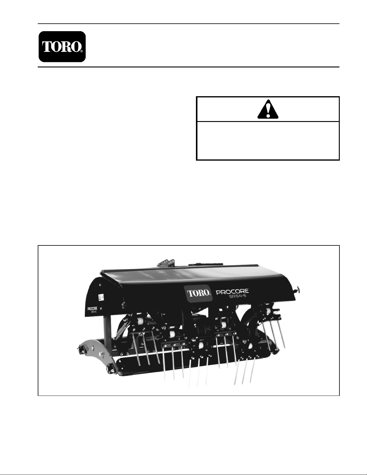
ProCore® SR Series
(Models SR48, SR54, SR54-S, SR70, SR70-S,
SR72 and SR75)
Original Instructions (EN)
Page 2

Revision History
Revision
Date
Description
--
2010
Initial Issue
A
02/2018
Added revision history.
B
07/2020
Updated Chassis chapter.
©
reproduced by a third party without the express written consent of The Toro Company (and/or the appropriate affiliated company).
THE TORO COMPANY 2020
This document and all information contained herein is the sole property of The Toro Company (and/or its affiliated companies). No
intellectual property rights are granted by the delivery of this document or the disclosure of its content. This document shall not be
Page 3

Reader Comments
The Toro Company Technical Assistance Center maintains a continuous effort to improve the quality
and usefulness of its publications. To do this effectively, we encourage user feedback.
Please comment on the completeness, accuracy, organization, usability, and readability of this manual
by an e-mail to servicemanuals@toro.com
or Mail to:
Technical Publication Manager, Commercial
The Toro Company
8111 Lyndale Avenue South
Bloomington, MN 55420-1196
Phone: +1 952-887-8495
Page 4

NOTES _
Page 5
Preface
The purpose of this publication is to provide the service
technician with information for troubleshooting, testing
and repair of major systems and components on the
ProCore SR series deep tine aerators: models SR48,
SR54, SR54--S, SR70, SR70--S, SR72 and SR75.
REFER TO THE OPERATOR’S MANUAL FOR OPERATING, MAINTENANCE AND ADJUSTMENT
INSTRUCTIONS. For reference, insert a copy of the
Operator’s Manuals and Parts Catalog for your machine
into Chapter 2 of this service manual. Additional copies
of the Operator’s Manuals and Parts Catalog are available on the internet at www.Toro.com.
The Toro Company reserves the right to change product
specifications or this publication without notice.
Part No. 10174SL (Rev. B)
Service Manual
ProCoreRSR Series
This safety symbol means DANGER, WARNING,
or CAUTION, PERSONAL SAFETY INSTRUCTION. When you see this symbol, carefully read
the instructions that follow. Failure to obey the
instructions may result in personal injury.
NOTE: A NOTE will give general information about the
correct operation, maintenance, service, testing or repair of the machine.
IMPORTANT: The IMPORTANT notice will give important instructions which must be followed to prevent damage to systems or components on the
machine.
E The Toro Company -- 2011, 2018, 2020
Page 6

This page is intentionally blank.
ProCore SR Series
Page 7

Table Of Contents
Chapter 1 -- Safety
Safety Instructions 1 -- 2..........................
Safety and Instruction Decals 1 -- 4................
Chapter 2 -- Product Records and Maintenance
Product Records 2 -- 1...........................
Maintenance 2 -- 1...............................
Equivalents and Conversions 2 -- 2................
Torque Specifications 2 -- 3.......................
Chapter 3 -- Chassis
General Information 3 -- 1........................
Service and Repairs 3 -- 2........................
Chapter 4 -- Coring Head (SR54 & SR70)
Specifications 4 -- 2..............................
General Information 4 -- 4........................
Special Tools 4 -- 7..............................
Service and Repairs 4 -- 8........................
Chapter 5 -- Coring Head (SR48 & SR72)
Specifications 5 -- 2..............................
General Information 5 -- 4........................
Special Tools 5 -- 6..............................
Service and Repairs 5 -- 8........................
SafetyProduct Records
and Maintenance
ChassisCoring Head
(SR54 & SR70)
Chapter 6 -- Coring Head (SR75)
Specifications 6 -- 2..............................
General Information 6 -- 4........................
Special Tools 6 -- 6..............................
Service and Repairs 6 -- 8........................
Chapter 7 -- Gearbox Service
General Information 7 -- 1........................
Service and Repairs 7 -- 2........................
Coring Head
(SR48 & SR72)
(SR75)
Coring Head
Service
Gearbox
ProCore SR Series
Page 8

This page is intentionally blank.
ProCore SR Series
Page 9

Chapter 1
Safety
Table of Contents
SAFETY INSTRUCTIONS 2......................
Before Operating 2............................
While Operating 3.............................
Maintenance and Service 3....................
SAFETY AND INSTRUCTION DECALS 4..........
Safety
ProCore SR Series Page 1 -- 1 Safety
Page 10
Safety Instructions
The ProCore SR series of deep tine aerators are designed and tested to offer safe service when operated
and maintained properly. Although hazard control and
accident prevention partially are dependent upon the
design and configuration of the machine, these factors
are also dependent upon the awareness, concern and
proper training of the personnel involved in the operation, transport, maintenance and storage of the machine. Improper use or maintenance of the machine can
result in injury or death. T o reduce the potential for injury
or death, comply with the following safety instructions.
Before Operating
WARNING
To reduce the potentialfor injury or death, comply with the following safety instructions.
1. Review and understand the contents of the Operator’s Manual before starting and operating the vehicle.
Become familiar with the controls and know how to stop
the vehicle and engine quickly. Additional copies of the
Operator’s Manual are available on the internet at
www.Toro.com.
2. Keep all shields, safety devices and decals in place.
If a shield, safety device or decal is defective, illegible
or damaged, repair or replace it before operating the
machine.
3. Make sure that the tractor is carefully selected to assure the best performance and safe operation of the
ProCore deep tine aerator.
4. Make sure that operator is familiar with safe tractor
operation.
5. Tighten any loose nuts, bolts or screws to ensure
machine is in safe operating condition.
6. Make sure that the ProCore deep tine aerator is
properly attached to tractor.
ProCore SR SeriesPage 1 -- 2Safety
Page 11

While Operating
IMPORTANT: T o prevent damage to your ProCore
aerator during operation:
• Never operate ProCore aerator without tine
heads installed.
• Do not operate the tractor in reverse when the
ProCore aerator is lowered.
• Make sure aerator roller is on ground before operating aerator. Never operate with the aerator in
the raised position.
• Never operate the tractor PTO in excess of 500
RPM.
1. Operator should be on the tractor when starting the
engine and when operating the aerator. Stay away from
the aerator coring head when it is engaged.
2. Before starting the engine on the tractor:
A. Apply the parking brake.
B. Make sure traction lever or transmission is in neutral and PTO is disengaged.
C. Refer to Tractor Operator’s Manual for safe starting procedures.
3. Do not run tractor engine in a confined area without
adequate ventilation. Exhaust fumes are hazardous
and could possibly be deadly.
4. If abnormal aerator vibration is detected, disengage
PTO and stop tractor immediately. Determine source of
vibration and correct problem(s) before resuming the
use of aerator.
5. While operating, the combination of the tractor and
the ProCore aerator may exceed noise levels of
85dB(A) at the operator position. Hearing protection is
recommended for prolonged exposure to reduce the potential of permanent hearing damage.
6. Before leaving the operator’s position of the tractor:
A. Disengage PTO power to aerator and lower aerator to the ground.
B. Apply parking brake on tractor. Stop engine and
remove key from ignition switch.
C. Wait for all moving parts to stop before leaving
the tractor.
Safety
Maintenance and Service
1. The Operator’s Manual provides information regarding the operation, general maintenance and maintenance intervals for your ProCore aerator. Refer to this
publication for additional information when servicing the
machine.
2. Before servicing or making adjustments to aerator,
disengage tractor PTO, position aerator on a level surface and lower aerator to the ground. Apply tractor parking brake, stop engine and remove key from the ignition
switch.
3. Make sure machine is in safe operating condition by
keeping all nuts, bolts and screws tight.
4. Use care when checking or servicing the coring
head: wear gloves and use caution.
5. Never step over the PTO shaft to reach other side of
aerator. Walk around the machine instead.
6. The friction clutch on the PTO driveshaft may become hot during use. Make sure that clutch has cooled
before performing any service on the driveshaft.
7. Before disconnecting aerator from tractor, install
storage stand to aerator frame and park aerator on a
hard, level surface.
8. After servicing the aerator, be sure that all guards
and covers are properly installed and secured.
9. At the time of manufacture, the machine conformed
to all applicable safety standards. To assure optimum
performance and continued safety certification of the
machine, use genuine Toro replacement parts and accessories. Replacement parts and accessories made
by other manufacturers may result in non-conformance
with the safety standards, and the warranty may be
voided.
10.If major repairs are ever needed or assistance is desired, contact an Authorized Toro Distributor.
ProCore SR Series Page 1 -- 3 Safety
Page 12

Safety and Instruction Decals
Numerous safety and instruction decals are affixed to
the ProCore SR series deep tine aerator. If any decal
becomes illegible or damaged, install a new decal. Part
numbers for replacement decals are listed in your Parts
Catalog. Order replacement decals from your Authorized Toro Distributor.
ProCore SR SeriesPage 1 -- 4Safety
Page 13

Product Records and Maintenance
Table of Contents
PRODUCT RECORDS 1.........................
MAINTENANCE 1...............................
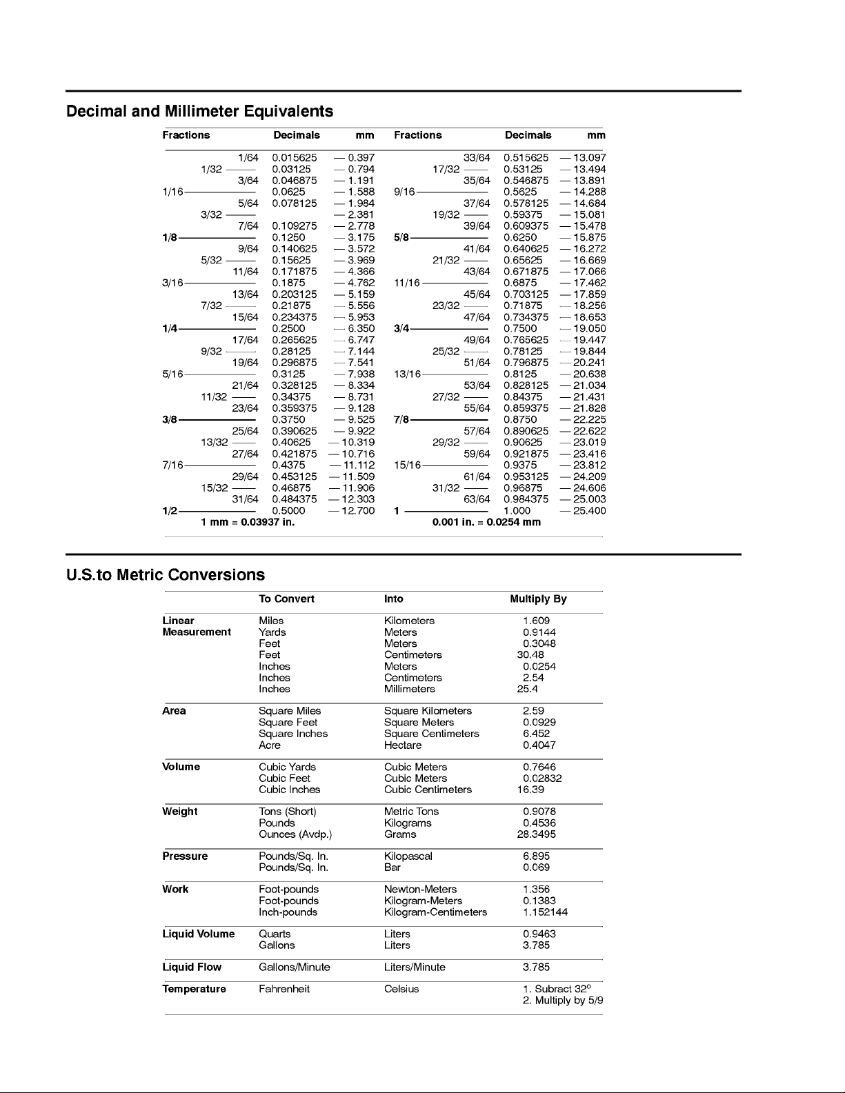
EQUIVALENTS AND CONVERSIONS 2...........
Decimal and Millimeter Equivalents 2............
U.S. to Metric Conversions 2...................
TORQUE SPECIFICATIONS 3....................
Fastener Identification 3.......................
Standard Torque for Dry, Zinc Plated and
Steel Fasteners (Inch Series) 4...............
Standard Torque for Dry, Zinc Plated and
Steel Fasteners (Metric Fasteners) 5...........
Other Torque Specifications 6..................
Conversion Factors 6..........................
Product Records
Chapter 2
Product Records
and Maintenance
Insert Operator’s Manual and Parts Catalog for your
ProCore SR Series deep tine aerator at the end of this
chapter. Additionally, if any optional equipment or accessories have been installed to your ProCore, insert
the Installation Instructions, Operator’s Manuals and
Parts Catalogs for those options at the end of this chapter.
Maintenance
Maintenance procedures and recommended service intervals for the ProCore SR Series deep tine aerator are
covered in the Operator’s Manual. Refer to that publication when performing regular equipment maintenance.
ProCore SR Series Page 2 -- 1 Product Records and Maintenance
Page 14
Equivalents and Conversions
0.09375
ProCore SR SeriesPage 2 -- 2Product Records and Maintenance
Page 15
Torque Specifications
Recommended fastener torque values are listed in the
following tables. For critical applications, as determined
by Toro, either the recommended torque or a torque that
is unique to the application is clearly identified and specified in this Service Manual.
These Torque Specifications for the installation and
tightening of fasteners shall apply to all fasteners which
do not have a specific requirement identified in this Service Manual. The following factors shall be considered
when applying torque: cleanliness of the fastener, use
of a thread sealant (e.g. Loctite), degree of lubrication
on the fastener, presence of a prevailing torque feature,
hardness of the surface underneath the fastener’s head
or similar condition which affects the installation.
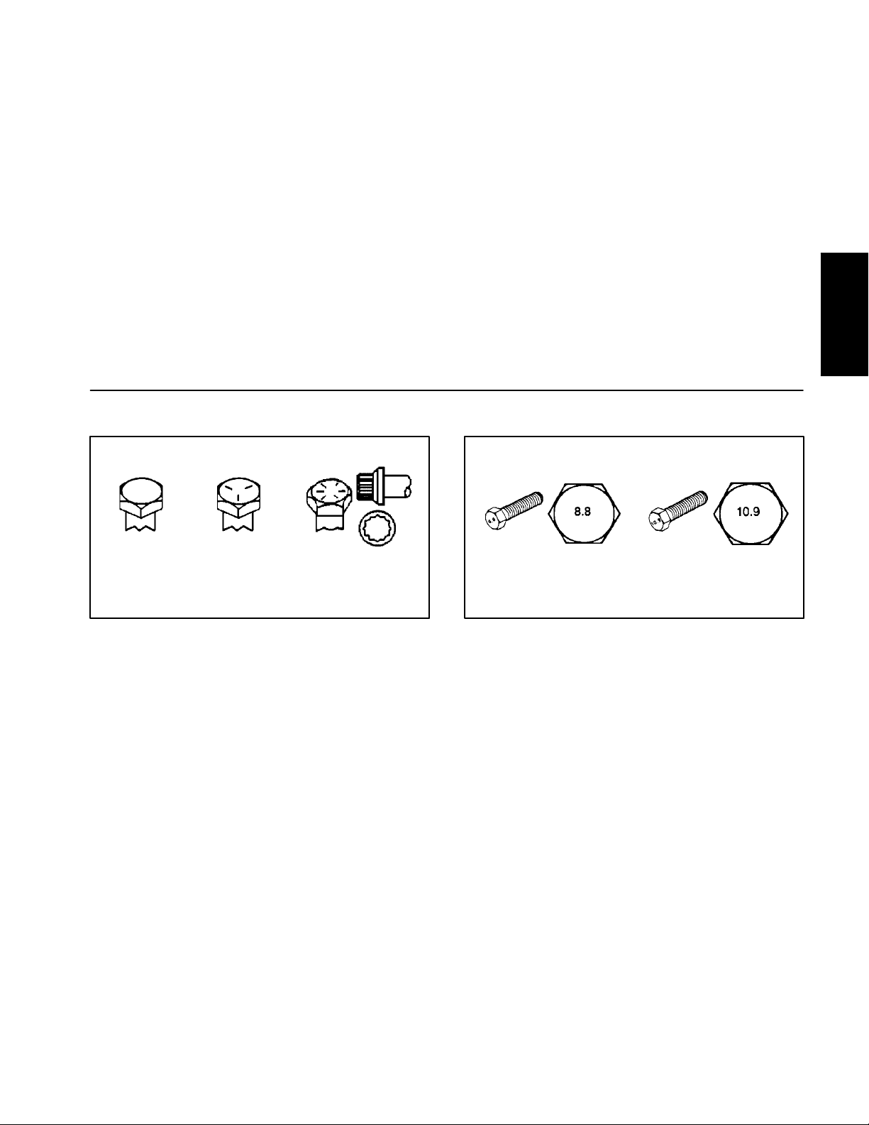
Fastener Identification
As noted in the following tables, torque values should be
reduced by 25% for lubricated fasteners to achieve
the similar stress as a dry fastener. Torque values may
also have to be reduced when the fastener is threaded
into aluminum or brass. The s pecific torque value
should be determined based on the aluminum or brass
material strength, fastener size, length of thread engagement, etc.
The standard method of verifying torque shall be performed by marking a line on the fastener (head or nut)
and mating part, then back off fastener 1/4 of a turn.
Measure the torque required to tighten the fastener until
the lines match up.
Product Records
and Maintenance
Grade 1 Grade 5 Grade 8
Inch Series Bolts and Screws
Figure 1
Class 8.8 Class 10.9
Metric Bolts and Screws
Figure 2
ProCore SR Series Page 2 -- 3 Product Records and Maintenance
Page 16

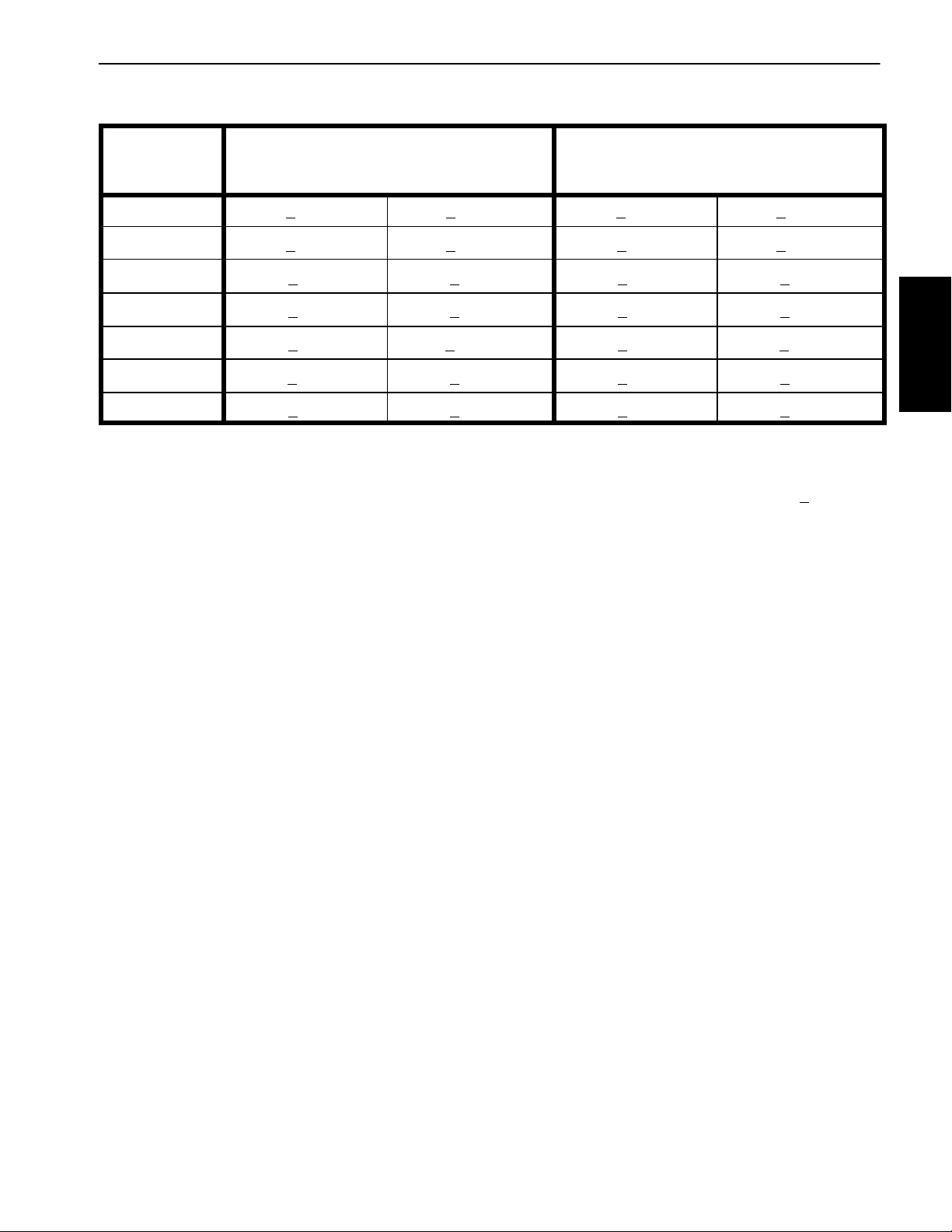
Standard Torque for Dry, Zinc Plated and Steel Fasteners (Inch Series)
Thread Size
# 6 -- 32 UNC
# 6 -- 40 UNF
# 8 -- 32 UNC
# 8 -- 36 UNF
#10--24UNC
#10--32UNF
1/4 -- 20 UNC 48 + 7 53 + 7 599 + 79 100 + 10 1125 + 100 140 + 15 1580 + 170
1/4 -- 28 UNF 53 + 7 65 + 10 734 + 11 3 11 5 + 10 1300 + 100 160 + 15 1800 + 170
5/16 -- 18 UNC 115 + 15 105 + 17 1186 + 169 200 + 25 2250 + 280 300 + 30 3390 + 340
5/16 -- 24 UNF 138 + 17 128 + 17 1446 + 192 225 + 25 2540 + 280 325 + 30 3670 + 340
3/8 -- 16 UNC 16 + 2 16 + 2 22 + 3 30 + 3 41 + 4 43 + 4 58 + 5
Grade 1, 5 &
8withThin
Height Nuts
in--lb in--lb N--cm in--lb N--cm in--lb N--cm
10 + 2 13 + 2 147 + 23
13 + 2 25 + 5 282 + 30
18 + 2 30 + 5 339 + 56
ft--lb ft--lb N--m ft--lb N--m ft--lb N--m
SAE Grade 1 Bolts, Screws, Studs &
Sems with Regular Height Nuts
(SAE J995 Grade 2 or Stronger Nuts)
SAE Grade 5 Bolts, Screws, Studs &
Sems with Regular Height Nuts
(SAE J995 Grade 2 or Stronger Nuts)
15 + 2 170 + 20 23 + 2 260 + 20
17 + 2 190 + 20 25 + 2 280 + 20
29 + 3 330 + 30 41 + 4 460 + 45
31 + 3 350 + 30 43 + 4 485 + 45
42 + 4 475 + 45 60 + 6 675 + 70
48 + 4 540 + 45 68 + 6 765 + 70
SAE Grade 8 Bolts, Screws, Studs &
Sems with Regular Height Nuts
(SAE J995 Grade 5 or Stronger Nuts)
3/8 -- 24 UNF 17 + 2 18 + 2 24 + 3 35 + 3 47 + 4 50 + 4 68 + 5
7/16 -- 14 UNC 27 + 3 27 + 3 37 + 4 50 + 5 68 + 7 70 + 7 95 + 9
7/16 -- 20 UNF 29 + 3 29 + 3 39 + 4 55 + 5 75 + 7 77 + 7 104 + 9
1/2 -- 13 UNC 30 + 3 48 + 7 65 + 9 75 + 8 102 + 11 105 + 10 142 + 14
1/2 -- 20 UNF 32 + 3 53 + 7 72 + 9 85 + 8 115 + 11 120 + 10 163 + 14
5/8 -- 11 UNC 65 + 10 88 + 12 119 + 16 150 + 15 203 + 20 210 + 20 285 + 27
5/8 -- 18 UNF 75 + 10 95 + 15 129 + 20 170 + 15 230 + 20 240 + 20 325 + 27
3/4 -- 10 UNC 93 + 12 140 + 20 190 + 27 265 + 25 359 + 34 375 + 35 508 + 47
3/4 -- 16 UNF 115 + 15 165 + 25 224 + 34 300 + 25 407 + 34 420 + 35 569 + 47
7/8 -- 9 UNC 140 + 20 225 + 25 305 + 34 430 + 45 583 + 61 600 + 60 813 + 81
7/8 -- 14 UNF 155 + 25 260 + 30 353 + 41 475 + 45 644 + 61 660 + 60 895 + 81
NOTE: Reduce torque values listed in the table above
by 25% for lubricated fasteners. Lubricated fasteners
are defined as threads coated with a lubricant such as
oil, graphite or thread sealant such as Loctite.
NOTE: The nominal torque values listed above for
Grade 5 and 8 fasteners are based on 75% of the minimum proof load specified in SAE J429. The tolerance is
approximately +
10% of the nominal torque value. Thin
height nuts include jam nuts.
NOTE: Torque values may have to be reduced when
installing fasteners into threaded aluminum or brass.
The specific torque value should be determined based
on the fastener size, the aluminum or base material
strength, length of thread engagement, etc.
ProCore SR SeriesPage 2 -- 4Product Records and Maintenance
Page 17
Standard Torque for Dry, Zinc Plated and Steel Fasteners (Metric Fasteners)
Class 8.8 Bolts, Screws and Studs with
Thread Size Regular Height Nuts
(Class 8 or Stronger Nuts)
M5 X 0.8 57 + 5in--lb 640 + 60 N--c m 78 + 7in--lb 885 + 80 N--cm
M6 X 1.0 96 + 9in--lb 1018 + 100 N--cm 133 + 13 in --lb 1500 + 150 N--cm
M8 X 1.25 19 + 2ft--lb 26 + 3N--m 27 + 2ft--lb 36 + 3N--m
M10 X 1.5 38 + 4ft--lb 52 + 5N--m 53 + 5ft--lb 72 + 7N--m
M12 X 1.75 66 + 7ft--lb 90 + 10 N--m 92 + 9ft--lb 125 + 12 N--m
M16 X 2.0 166 + 15 ft--lb 225 + 20 N--m 229 + 22 ft--lb 310 + 30 N--m
M20 X 2.5 325 + 33 ft--lb 440 + 45 N-- m 450 + 37 ft--lb 610 + 50 N--m
NOTE: Reduce torque values listed in the table above
by 25% for lubricated fasteners. Lubricated fasteners
are defined as threads coated with a lubricant such as
oil, graphite or thread sealant such as Loctite.
NOTE: Torque values may have to be reduced when
installing fasteners into threaded aluminum or brass.
The specific torque value should be determined based
on the fastener size, the aluminum or base material
strength, length of thread engagement, etc.
NOTE: The nominal torque values listed above are
based on 75% of the minimum proof load specified in
SAE J1199. The tolerance is approximately +
nominal torque value.
Class 10.9 Bolts, Screws and Studs with
Regular Height Nuts
(Class 10 or Stronger Nuts)
10% of the
Product Records
and Maintenance
ProCore SR Series Page 2 -- 5 Product Records and Maintenance
Page 18
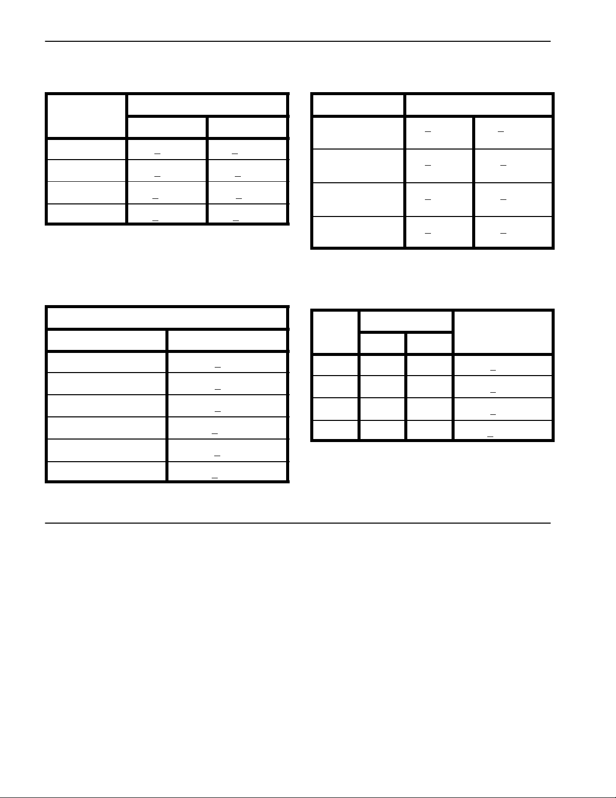
Other Torque Specifications
*
SAE Grade 8 Steel Set Screws
Recommended Torque
Thread Size
Square Head Hex Socket
1/4 -- 20 UNC 140 + 20 in--lb 73 + 12 in--lb
5/16 -- 18 UNC 215 + 35 in--lb 145 + 20 in--lb
3/8 -- 16 UNC 35 + 10 ft--lb 18 + 3ft--lb
1/2 -- 13 UNC 75 + 15 ft--lb 50 + 10 ft--lb
Thread Cutting Screws
(Zinc Plated Steel)
Type 1, Type 23 or Type F
Thread Size Baseline Torque*
No. 6 -- 32 UNC 20 + 5in--lb
Wheel Bolts and Lug Nuts
Thread Size
7/16 -- 20 UNF
Grade 5
1/2 -- 20 UNF
Grade 5
M12 X 1.25
Class 8.8
M12 X 1.5
Class 8.8
** For steel wheels and non--lubricated fasteners.
Thread Cutting Screws
(Zinc Plated Steel)
Thread
Size
No. 6 18 20 20 + 5in--lb
Threads per Inch
Type A Type B
Recommended Torque**
65 + 10 ft--lb 88 + 14 N--m
80 + 10 ft--lb 108 + 14 N--m
80 + 10 ft--lb 108 + 14 N--m
80 + 10 ft--lb 108 + 14 N--m
Baseline Torque
No. 8 -- 32 UNC 30 + 5in--lb
No. 10 -- 24 UNC 38 + 7in--lb
1/4 -- 20 UNC 85 + 15 in--lb
5/16 -- 18 UNC 110 + 20 in--lb
3/8 -- 16 UNC 200 + 100 in--lb
Conversion Factors
in--lb X 11.2985 = N --cm N--cm X 0.08851 = in --lb
ft--lb X 1.3558 = N--m N--m X 0.7376 = ft--lb
No. 8 15 18 30 + 5in--lb
No. 10 12 16 38 + 7in--lb
No. 12 11 14 85 + 15 in--lb
* Hole size, material strength, material thickness & finish
must be considered when determining specific torque
values. All torque values are based on non--lubricated
fasteners.
ProCore SR SeriesPage 2 -- 6Product Records and Maintenance
Page 19

Table of Contents
GENERAL INFORMATION 1.....................
Operator’s Manual 1..........................
SERVICE AND REPAIRS 2......................
Roller (ProCore SR54, SR54--S, SR70
and SR70--S) 2.............................
Roller (ProCore SR48 and SR72) 4.............
Roller (ProCore SR75) 6.......................
PTO Driveshaft 8.............................
PTO Driveshaft Clutch Service 10...............
PTO Driveshaft Cross and Bearing Service 12....
Hydraulic Top Link 13.........................
Covers (ProCore SR54, SR54--S, SR70
and SR70--S) 16............................
Covers (ProCore SR48 and SR72) 18...........
Covers (ProCore SR75) 20.....................
Chapter 3
Chassis
Chassis
General Information
Operator’s Manual
The Operator’s Manual provides information regarding
the operation, general maintenance and maintenance
intervals for your ProCore aerator. Refer to this publications for additional information when servicing the machine.
ProCore SR Series Page 3 -- 1 Chassis
Page 20

Service and Repairs
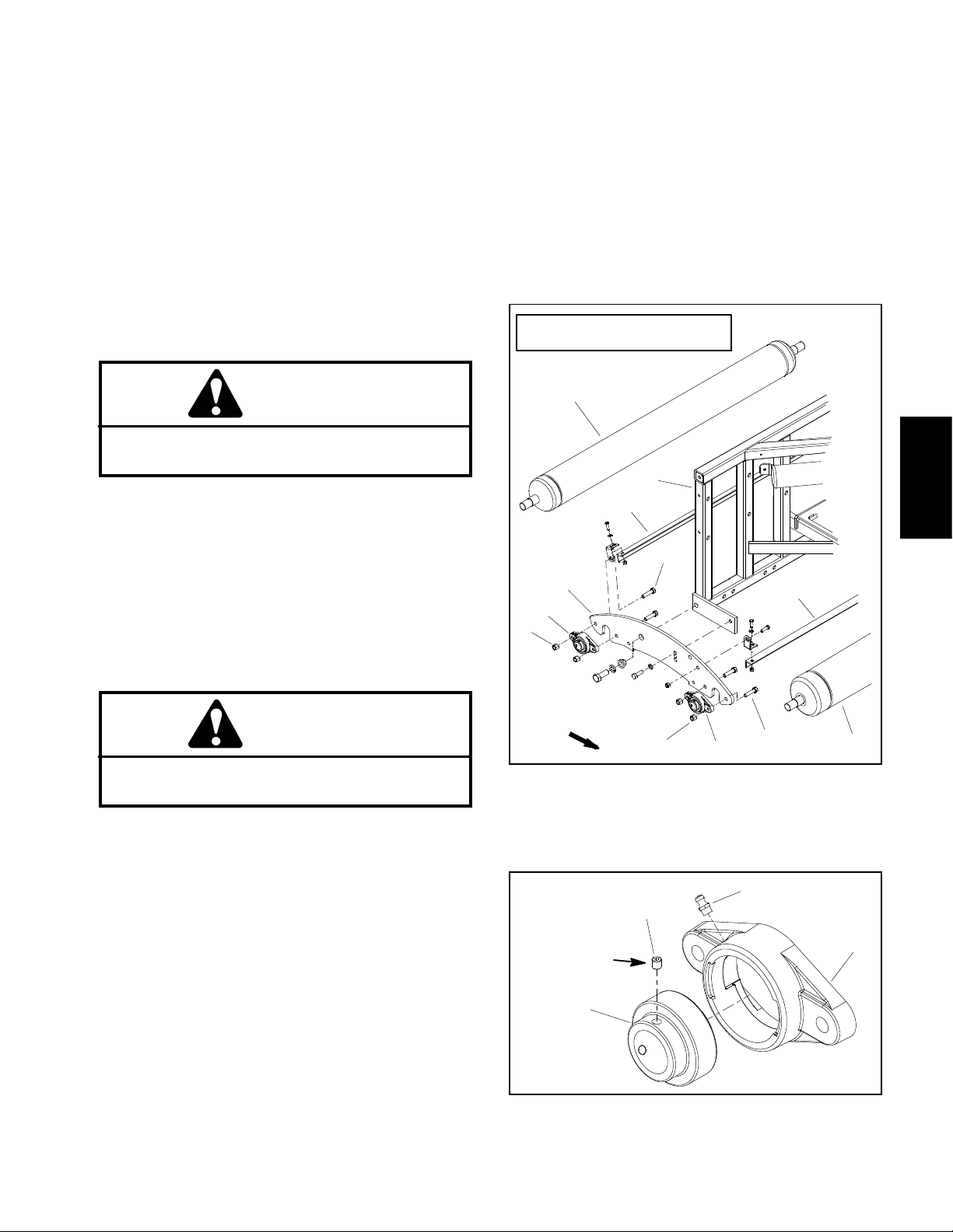
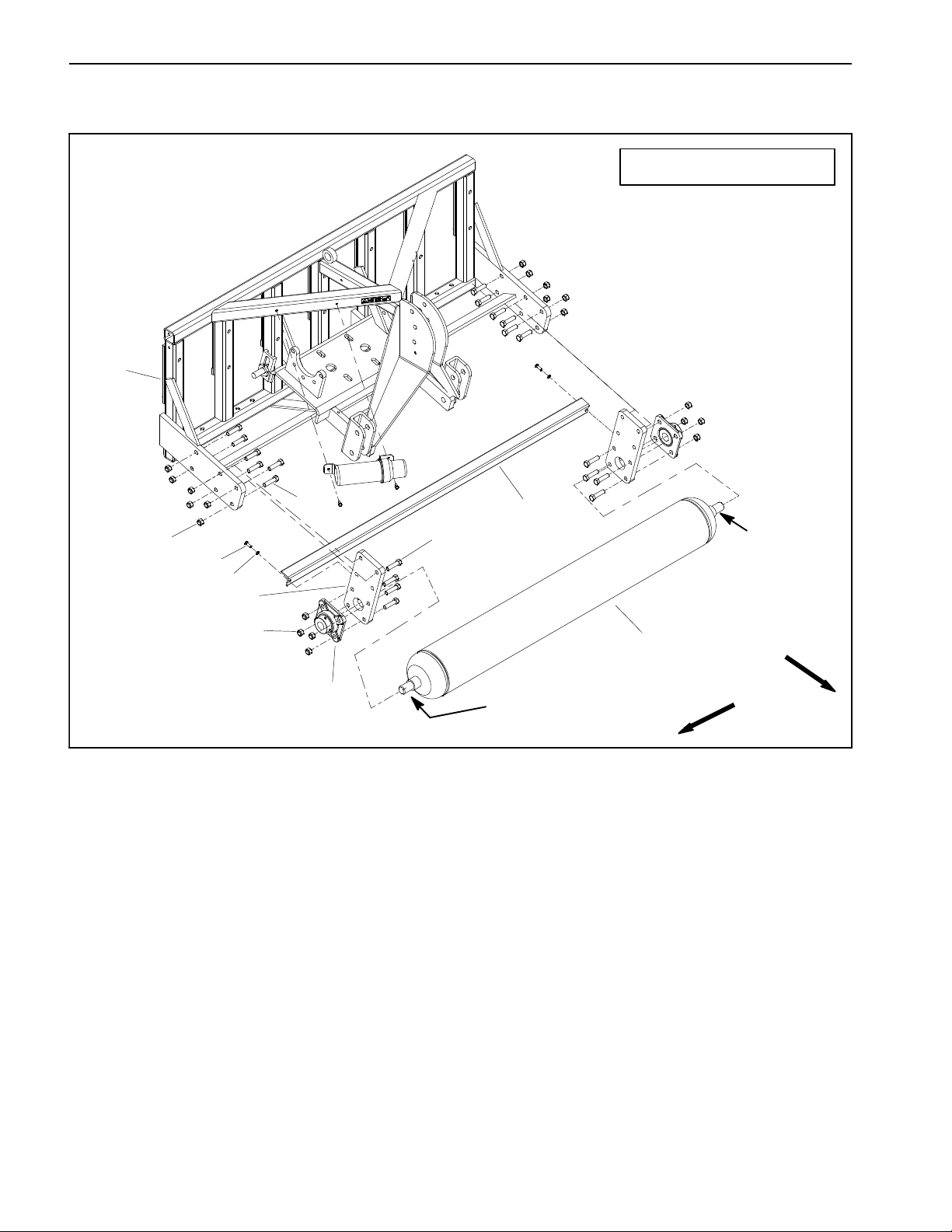
Roller (ProCore SR54, SR54--S, SR70 and SR70--S)
PROCORE SR54 SHOWN
1
12
13
14
7
6
5
4
8
9
3
2
10
11
ANTISEIZE
LUBRICANT
ANTISEIZE
LUBRICANT
1. Aerator frame
2. Flange bearing (2 used)
3. Lock nut (2 used per bearing)
4. Roller
5. Single roller boot (2 used)
6. Lock washer (2 used)
7. Cap screw (2 used)
8. Lock washer (2 used)
9. Cap screw (2 used)
10. Scraper
NOTE: ProCore SR54 and SR 70 aerators use a single
roller with two (2) bolt flange bearings (Fig. 1). Models
SR54--S and SR70--S use two (2) rollers each supported with two (2) bolt flange bearings (Fig. 2). The procedure for removal and installation of the rollers is the
same. The ProCore SR54 is shown in Figure 1.
FRONT
RIGHT
Figure 1
11. Cap screw (2 used per bearing)
12. Cap screw (2 used)
13. Lock washer (2 used)
14. Flat washer (2 used)
Roller Removal (Fig. 1)
1. Position aerator on a firm, level surface with aerator
attached to tractor. Disengage PTO, apply tractor parking brake, stop engine and remove key from the ignition
switch.
2. Support aerator to prevent it from moving.
3. Chock roller to prevent it from moving.
ProCore SR SeriesPage 3 -- 2Chassis
Page 21
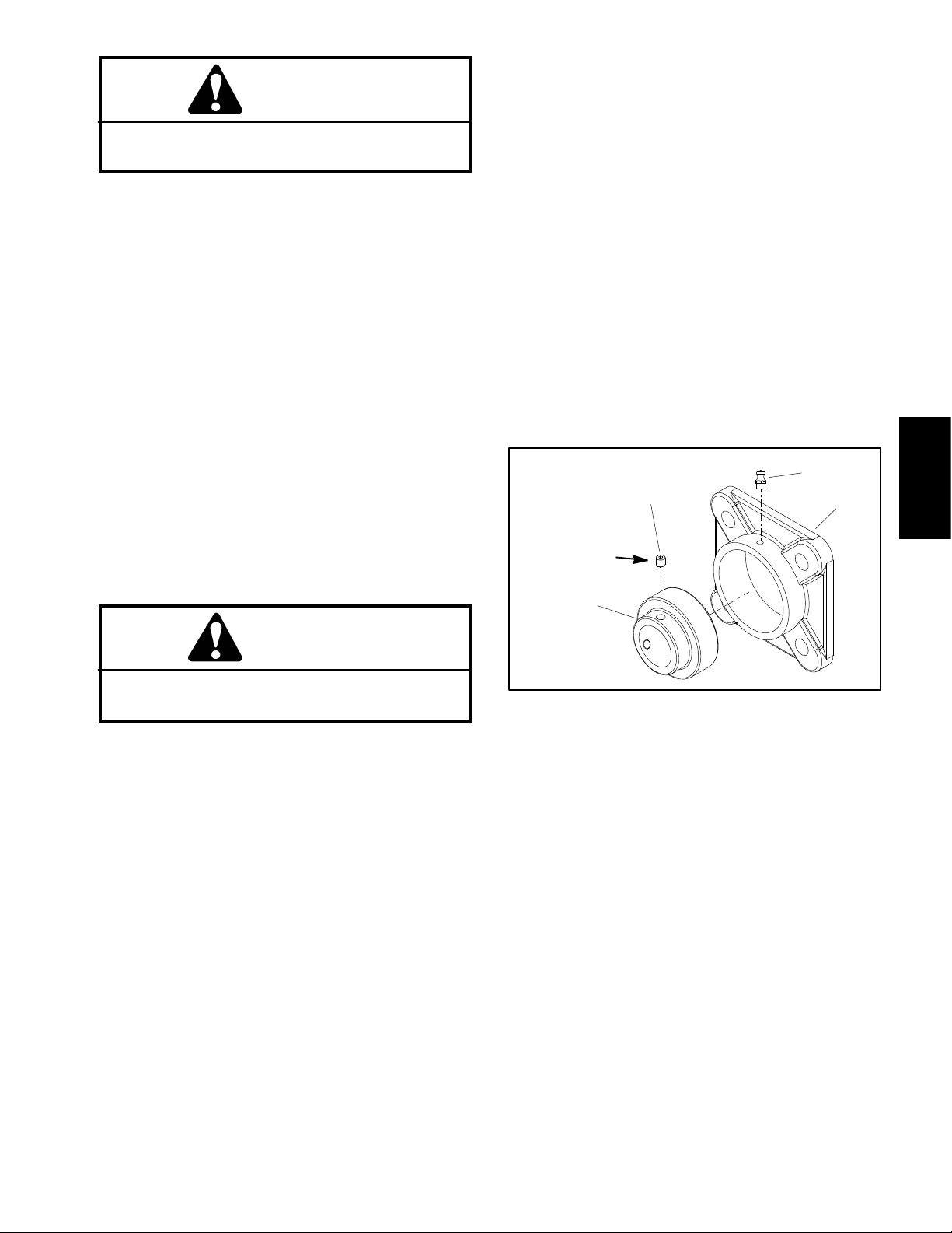
4. Loosen two (2) set screws that secure each bearing
locking collar to roller shaft (Fig. 3).
NOTE: On ProCore SR54--S and SR70--S aerators,
the rear roller scraper is secured to the frame with cap
screws that also secure the rear roller flange bearings.
When removing the rear roller on these aerators, the
roller scraper will be removed as well.
5. Remove cap screws and lock nuts that secure both
flange bearings (item 2) to aerator frame.
4. Align holes in bearing flanges with holes in roller boot
on aerator frame. Orientate bearing so that grease fittings point to front of aerator. Secure both flange bearings to frame with cap screws and lock nuts.
5. Check that roller is free to rotate and no binding exists. Center roller between bearings.
6. Apply Loctite #242 (or equivalent) to threads of bearing set screws. Tighten two (2) set screws to secure
each bearing locking collar to roller shaft ends.
6. Start engine on tractor. Slowly raise aerator while allowing roller to remain on the ground. Stop tractor engine and remove key from the ignition switch. Support
raised aerator to prevent it from lowering unexpectedly.
CAUTION
To prevent personal injury,make sure that roller
is supported as it is removed from the machine.
7. Remove roller with flange bearings from under machine.
8. Slide bearings from roller shaft ends.
Roller Installation (Fig. 1)
1. Clean roller shaft ends and apply antiseize lubricant
to shaft ends. Slide bearings onto roller shaft ends. Do
not tighten set screws in bearings at this time.
CAUTION
To prevent personal injury,make sure that roller
is supported as it is installed to the machine.
2. Position roller with flange bearings under raised aerator.
7. Lubricate grease fittings on bearings.
PROCORE SR54--S SHOWN
1
7
8
3
6
4
5
FRONT
5
4
3
Figure 2
1. Back roller
2. Main roller
3. Cap screw
4. Flange bearing
5. Lock nut
6. Double roller boot
7. Aerator frame
8. Roller scraper
Chassis
8
2
NOTE: Drop speed can be adjusted on the tractor. Refer to the Tractor Operator’s Manual for additional infor-
3
4
mation.
2
3. Start engine on tractor. Slowly lower aerator to posi-
Loctite #242
tion aerator frame to roller assembly. Stop tractor engine
and remove key from the ignition switch.
1
NOTE: On ProCore SR54--S and SR70--S aerators,
make sure to install the rear roller scraper when installing the flange bearings.
Figure 3
1. Bearing
2. Bearing housing (2 bolt)
3. Set screw (2 used)
4. Grease fitting
ProCore SR Series Page 3 -- 3 Chassis
Page 22
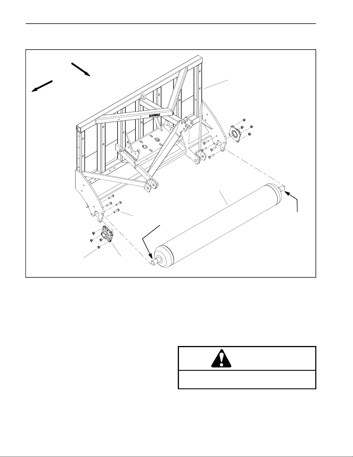
Roller (ProCore SR48 and SR72)
1
PROCORE SR72 SHOWN
4
6
9
8
7
6
5
1. Aerator frame
2. Scraper
3. Roller
4. Cap screw
5. Flange bearing (2 used)
6. Lock nut
NOTE: The roller used on the ProCore SR48 and SR72
are very similar. The procedure for removal and installation of the roller is the same for both models. The ProCore SR72 is shown in Figure 4.
Roller Removal (Fig. 4)
1. Position aerator on a firm, level surface with aerator
attached to tractor. Disengage PTO, apply tractor parking brake, stop engine and remove key from the ignition
switch.
4
Figure 4
2
ANTISEIZE
LUBRICANT
3
ANTISEIZE
LUBRICANT
7. Vertical roller bar (2 used)
8. Lock washer (2 used)
9. Cap screw (2 used)
FRONT
RIGHT
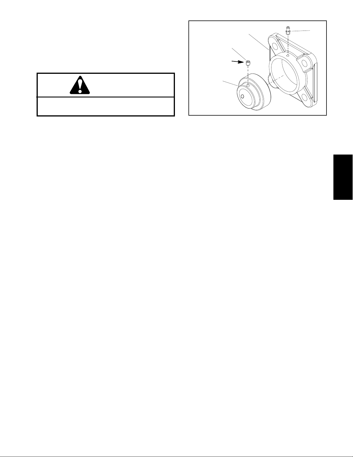
4. Loosen two (2) set screws that secure each bearing
locking collar to roller shaft (Fig. 5).
5. Remove four (4) cap screws and lock nuts that secure both vertical roller bars (item 7) to aerator frame.
6. Start engine on tractor. Slowly raise aerator while allowing roller assembly to remain on the ground. Stop
tractor engine and remove key from the ignition switch.
Support raised aerator to prevent it from lowering unexpectedly.
2. Support aerator to prevent it from moving.
3. Chock roller to prevent it from moving.
ProCore SR SeriesPage 3 -- 4Chassis
Page 23
CAUTION
NOTE: Drop speed can be adjusted on the tractor. Re-
fer to the Tractor Operator’s Manual for additional information.
To prevent personal injury,make sure that roller
is supported as it is removed from the machine.
7. Remove roller with vertical roller b ars and flange
bearings from under machine.
8. Slide vertical roller bars and flange bearings from
roller shaft ends.
9. If necessary, remove four (4) cap screws and lock
nuts that secure flange bearings to vertical roller bars.
Separate bearings from roller bars.
Roller Installation (Fig. 4)
1. If bearings were removed from vertical roller bars,
position flange bearings to roller bars so that bearing
grease fittings will point to front of aerator after installation. Secure bearings to roller bars with four (4) cap
screws and lock nuts.
2. Clean roller shaft ends and apply antiseize lubricant
to shaft ends. Slide vertical roller bar and flange bearing
assemblies onto roller shaft ends. Do not tighten set
screws in bearings at this time.
4. Start engine on tractor. Slowly lower aerator to position aerator frame to roller assembly.Stop tractor engine
and remove key from the ignition switch.
5. Align holes in vertical roller bars with holes in aerator
frame. Make sure that bearing grease fittings point to
front of aerator. Secure both roller bars to frame with four
(4) cap screws and lock nuts.
6. Check that roller is free to rotate and no binding exists. Center roller between bearings.
7. Apply Loctite #242 (or equivalent) to threads of bearing set screws. Tighten two (2) set screws to secure
each bearing locking collar to roller shaft.
8. Lubricate grease fittings on bearings.
4
3
Loctite #242
1
2
Chassis
CAUTION
To prevent personal injury,make sure that roller
is supported as it is installed to the machine.
3. Position roller with vertical roller bars and flange bearings under raised aerator.
Figure 5
1. Bearing
2. Bearing housing (4 bolt)
3. Set screw (2 used)
4. Grease fitting
ProCore SR Series Page 3 -- 5 Chassis
Page 24
Roller (ProCore SR75)
FRONT
RIGHT
1
2
3
ANTISEIZE
LUBRICANT
ANTISEIZE
LUBRICANT
5
1. Aerator frame
2. Roller
4
3. Cap screw (4 used per bearing)
4. Flange bearing (2 used)
Roller Removal (Fig. 6)
1. Position aerator on a firm, level surface with aerator
attached to tractor. Disengage PTO, apply tractor parking brake, stop engine and remove key from the ignition
switch.
2. Support aerator to prevent it from moving.
3. Chock roller to prevent it from moving.
4. Loosen two (2) set screws that secure each bearing
locking collar to roller shaft (Fig. 7).
5. Remove four (4) cap screws and lock nuts that secure flange bearings (item 4) to aerator frame.
Figure 6
5. Lock nut (4 used per bearing)
6. Start engine on tractor. Slowly raise aerator while allowing roller assembly to remain on the ground. Stop
tractor engine and remove key from the ignition switch.
Support raised aerator to prevent it from lowering unexpectedly.
CAUTION
To prevent personal injury, make sure that roller
is supported as it is removed from the machine.
7. Remove roller with flange bearings from under machine.
ProCore SR SeriesPage 3 -- 6Chassis
Page 25
8. Slide flange bearings from roller shaft ends.
Roller Installation (Fig. 6)
1. Clean roller shaft ends and apply antiseize lubricant
to shaft ends. Slide flange bearing onto roller shaft ends.
Do not tighten set screws in bearings at this time.
CAUTION
To prevent personal injury,make sure that roller
is supported as it is installed to the machine.
2. Position roller with flange bearings under raised aerator.
NOTE: Drop speed can be adjusted on the tractor. Refer to the Tractor Operator’s Manual for additional information.
3. Start engine on tractor. Slowly lower aerator to position aerator frame to roller assembly. Stop tractor engine
and remove key from the ignition switch.
2
3
Loctite #242
1
Figure 7
1. Bearing
2. Bearing housing (4 bolt)
4
3. Set screw (2 used)
4. Grease fitting
Chassis
4. Align holes in flange bearings with holes in aerator
frame. Make sure that bearing grease fittings point to
front of aerator. Secure both bearings to frame with four
(4) cap screws and lock nuts.
5. Check that roller is free to rotate and no binding exists. Center roller between bearings.
6. Apply Loctite #242 (or equivalent) to threads of bearing set screws. Tighten two (2) set screws to secure
each bearing locking collar to roller shaft.
7. Lubricate grease fittings on bearings.
ProCore SR Series Page 3 -- 7 Chassis
Page 26
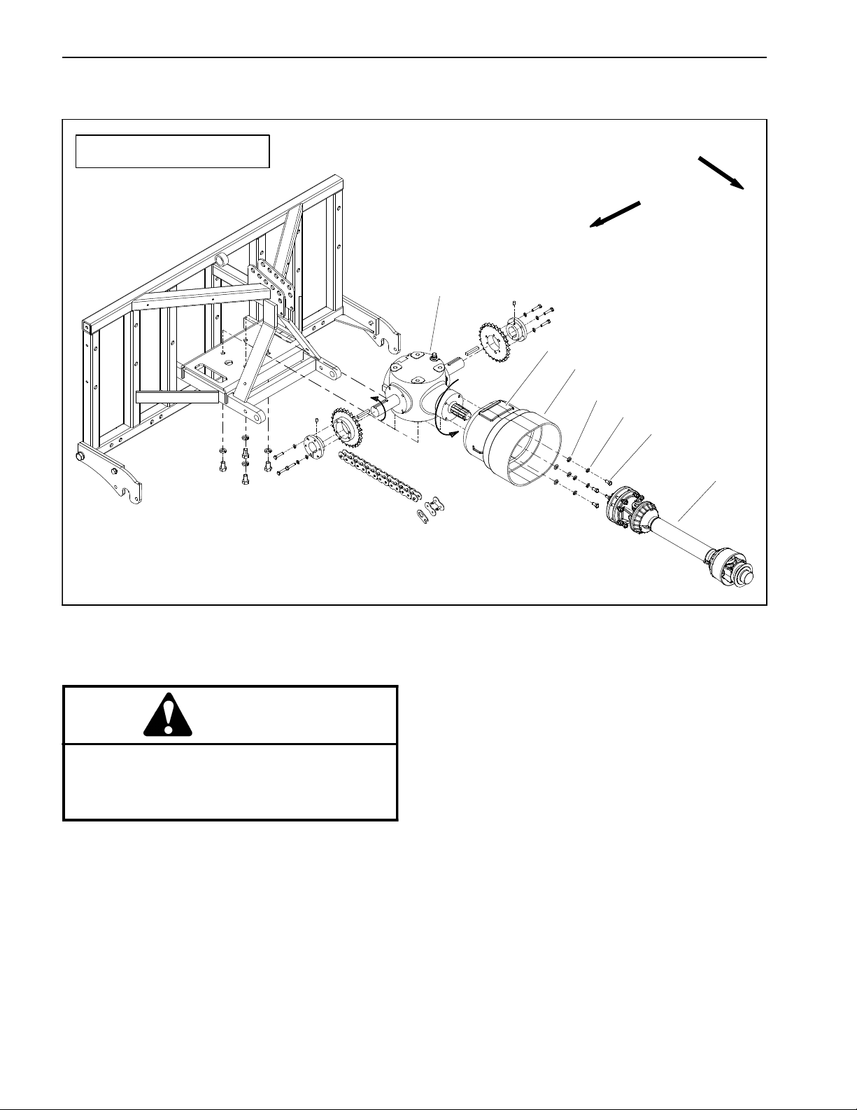
PTO Driveshaft
PROCORE SR54 SHOWN
FRONT
RIGHT
1
2
3
4
5
6
7
1. Gearbox
2. Driveshaft shield access panel
3. PTO driveshaft shield
4. Flat washer (4 used)
5. Lock washer (4 used)
CAUTION
The friction clutch on the PTO driveshaft may
become hot during use. To prevent personal injury, make sure that clutch has cooled before
performing any service on the driveshaft.
Removal (Fig. 8)
1. Position aerator on a firm, level surface. If aerator is
attached to tractor, disengage PTO, apply tractor parking brake, stop engine and remove key from the ignition
switch.
2. Unhook driveshaft shield safety chains from the tractor and the aerator driveshaft shield.
3. Support PTO driveshaft to prevent it from falling.
Figure 8
6. Cap screw (4 used)
7. PTO driveshaft
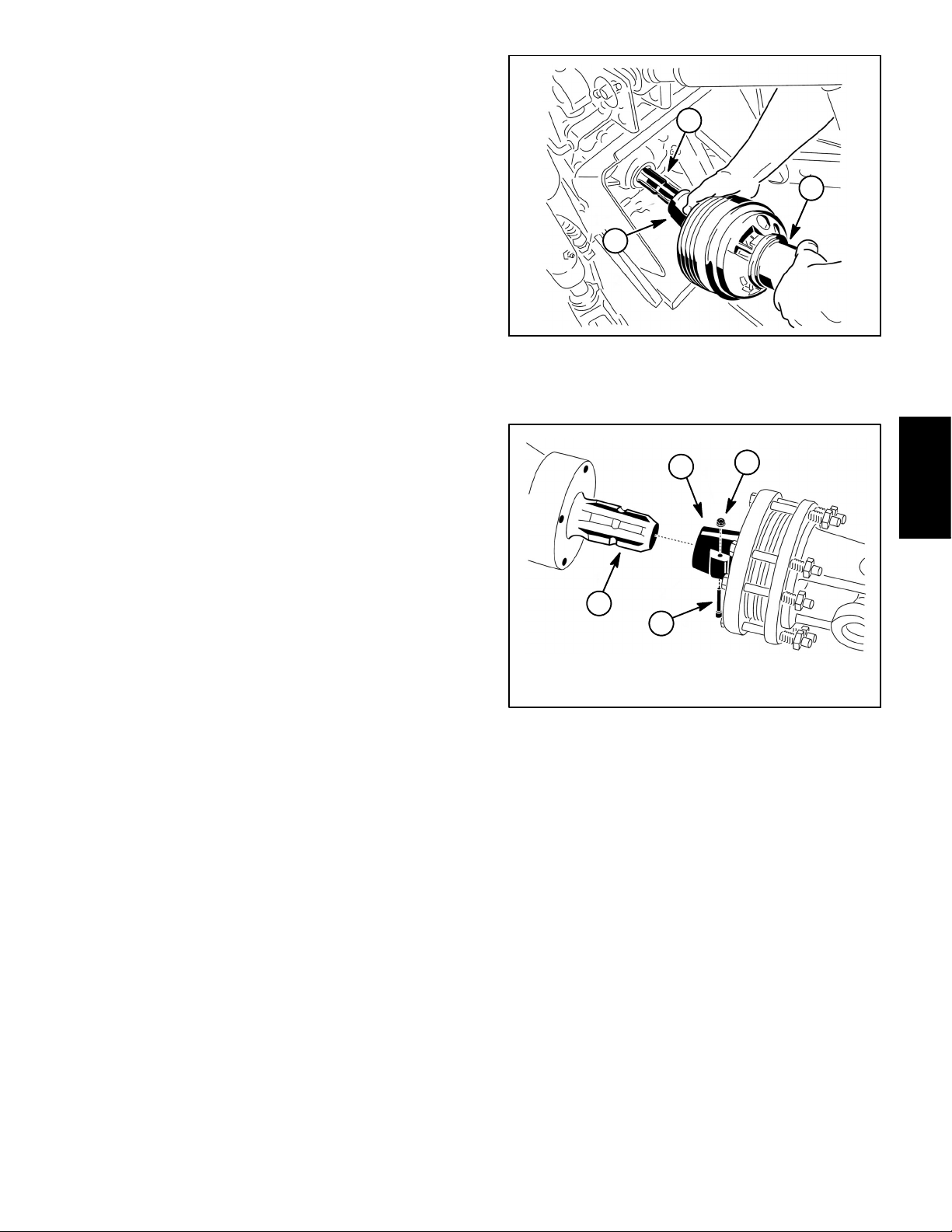
4. Separate PTO driveshaft from tractor PTO shaft (Fig.
9):
A. Pull back on locking collar to release driveshaft
from PTO shaft.
B. Slide driveshaft yoke from PTO shaft.
5. Separate PTO driveshaft from gearbox input shaft
(Fig. 10):
A. Open driveshaft shield a ccess panel to be able to
reach PTO driveshaft coupler.
B. Remove pin and lock nut from PTO driveshaft
coupler at aerator gearbox input shaft.
C. Slide driveshaft coupler from gearbox shaft.
6. Remove driveshaft from machine.
ProCore SR SeriesPage 3 -- 8Chassis
Page 27
Installation (Fig. 8)
1. Apply grease to gearbox input shaft and tractor output shaft.
2. Position PTO driveshaft with clutch end toward aerator gearbox.
3. Secure PTO driveshaft coupler to gearbox input
shaft (Fig. 10):
A. Align splines of driveshaft coupler with gearbox
input shaft and slide coupler onto shaft.
B. Secure driveshaft coupler to gearbox input shaft
with pin and nut.
2
1
3
C. Close and secure driveshaft shield access panel.
4. Secure PTO driveshaft to tractor PTO shaft (Fig. 9):
A. Align splines of driveshaft yoke with tractor PTO
shaft and slide yoke onto shaft as far as possible.
B. Pull back on yoke so that locking collar secures
driveshaft to PTO shaft.
C. Check that driveshaft yoke is properly locked by
sliding yoke on PTO shaft.
5. Lubricate driveshaft grease fittings.
6. Connect driveshaft shield safety chains to the tractor
and the aerator driveshaft shield. Make sure that chains
remain slack when the aerator is raised or lowered.
Figure 9
1. Driveshaft
2. Tractor PTO shaft
1
2
3
Note: PTO driveshaft shield is
not shown in this illustration.
Figure 10
1. Driveshaft coupler
2. Gearbox input shaft
3. Locking collar
4
Chassis
3. Pin
4. Nut
ProCore SR Series Page 3 -- 9 Chassis
Page 28
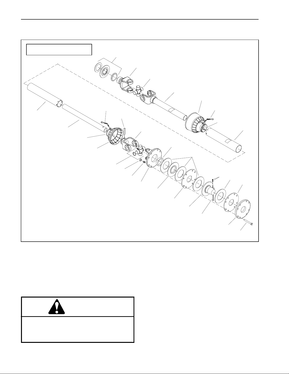
PTO Driveshaft Clutch Service
PROCORE SR72 SHOWN
19
18
24
20
21
11
8
8
13
26
3
2
10
16
12
23
4
24
25
1
15
9
4
5
7
5
22
14
6
17
1. Lock nut
2. Inner tube yoke
3. Inner tube
4. PTO clutch lining
5. Pressure plate
6. PTO pressure plate
7. Driving plate
8. Safety chain
9. Flange yoke
10. Outer tube cover
11. Inner tube cover
12. Bushing
13. Roll pin
14. Screw
15. Spring (8 used)
16. Connector
17. Cap screw (8 used)
18. Yoke
CAUTION
The friction clutch on the PTO driveshaft may
become hot during use. To prevent personal injury, make sure that clutch has cooled before
performing any service on the driveshaft.
Figure 11
19. Ball and collar kit
20. Yoke with tube
21. Cone shield (tractor side)
22. Splined hub
23. Cone shield (clutch side)
24. Cross and bearing kit
25. Nut (8 used)
26. Connector
NOTE: The PTO driveshaft used on SR48, SR54,
SR54--S, SR70 and SR70--S aerators include two (2)
clutch linings and fewer driveshaft components on the
aerator end of the PTO driveshaft (Fig. 12). Driveshaft
clutch service for all ProCore SR models is similar.
ProCore SR SeriesPage 3 -- 10Chassis
Page 29

Clutch Disassembly (Fig. 11)
1. Position aerator on a firm, level surface. If aerator is
attached to tractor, disengage PTO, apply tractor parking brake, stop engine and remove key from the ignition
switch.
2. Remove PTO driveshaft from aerator (see PTO Driveshaft Removal in this section).
3. Remove eight (8) cap screws (item 17), nuts (item
25) and springs (item 15) that secure clutch assembly to
driveshaft flange yoke.
PROCORE SR54 SHOWN
2
2
4
3
4. Remove clutch components from driveshaft using
Figure 11 as a guide.
Clutch Assembly (Fig. 11)
1. Assemble clutch components to driveshaft using
Figure 11 as a guide.
2. Secure clutch components with eight (8) cap screws
(item 17), springs (item 15) and nuts (item 25). Tighten
nuts so that spring length is 1.125” (28.6 mm) (Fig. 13).
3. Install PTO driveshaft to aerator (see PTO Driveshaft
Installation in this section).
IMPORTANT: DO NOT overtighten nuts that tension
clutch springs on PTO driveshaft. Driveshaft clutch
is designed to slip if drive system is over--loaded. If
nuts are overtightened, driveshaft or tractor transmission damage may occur.
4. After installation is complete, check that clutch does
not slip. If clutch is slipping, tighten nuts equally in 1/4
turn increments until clutch slippage ceases.
1. PTO pressure plate
2. PTO clutch lining
4
1
Figure 12
3. PTO flange hub
4. Flange yoke
1.125” (28.6 mm)
Chassis
1
2
3
Figure 13
1. Cap screw
2. Spring
3. Nut
4. Flange yoke
ProCore SR Series Page 3 -- 11 Chassis
Page 30
PTO Driveshaft Cross and Bearing Service
1. Remove PTO driveshaft from aerator (see PTO Driveshaft Removal in this section).
2. If necessary, separate PTO driveshaft and remove
shields.
IMPORTANT: When placing yoke in vise, clamp
lightly on the solid part of the yoke to prevent yoke
damage. Also, the use of a vise with soft jaws is recommended.
3. Lightly clamp yoke in vise with soft jaws. Remove
snap rings that secure bearings in each yoke. Remove
yoke from vise.
IMPORTANT: To prevent damage to driveshaft
yokes, support yokes when removing and installing
bearings.
4. Use a press to remove cross and bearings from
yokes:
A. Place a small socket against one bearing and a
large socket against the yoke on the opposite side.
B. While supporting the large socket, apply pressure on small socket to partially push the opposite
bearing into the large socket.
D. Hold cross in alignment and press bearing in until
it hits the yoke.
E. Carefully place second bearing into yoke bore
and onto cross shaft. Press bearing into yoke.
F. Install snap rings to secure bearings in place.
G. Repeat procedure for other yoke.
H. Grease cross until grease comes out of all four (4)
bearing cups.
6. Make sure that assembled joint moves without binding. Slight binding can usually be eliminated by lightly
rapping the yoke lugs with a soft faced hammer. If binding continues, disassemble joint to identify source of
binding.
7. If driveshaft was separated for cross and bearing
service, install shields and assemble driveshaft halves.
8. Install PTO driveshaft to aerator (see PTO Driveshaft
Installation in this section).
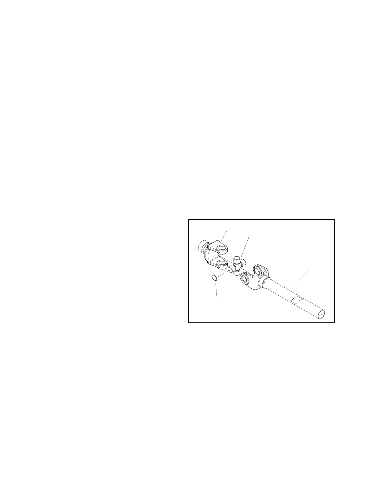
1
2
C. Remove yoke from press, grasp partially removed bearing and tap on yoke to completely remove the bearing.
D. Repeat process for remaining bearings.
E. Thoroughly clean and inspect all components.
5. To install new cross and bearings:
A. Apply a coating of grease to bearing bores of end
yoke and shaft yoke. Also, apply grease to bearings
and seal of bearing assembly. Make sure that all
bearing rollers are properly seated in bearing cage.
B. Press one bearing partially into yoke.
IMPORTANT: Take care when installing cross
into bearing to avoid damaging bearing seal.
C. Carefully insert cross into bearing and yoke.
3
1. End yoke
2. Cross and bearing kit
4
Figure 14
3. Snap ring (4 used)
4. Shaft yoke
ProCore SR SeriesPage 3 -- 12Chassis
Page 31

Hydraulic Top Link
16
1
18
2
3
5
6
20
16
17
7
19
2
8
11
Chassis
4
13
9
For machine serial numbers below 320000000
Figure 15
1. Shaft
2. Cap screw (2 used)
3. Retainer plate
4. Retaining ring
5. Wiper
6. Head
7. Back--up ring
8. O-- ring
9. Back--up ring
10. O--ring
11. Bac k - -up ri ng
12. O--ring
13. Piston
14. O--ring
Disassembly (Fig. 15)
1. Remove hydraulic top link from aerator and tractor
(Fig. 17).
2. Remove spacers (item 16) from cylinder shaft clevis
and adapter on barrel end.
10
12
14
15
15. Lock nut
16. Spacer
17. Adapter
18. Barrel
19. Pin
20. Cotter pin
3. Remove oil from hydraulic cylinder into a drain pan
by slowly pumping the cylinder shaft. Plug both cylinder
ports and clean the outside of the cylinder.
4. Remove two (2) cap screws that secure retainer
plate to head. Position plate away from cylinder barrel
to allow access to retaining ring (item 4).
ProCore SR Series Page 3 -- 13 Chassis
Page 32

13
14
7
6
5
4
3
2
12
11
10
9
9
8
For machine serial numbers above 320000000
Figure 16
1. Shaft
2. Head
3. Dust seal
4. Seal
5. Dual seal
6. Wear ring
7. Piston
8. O-- ring
9. Seal
10. Lock nut
5. Removeretainingringfromgrooveinbarrel.
6. Extract shaft, head and piston assembly by carefully
twisting and pulling on the shaft.
IMPORTANT: Do not clamp vise jaws against the
shaft surface. Clamp on th e shaft clevis ONLY.
7. Mount shaft securely in a vise by clamping on the clevis of the shaft. Remove lock nut and piston from the
shaft. Carefully slide head and retainer plate off the
shaft.
1
11. Barrel
12. Pin
13. Cotter pin
14. Clevis
Inspection
CAUTION
Use eye protection such as goggles when using
compressed air to dry cylinder components.
1. Wash all cylinder components in clean solvent. Dry
parts with compressed air.
8. Taking care to not scratch or damage components,
remove and discard wiper, back--up rings and O--rings
from head and piston.
2. Inspect internal surface of barrel for deep scratches,
out--of--roundness and bending. Replace if worn or
damaged.
ProCore SR SeriesPage 3 -- 14Chassis
Page 33

3. Inspect head, shaft and piston for excessive pitting,
scoring and wear. Replace any worn or damaged parts.
Assembly (Fig. 15)
1. Make sure all hydraulic cylinder parts are clean before assembly.
2. Coat new O--rings, back--up rings and wiper with
clean hydraulic oil. Carefully install new back--up rings,
O--rings and wiper to head and piston.
8
9
FRONT
1
2
IMPORTANT: Do not clamp vise jaws against the
shaft surface. Clamp on the shaft clevis ONLY.
3. Mount shaft securely in a vise by clamping on the clevis of the shaft.
A. Coat shaft with clean hydraulic oil.
B. Slide retainer plate and then head onto the shaft.
Make sure that threaded holes in head are toward
the retainer plate location.
C. Install piston onto the shaft and secure with lock
nut.
D. Remove shaft assembly from the vise.
4. Coat all internal parts with a light coat of clean hydraulic oil. Slide shaft, head and piston assembly into
the barrel being careful not to damage the seals.
5. Secure head in barrel with retaining ring. Make sure
that retaining ring is fully seated in groove in barrel.
5
5
4
7
6
3
Figure 17
1. Hydraulic top link
2. Adapter
3. Pin
4. Cotter pin
5. Spacer
6. Hydraulic hose
7. Hydraulic hose
8. Link
9. Lynch pin
6. Pull shaft so that head is at top of barrel. Position retainer plate to barrel and head. Secure retainer plate
with two (2) cap screws.
7. Slide spacers (item 16) into cylinder shaft clevis and
adapter on barrel end.
8. Install h ydraulic top link to aerator and tractor (Fig.
17).
Chassis
ProCore SR Series Page 3 -- 15 Chassis
Page 34

Covers (ProCore SR54, SR54--S, SR70 and SR70--S)
PROCORE SR54 SHOWN
1
2
9
16
8
3
15
10
13
13
12
11
12
14
3
6
12
10
12
7
4
Figure 18
1. Rear hood
2. Cap screw (2 used)
3. Latch (2 used)
4. Cap screw (4 used)
5. RH screen
6. LH screen
7. Lock washer (6 used)
8. Foam strip (2 used)
9. Spacer (2 used per screen)
10. Cap screw (4 used)
11. Screen clip (2 used)
NOTE: The covers used on the ProCore SR54,
SR54--S, SR70 and SR70--S are very similar. The procedure for removal and installation of the covers is the
same on these models. The ProCore SR54 is shown in
Figure 18.
11
5
12. Flat washer (10 used)
13. Lock nut (4 used)
14. Cap screw (2 used)
15. Socket head screw (4 used)
16. Lock nut (4 used)
FRONT
RIGHT
ProCore SR SeriesPage 3 -- 16Chassis
Page 35

Removal (Fig. 18)
Installation (Fig. 18)
1. Position aerator on a firm, level surface. If aerator is
attached to tractor, disengage PTO, apply tractor parking brake, stop engine and remove key from the ignition
switch.
2. If necessary, remove rear hood:
A. Unlatch rear hood.
B. Remove two (2) cap screws (item 2) that secure
rearhoodtoframe.
C. Remove rear hood from machine.
3. To remove front screen (item 5 or 6):
A. Unlatch, raise and support rear hood if it is attached to frame.
B. Support front screen to prevent it from falling.
C. Remove cap screw, lock nut and two (2) flat
washers that secure front screen to screen clip (item
11) .
D. Remove cap screw, lock washer and flat washer
that secure front screen to frame.
1. Make sure that screen clip (item 11) is loosely attached to frame.
2. To install front screen (item 5 or 6):
A. Position front screen to machine.
B. Place two (2) spacers (item 9) between screen
and frame. Install two (2) cap screws and lock washerstosecurefrontscreentoframe.
C. Secure front screen to screen clip (item 11) with
cap screw, lock nut and two (2) flat washers.
D. Secure front screen tab to frame with cap screw,
lock washer and flat washer.
3. If removed, secure rear hood to machine with two (2)
cap screws (item 2).
4. Lower and secure rear hood.
Chassis
E. Remove two (2) cap screws and flat washers that
secure front screen to frame. Retrieve two (2)
spacers (item 9) from between screen and frame.
F. Remove front screen from machine.
ProCore SR Series Page 3 -- 17 Chassis
Page 36

Covers (ProCore SR48 and SR72)
PROCORE SR72 SHOWN
1
13
12
15
5
4
12
15
11
9
8
14
10
9
15
9
6
14
16
6
7
14
16
3
8
2
Figure 19
1. Rear hood
2. RH screen
3. LH screen
4. Foam strip (2 used)
5. Spacer (4 used)
6. Top screen clip (2 used)
7. Front screen bracket (2 used)
8. Cap screw (8 used)
9. Cap screw (8 used)
10. Socket head screw (4 used)
11. Lock nut (4 used)
NOTE: The covers used on the ProCore SR48 and
SR72 are very similar. The procedure for removal and
installation of the covers is the same on these models.
The ProCore SR72 is shown in Figure 19.
FRONT
7
12. Latch assembly (2 used)
13. Cap screw (2 used)
14. Flat washer (12 used)
15. Lock washer (8 used)
16. Lock nut (8 used)
RIGHT
ProCore SR SeriesPage 3 -- 18Chassis
Page 37

Removal (Fig. 19)
Installation (Fig. 19)
1. Position aerator on a firm, level surface. If aerator is
attached to tractor, disengage PTO, apply tractor parking brake, stop engine and remove key from the ignition
switch.
2. If necessary, remove rear hood:
A. Unlatch rear hood.
B. Remove two (2) cap screws (item 13) that secure
rearhoodtoframe.
C. Remove rear hood from machine.
3. To remove front screen (item 2 or 3):
A. Unlatch, raise and support rear hood if it is attached to frame.
B. Support front screen to prevent it from falling.
C. Remove cap screws and lock washers that secure top screen clip (item 6) and front screen bracket
(item 7) to frame.
D. Remove two (2) cap screws and lock washers
that secure front screen to frame channels. Retrieve
two (2) spacers (item 5) from between screen and
frame.
1. If removed, secure top screen clip (item 6) and front
screen bracket (item 7) to front screen.
2. To install front screen (item 2 or 3):
A. Position front screen to machine.
B. Place two (2) spacers (item 5) between screen
and frame. Install two (2) cap screws and lock washers to secure front screen to frame channels.
C. Secure top screen clip (item 6) and front screen
bracket (item 7) to frame with cap screws and lock
washers.
3. If removed, secure rear hood to machine with two (2)
cap screws (item 13).
4. Lower and secure rear hood.
Chassis
E. Remove front screen from machine.
4. If necessary, remove top screen clip (item 6) and
front screen bracket (item 7) from front screen.
ProCore SR Series Page 3 -- 19 Chassis
Page 38

Covers (ProCore SR75)
5
12
2
5
6
8
FRONT
1
5
6
5
6
6
10
3
6
5
4
9
5
11
6
5
6
5
RIGHT
Figure 20
1. Rear hood
2. Cap screw (2 used)
3. LH end cover
4. LH front screen
5. Lock washer (38 used)
6. Cap screw (36 used)
7. RH front screen
8. RH end cover
Removal (Fig. 20)
1. Position aerator on a firm, level surface. If aerator is
attached to tractor, disengage PTO, apply tractor parking brake, stop engine and remove key from the ignition
switch.
2. Remove rear hood and front screens using Figure 20
as a guide.
10
5
7
5
6
11
9. Window plate (2 used)
10. Spacer (2 used)
11. Hex nut (2 used)
12. Latch assembly (2 used)
Installation (Fig. 20)
1. Install rear hood and front screens using Figure 20
as a guide.
ProCore SR SeriesPage 3 -- 20Chassis
Page 39

Coring Head (SR54 & SR70)
Table of Contents
SPECIFICATIONS 2.............................
GENERAL INFORMATION 4.....................
Coring Head 4................................
Coring Head Adjustments 6....................
SPECIAL TOOLS 7.............................
SERVICE AND REPAIRS 8......................
Linkage Arm Assemblies 8.....................
Connecting Rods 10...........................
Coring Crankshaft (SR54) 12...................
Coring Crankshaft (SR70) 13...................
Coring Crankshaft Bearing Housings 14..........
Coring Head Drive Chain 18....................
Coring Head Drive Sprockets 20................
Gearbox 22..................................
Chapter 4
Coring Head
(SR54 & SR70)
ProCore SR Series Page 4 -- 1 Coring Head (SR54 & SR70)
Page 40

Specifications
Item Description
ProCore SR54
Aerating Width 54 inches (1.37 meters)
Number of Connecting Rods 6
Number of Rollers 1
Depth Adjustment Hydraulic Top Link
Gearbox Lubricant SAE 80W -- 90 gear lube
Gearbox Lubricant Capacity 2 US quart (1.9 liter)
Gearbox Weight (approximate) 80 lbs (36 kg)
ProCore SR54--S
Aerating Width 54 inches (1.37 meters)
Number of Connecting Rods 6
Number of Rollers 2
Depth Adjustment Fixed Top Link
Gearbox Lubricant SAE 80W -- 90 gear lube
Gearbox Lubricant Capacity 2 US quart (1.9 liter)
Gearbox Weight (approximate) 80 lbs (36 kg)
ProCore SR70
Aerating Width 73 inches (1.85 meters)
Number of Connecting Rods 8
Number of Rollers 1
Depth Adjustment Hydraulic Top Link
Gearbox Lubricant SAE 80W -- 90 gear lube
Gearbox Lubricant Capacity 2 US quart (1.9 liter)
Gearbox Weight (approximate) 109 lbs (50 kg)
ProCore SR70--S
Aerating Width 73 inches (1.85 meters)
Number of Connecting Rods 8
Number of Rollers 2
Depth Adjustment Fixed Top Link
Gearbox Lubricant SAE 80W -- 90 gear lube
Gearbox Lubricant Capacity 2 US quart (1.9 liter)
Gearbox Weight (approximate) 109 lbs (50 kg)
ProCore SR SeriesPage 4 -- 2Coring Head (SR54 & SR70)
Page 41

This page is intentionally blank.
Coring Head
(SR54 & SR70)
ProCore SR Series Page 4 -- 3 Coring Head (SR54 & SR70)
Page 42

General Information
Coring Head
PROCORE SR54
CORING HEAD
PROCORE SR70
CORING HEAD
6
4
8
6
7
2
1
3
5
1
4
6
8
6
2
7
1. Aerator frame
2. Coring crankshaft assembly
3. Tine holder
5
Figure 1
4. Connecting rod
5. Linkage arm assembly
6. Drive chain sprocket
3
7. Crank arm
8. Bearing holder
ProCore SR SeriesPage 4 -- 4Coring Head (SR54 & SR70)
Page 43

The coring head of a ProCore SR deep tine aerator consists of the aerator frame, a coring crankshaft assembly,
tine holders and aerating tines. The rotating crankshaft
assembly operates a number of connecting rods with
linkage arm assemblies to provide effective tine motion
for deep turf aeration. The SR54 and SR70 aerator
frames pivot on a single roller to allow aerating depth
control. The SR54--S and SR70--S aerators are
equipped with dual rollers.
Drive for the coring head is provided by the towing tractor PTO output shaft. A gearbox on the ProCore aerator
is rotated by a driveshaft connected to the tractor PTO
shaft. The aerator gearbox provides rotation for the coring head crankshaft assembly with two (2) drive c hains.
The drive chains are each tensioned by an adjustable
idler sprocket.
The coring crankshaft is composed of multiple crank
arms, bearings, bearing housings and crank shafts. The
crankshaft assembly is designed and assembled to ensure minimal vibration during aerator operation.
A variety of tines and tine heads are available for use on
ProCore SR Series aerators. Refer to the Operator’s
Manual for available options.
Coring Head
(SR54 & SR70)
ProCore SR Series Page 4 -- 5 Coring Head (SR54 & SR70)
Page 44

Coring Head Adjustments
See Operator’s Manual for adjustment procedures for
the coring head on your ProCore SR series aerator.
CAUTION
Never work on the aerator with the tow tractor
PTO engaged or engine running. Always disengage the PTO, stop tractor engine, remove key
from the ignition switch and wait for all machine
movement to stop before performing any service
to aerator components.
ProCore SR SeriesPage 4 -- 6Coring Head (SR54 & SR70)
Page 45

Special Tools
Order special tools from your Toro Distributor.
Crankshaft Nut Wrench
Use to remove and install the hex nuts that secure coring
head crankshaft crank arms and connecting rods.
Toro Part Number: SG885300
Bullet Tools
Use to protect threads of crankshaft components during
assembly of crankshaft, connecting rods and linkage
arms. The bullet tool should be installed onto the
threads of the crankpin or linkage arm fastener to prevent thread damage when component is installed.
NOTE: On ProCore SR54 and SR70 aerators, bullet
tool SG255001 is used for the crank pin and crank shaft.
Tool SG255002 is used for the cap screws that secure
the linkage arms.
3” hex
SG255000
13/8”-- 16
(1.745” OD)
SG255001
11/4”-- 12
(1.560” OD)
Figure 2
2” hex
Coring Head
(SR54 & SR70)
SG255002
3/4” -- 16
(0.980” OD)
Figure 3
Torque Multiplier
Use in conjunction with an appropriate torque wrench to
install and properly torque the fasteners that secure coring head crankshaft crank arms and connecting rods.
Obtain this tool locally.
Figure 4
ProCore SR Series Page 4 -- 7 Coring Head (SR54 & SR70)
Page 46

Service and Repairs
Linkage Arm Assemblies
FRONT
RIGHT
1
265 ft--lb
(359 N--m)
14
15
13
PROCORE SR54 SHOWN
ANTISEIZE
LUBRICANT
ANTISEIZE
5
6
LUBRICANT
3
21
22
23
24
3
9
2
17
2
4
16
8
18
8
20
7
28
4
10
14
11
12
13
7
6
22
27
1. Cap screw
2. Outer bushing
3. Cap screw
4. Linkage arm
5. Cap screw
6. Outer bushing
7. Ball bearing
8. Outer bushing
9. Connecting rod
10. Linkage spacer
Figure 5
11. Rubber bumper
12. Rubber bumper
13. Lock nut
14. Lock nut
15. Rear spring bracket
16. Rear spool assembly
17. Cap screw
18. Lock nut
19. Spring assembly
19
25
26
20. Rear spring spool
21. Head spacer
22. Flange bushing
23. Cap screw
24. Tine head
25. Set screw
26. Head spool
27. Lock nut
28. Head bumper
ProCore SR SeriesPage 4 -- 8Coring Head (SR54 & SR70)
Page 47

NOTE: The linkage arm assemblies for ProCore SR54
and SR70 aerators are very similar. The ProCore SR54
linkage arm assembly is shown in Figure 5. The tine
head assembly used on ProCore SR54--S and SR70--S
is shown in Figure 6.
Disassembly (Fig. 5)
1. Position aerator on a firm, level surface. If aerator is
attached to tractor, disengage PTO, apply tractor parking brake, stop engine and remove key from the ignition
switch.
2. Remove linkage arm components as needed using
Figures 5 and 6 as guides.
3. If necessary, disassemble rear spool assembly using Figure 7 as a guide.
4. Discard all r emoved bearings.
Assembly (Fig. 5)
1. If rear spool assembly was disassembled (Fig. 7):
A. Make sure that retaining rings are fully seated
into grooves in hinge housing.
B. Press a new bearing into one side of the hinge
housing until contacts installed retaining ring. Then
press second new bearing into housing so that it contacts first bearing.
C. Insert inner bushing into housing.
D. Press final two (2) new bearings into housing following above procedure.
16
12
16
13
4
12
6
1. Spring assembly
2. Head bumper
3. Lock nut
4. Flange bushing
5. Spring spool
6. Bolt
7. Cap screw
8. Lock washer
2
5
14
5
15
Figure 6
1
1
11
10
9. Set screw
10. Head adapter
11. Head spacer
12. Cap screw
13. Head bumper
14. Tube
15. Head spacer
16. Linkage arm
2
3
4
3
5
6
7
8
7
8
9
5
Coring Head
(SR54 & SR70)
2. If bearings (item 7) were removed from linkage arms,
press new bearings into arms.
NOTE: When installing cap screw (item 2), use bullet
tool SG255002 (see Special Toolsin this chapter) to pre-
3
3
4
2
vent thread damage to screw.
Figure 7
3. Assemble all linkage arm components using Figures
5 and 6 as guides.
1. Hinge housing
2. Bearing
3. Retaining ring
4. Inner bushing
5. Outer bushing
ProCore SR Series Page 4 -- 9 Coring Head (SR54 & SR70)
Page 48

Connecting Rods
FRONT
RIGHT
950 ft--lb
(1288 N--m)
14
13
265 ft--lb
(359 N--m)
12
11
1
ANTISEIZE
LUBRICANT
2
5
4
3
6
PROCORE SR54 SHOWN
4
5
9
10
8
7
3
6
7
8
1. Crank pin
2. Cap screw
3. Outer bushing
4. Retaining ring
5. Ball bearing
6. Outer bushing
7. Ball bearing
8. Retaining ring
9. Connecting rod
10. Bearing spacer
IMPORTANT: Before disassembling the coring
crankshaft, label location and orientation of components that are to be removed. Correct component
location and orientation are necessary for proper
aerator operation.
NOTE: The connecting rod assemblies for ProCore
SR54 and SR70 aerators are very similar. The ProCore
SR54 is shown in Figure 8.
Removal (Fig. 8)
1. Position aerator on a firm, level surface. If aerator is
attached to tractor, disengage PTO, apply tractor parking brake, stop engine and remove key from the ignition
switch.
Figure 8
11. Linkage arm
12. Lock nut
13. Clipped washer
14. Hex nut
2. Unlatch, open and support rear hood to allow access
to coring crankshaft.
3. Rotate coring crankshaft to allow access to crank pin
(item 1) and hex nut (item 14) for connecting rod to be
removed.
4. Insert block of wood between aerator frame and connecting rod to prevent the crankshaft from turning. Using
crankshaft nut wrench (see Special Tools), loosen, but
do not remove, hex nut (item 14).
5. Support connecting rod that is to be removed to prevent it from falling.
ProCore SR SeriesPage 4 -- 10Coring Head (SR54 & SR70)
Page 49

WARNING
As crankshaft components are removed from
machine, the crankshaft will become out of balance and may rotate quickly, creating pinch
points and potential for personal injury. Be cautious when disassembling the coring crankshaft.
B. Press a new bearing into one side of the connecting rod bore until the bearing contacts installed retaining ring. Then press second new bearing into
bore so that it contacts first bearing.
C. Insert bearing spacer into lower rod bore.
D. Press final two (2) new bearings into housing following above procedure. Make sure that bearing
spacer is centered in rod bore.
IMPORTANT: When removing cap screw (item 2)
and crank pin (item 1), note orientation for proper
assembly.
6. For connecting rod that is to be removed, remove
lock nut (item 12) and cap screw (item 2) that secure
lower end of connecting rod to linkage arms.
7. For connecting rod that is to be removed, remove
hex nut (item 14), clipped washer (item 13) and crank pin
(item 1) that secure upper end of connecting rod to coring crankarms.
8. Remove connecting rod from aerator. Locate and retrieve outer bushings (items 3 and 6) from both ends of
connecting rod.
9. If necessary, remove ball bearings, bearing spacer
and retaining rings from connecting rod. Discard removed bearings.
Installation (Fig. 8)
1. If bearings were removed from upper bore of connecting rod, install new bearings into upper bore.
A. Install a retaining ring into one of the grooves in
upper bore of r od. Make sure that retaining ring is
properly seated in groove.
B. Press first ball bearing into connecting rod bore
until the bearing contacts the installed retaining ring.
C. Individually, press three more bearings into connecting rod bore until the bearing contacts the previously installed bearing.
3. Apply antiseize lubricant liberally to bearing surfaces
of crank pin (item 1) and cap screw (item 2).
4. Place outer bushings (items 3 and 6) to both ends of
connecting rod.
NOTE: When installing crank pin (item 1), use bullet
tool SG255001 (see Special Toolsin this chapter) to prevent thread damage to crank pin.
5. Position connecting rod assembly to coring crankshaft and linkage arms. Insert crank pin (item 1) through
crank arms and upper connecting rod bearings.
NOTE: When installing cap screw (item 2), use bullet
tool SG255002 (see Special Toolsin this chapter) to prevent thread damage to screw.
6. Insert cap screw (item 2) through linkage arms and
lower connecting rod bearings.
7. Slide clipped washer (item 13) onto crank pin (item
1) and align washer flat with step in crank arm. Thread
hex nut (item 14) onto crank pin.
8. Thread lock nut (item 12) onto cap screw (item 2).
9. Insert block of wood between aerator frame and connecting rod to prevent the crankshaft from turning and
then properly torque connecting rod fasteners:
A. Torque lock nut (item 12) on cap screw to 265 ft--
lb (359 N-- m).
B. Torque hex nut (item 14) on crank pin to 950 ft--lb
(1288 N--m).
Coring Head
(SR54 & SR70)
D. After all four (4) bearings have been pressed into
connecting rod bore, install second retaining ring.
Make sure that retaining ring is properly seated in
groove.
2. If bearings were removed from lower bore of connecting rod, install new bearings into lower bore.
A. Install two (2) retaining rings into the grooves in
lower bore of rod. Make sure that retaining rings are
properly seated in grooves.
ProCore SR Series Page 4 -- 11 Coring Head (SR54 & SR70)
10.After assembly, rotate coring crankshaft by hand to
make sure that no binding occurs.
11.Lower and secure rear hood.
Page 50

Coring Crankshaft (SR54)
PROCORE SR54
CORING CRANKSHAFT
(VIEWED FROM REAR)
3
3
4
3
1
1. Crank arm (2 used)
2. Crank arm (2 used)
2
3
2
3. Crank arm (5 used) 4. Crank arm (3 used)
The ProCore SR54 coring crankshaft uses four (4) different crank arms. For identification purposes, the crank
arms and crankshaft timing are shown in Figure 9. Refer
to your Parts Catalog to identify part numbers for crankshaft components.
Figure 9
4
3
4
1
ProCore SR SeriesPage 4 -- 12Coring Head (SR54 & SR70)
Page 51

Coring Crankshaft (SR70)
PROCORE SR70
CORING CRANKSHAFT
(VIEWED FROM REAR)
2
2
2
2
2
3
1
2
2
Figure 10
1. Crank arm (2 used) 2. Crank arm (13 used) 3. Crank arm (1 used)
The ProCore SR70 coring crankshaft uses three (3) different crank arms. For identification purposes, the crank
arms and crankshaft timing are shown in Figure 10. Refer to your Parts Catalog to identify part numbers for
crankshaft components.
2
1
Coring Head
(SR54 & SR70)
ProCore SR Series Page 4 -- 13 Coring Head (SR54 & SR70)
Page 52

Coring Crankshaft Bearing Housings
FRONT
RIGHT
1
ANTISEIZE
4
7
8
9
LUBRICANT
3
5
6
950 ft--lb
(1288 N--m)
950 ft--lb
(1288 N--m)
950 ft--lb
(1288 N--m)
3
12
5
15
14
5
10
7
11
3
5
3
12
13
ANTISEIZE
LUBRICANT
9
2
2
ANTISEIZE
4
LUBRICANT
950 ft--lb
(1288 N--m)
Figure 11
1. Lock nut
2. Crank pin
3. Outer bushing
4. Connecting rod assembly
5. Hex nut
6. Crank arm
7. Retaining ring
8. Ball bearing
9. Cap screw
10. Bearing housing
IMPORTANT: Before disassembling the coring
crankshaft, label location and orientation of all components that are to be removed. Correct component
location and orientation are necessary for proper
aerator operation.
NOTE: The crankshaft bearing housing assemblies for
ProCore SR54 and SR70 aerators are very similar. The
ProCore SR54 is shown in Figure 11.
PROCORE SR54 SHOWN
11. Crank shaft
12. Clipped washer
13. Crank arm
14. Spring pin
15. Set screw
NOTE: Many of the coring crankshaft components de-
pend on proper orientation. Crank pin (item 2) head
position, crank arm (item 13) location on the coring
crankshaft, crank arm ( item 13) angle on the crank shaft
(item 11), crank shaft (item 11) groove orientation and
ball bearing (item 8) flange direction all need to be correctly placed for proper aerator operation. During bearing housing removal, carefully note position of
components to allow proper assembly.
ProCore SR SeriesPage 4 -- 14Coring Head (SR54 & SR70)
Page 53

Removal (Fig. 11)
1. Position aerator on a firm, level surface. If aerator is
attached to tractor, disengage PTO, apply tractor parking brake, stop engine and remove key from the ignition
switch.
F. Loosen set screws (item 15) that secure bearing
to crank shaft.
G. Slide crank shaft with attached crank arm from
bearing housing. Note orientation of grooves in
crank shaft for assembly purposes.
2. Unlatch, open and support back cover to allow access to coring crankshaft.
3. If bearing housing with drive chain attached is to be
removed, remove coring head drive chain (see Coring
Head Drive Chain Removal in this section).
WARNING
As crankshaft components are removed from
machine, the crankshaft will become out of balance and may rotate quickly, creating pinch
points and potential for personal injury. Be cautious when disassembling the coring crankshaft.
IMPORTANT: When removing crank pin (item 2),
note orientation of crank pin head for proper assembly.
4. Remove crank pins and connecting rods on both
sides of bearing housing that is to be removed (see Connecting Rod Removal in this section).
5. Support bearing housing assembly to prevent it from
falling. Remove two (2) cap screws and lock nuts that
secure bearing housing assembly to coring head frame.
Remove bearing housing assembly (with crank arms attached) from machine.
6. Disassemble bearing housing assembly:
H. If necessary, remove retaining rings and bearing
from bearing housing. Note orientation of bearing
flange for assembly purposes. Discard bearing if removed from housing.
I. If removal of the second crank arm is necessary,
make sure that alignment of crank arm to crank shaft
is noted and then remove hex nut (item 5) and second crank arm from crank shaft.
7. If necessary, remove and discard spring pins (item
14).
1
5
4
3
2
Figure 12
1. Sprocket
2. Spacer (4 used)
3. Crank arm
4. Lock washer (4 used)
5. Cap screw (4 used)
Coring Head
(SR54 & SR70)
IMPORTANT: The crank arms on either side of a
bearing housing are different. Before bearing housing disassembly,make sure to note location and orientation of crank arms.
A. Note crank arm alignment with each other for assembly purposes. Incorrect alignment of crank arms
will prevent smooth aerator operation and will lead to
aerator damage. If desired, use a marker to make a
diagonal line across the bearing housing and crank
arms for assembly purposes.
B. Secure bearing housing assembly in a vise.
C. Remove the hex nut (item 5) that secures one of
the crank arms (item 6 or 13) to crank shaft (item 11).
D. Slide crank arm from crank shaft.
E. If sprocket is attached to removed crank arm, remove sprocket if necessary (Fig. 12).
Installation (Fig. 11)
1. If bearing was removed from bearing housing, install
new bearing into housing:
A. Install a retaining ring into one of the grooves in
bearing housing. Make sure that retaining ring is
properly seated in groove.
B. Position bearing to bearing housing so bearing
flange orientation is correct. Install new bearing into
bearing housing by pressing on outer race of bearing.
C. Install second retaining ring into bearing housing
groove to secure bearing. Make sure that retaining
ring is properly seated in groove.
2. If spring pins (item 14) were removed from frame,
drive new spring pins into aerator frame holes.
ProCore SR Series Page 4 -- 15 Coring Head (SR54 & SR70)
Page 54

3. Install components to bearing housing assembly:
A. If a removed crank arm included a drive sprocket,
install sprocket if it was removed (Fig. 12).
B. If both crank arms were removed from crank
shaft, use notes made during disassembly to properly orientate one of the crank arms (items 6 or 13) and
slide onto crank shaft. Install hex nut onto crank shaft
threads to secure crank arm to crank shaft.
C. Apply antiseize lubricant liberally to crank shaft
(item 11). Noting orientation of crank shaft grooves
from disassembly, slide crank shaft with attached
crank arm into bearing housing. Do not tighten bearing set screws (item 15) at this time.
5. Install crank pins and connecting rods on both sides
of bearing housing (see Connecting Rod Installation in
this section).
6. Rotate coring crankshaft to allow access to hex nuts
(item 5) that secure crank arms and connecting rods on
both sides of crankshaft bearing housing.
7. Insert block of wood between aerator frame and connecting rod to prevent the crankshaft from turning.
Torque hex nuts (item 5) that secure crank arms and
connecting rods on both sides of crankshaft bearing
housing to 950 ft--lb (1288 N --m).
8. Tighten set screws (item 15) to secure ball bearing
flange to crank shaft.
D. Using notes made during disassembly, properly
orientate second crank arm (items 6 or 13) and slide
onto crank shaft. Install hex nut onto crank shaft
threads to secure crank arm to crank shaft.
E. Secure bearing housing assembly in a vise and
fully tighten hex nuts to secure assembly.Torque hex
nuts from 950 ft--lb (1288 N--m).
4. Position bearing housing assembly (with crank arms
attached) to spring pins on aerator frame. Install two (2)
cap screws and lock nuts to secure bearing housing assembly to coring head frame.
9. After assembly, rotate coring crankshaft by hand to
make sure that no binding occurs.
IMPORTANT: When installing coring head drive
chains, make sure that one of the chains is installed
and properly tensioned before installing second
chain.
10.If removed, install coring head drive chain (see Coring Head Drive Chain Installation in this section). Make
sure that coring crankshaft is properly positioned before
installing drive chain and also that chain is properly tensioned after installation.
11.Lower and secure back cover.
ProCore SR SeriesPage 4 -- 16Coring Head (SR54 & SR70)
Page 55

This page is intentionally blank.
Coring Head
(SR54 & SR70)
ProCore SR Series Page 4 -- 17 Coring Head (SR54 & SR70)
Page 56

Coring Head Drive Chain
PROCORE SR54 SHOWN
1
1
5
11
8
4
3
2
12
13
2
3
4
9
10
13
FRONT
5
6
7
8
7
9
10
RIGHT
7
Figure 13
1. Cap screw
2. Cap screw
3. Idler sprocket
4. Offset spacer
5. Lock nut
6. LH idler bracket
7. Lock nut
8. Idler rod
9. Drive chain
NOTE: The coring head drive chain assemblies for Pro-
Core SR54 and SR70 aerators are very similar. The ProCore SR54 is shown in Figure 13.
Disassembly (Fig. 13)
1. Position aerator on a firm, level surface. If aerator is
attached to tractor, disengage PTO, apply tractor parking brake, stop engine and remove key from the ignition
switch.
2. Raise and support rear hood.
3. Loosen cap screw (item 2) and lock nut (item 5) to remove idler tension on drive chain.
10. Master link assembly
11. RH idler bracket
12. Gearbox
13. Gearbox sprocket
4. Rotate coring crankshaft until drive chain master link
is located at gearbox sprocket. Note direction of closed
end of master link clip for assembly purposes. Remove
clip and master link from drive chain. Locate and remove
master link O--rings.
5. Remove drive chain from gearbox, coring crankshaft
and idler sprockets (Fig. 14).
6. If necessary, remove idler assembly using Figure 13
as a guide.
7. If necessary,remove sprocket(s) from gearbox shaft
(see Coring Head Drive Sprockets Disassembly in this
section).
ProCore SR SeriesPage 4 -- 18Coring Head (SR54 & SR70)
Page 57

8. If sprocket removal from coring crankshaft is necessary, remove coring crankshaft bearing housing that includes sprocket and remove sprocket from crank arm
(see Coring Crankshaft Bearing Housing Removal in
this section).
Assembly (Fig. 13)
C. Install master link clip so that the closed end is
facing the direction of chain rotation.
IMPORTANT: To prevent gearbox damage, do
not overtighten drive chains. Drive chains
should have 1/2” (12.7 mm) total deflection when
properly adjusted.
1. If coring crankshaft sprocket was removed, secure
sprocket to crank arm and install coring crankshaft bearing housing (see Coring Crankshaft Bearing Housing
Installation in this section).
2. If sprockets were removed from gearbox shaft,
install sprockets to gearbox shaft (see Coring Head
Drive Sprockets Assembly in this section).
3. If idler assembly parts were removed from frame,
install idler components using Figure 13 as a guide.
4. Using a suitable straight edge, check that alignment
between gearbox, coring crankshaft and idler sprockets
is correct. If needed, adjust sprocket location on gearbox shaft to align sprockets (see Coring Head Drive
Sprockets Assembly in this section).
IMPORTANT: When installing drive chains, install
and properly tension one of the drive chains. Then,
install and tension the second chain.
5. If both drive chains were removed, install first chain:
A. Position drive chain to gearbox sprocket, pull lower run of chain tight and align with coring crankshaft
sprocket teeth. If necessary, slightly rotate coring
crankshaft so that chain remains tight when aligned
with sprocket teeth. Route chain over idler sprocket
and back to gearbox sprocket (Fig. 14). Do not allow
lower run of chain to have excessive slack.
B. Apply grease to master link O--rings. Place two
(2) O--rings on master link pins and install into ends
of drive chain. Place final two (2) O--rings on master
link pins and install side plate.
D. Adjust idler sprocket location with lock nut (item
5) so that chain has 1/2” (12.7 mm) total deflection at
mid--span between sprockets. Make sure that cap
screw (item 2) is fully tightened after chain adjustment is completed.
6. Block crankshaft to prevent it from rotating. Install
and adjust second drive chain using procedure listed in
step 5 above.
7. Lower and secure rear hood.
2
1
4
3
Figure 14
1. Drive chain
2. Idler rod
3. Lock nut
4. Cap screw
Coring Head
(SR54 & SR70)
ProCore SR Series Page 4 -- 19 Coring Head (SR54 & SR70)
Page 58

Coring Head Drive Sprockets
PROCORE SR54 SHOWN
21
4
5
6
7
14
3
2
9
10
8
11
7
1
15
1
12
13
20
5
19
2
3
18
17
16
4
7
8
Figure 15
1. Cap screw
2. Cap screw
3. Idler sprocket (2 used)
4. Offset spacer
5. Lock nut
6. LH idler bracket
7. Lock nut
8. Idler rod
9. Cap screw (3 used per hub)
10. Lock washer (3 used per hub)
11. Set screw
12. Sprocket hub (2 used)
13. Gearbox sprocket (2 used)
14. Square key (2 used)
NOTE: The coring head drive sprockets used on Pro-
Core SR54 and SR70 aerators are very similar. The ProCore SR54 is shown in Figure 15.
FRONT
RIGHT
15. Gearbox
16. PTO driveshaft shield
17. Master link assembly (2 used)
18. Drive chain (2 used)
19. Cap screw (4 used)
20. Lock washer (4 used)
21. RH idler bracket
ProCore SR SeriesPage 4 -- 20Coring Head (SR54 & SR70)
Page 59

Disassembly (Fig. 15)
1. Position aerator on a firm, level surface. If aerator is
attached to tractor, disengage PTO, apply tractor parking brake, stop engine and remove key from the ignition
switch.
B. Position square key in gearbox shaft slot. Apply
antiseize lubricant to bore of sprocket hub.
C. Slide sprocket and hub onto gearbox shaft making sure that tapered surfaces of sprocket and hub
align.
2. Raise and support rear hood.
3. Remove front screens (see Covers Removal in the
Service and Repairs section of Chapter 3 -- Chassis).
4. Remove drive chains (see Coring Head Drive Chain
Disassembly in this section).
5. Remove sprocket(s) from gearbox shaft:
A. Measure distance from end of gearbox output
shaft to location of sprocket hub for assembly purposes. Record measurement.
B. Remove three (3) cap screws and lock washers
that secure sprocket to sprocket hub.
IMPORTANT: Excessive or unequal pressure on
the cap screws can break the sprocket hub
flange. When removing sprocket from hub, tighten screws progressively and evenly.
C. Insert three (3) cap screws into threaded removal
holes of the sprocket hub. Tighten screws progressively and evenly until the sprocket is loose on the
hub. Position sprocket away from hub.
D. Remove set screw that secures sprocket hub to
gearbox shaft.
D. Position hub location from end of gearbox shaft
as measured before removal. Secure hub to gearbox
shaft with set screw.
IMPORTANT: When securing sprocket and
sprocket hub, tighten cap screws in three (3)
equal steps and in a circular pattern to prevent
hub flange damage.
E. Align threaded holes of sprocket with non-threaded holes of sprocket hub and install three (3)
cap screws with lock washers. Tighten cap screws in
three (3) equal steps and in a circular pattern to secure sprocket and sprocket hub.
3. Using a suitable straight edge, check that alignment
between gearbox, coring crankshaft and idler sprockets
is correct. If needed, readjust sprocket location on gearbox shaft to align sprockets.
4. Install and tension drive chains (see Coring Head
Drive Chain Assembly in this section).
5. Install front screens to machine (see Covers Installation in the Service and Repairs section of Chapter 3 -Chassis).
6. Lower and secure rear hood.
Coring Head
(SR54 & SR70)
E. Remove hub, sprocket and square key from
gearbox shaft.
6. If sprocket removal from coring crankshaft is necessary, remove coring crankshaft bearing housing that includes sprocket and remove sprocket from crank arm
(see Coring Crankshaft Bearing Housing Removal in
this section).
Assembly (Fig. 15)
1. If coring crankshaft sprocket was removed, secure
sprocket to crank arm and install coring crankshaft bearing housing (see Coring Crankshaft Bearing Housing
Installation in this section).
2. Install sprockets to gearbox shaft:
A. Make sure that tapered surfaces of sprocket and
sprocket hub are thoroughly clean (no oil, grease,
dirt, rust, etc.).
2
1
1. Drive chain
2. Jam rod
3
4
Figure 16
3. Lock nut
4. Cap screw
ProCore SR Series Page 4 -- 21 Coring Head (SR54 & SR70)
Page 60

Gearbox
PROCORE SR54 SHOWN
24
4
5
6
7
14
3
2
10
9
8
11
7
1
15
1
12
13
16
17
23
5
22
2
3
21
20
19
18
4
7
8
Figure 17
1. Cap screw
2. Cap screw
3. Idler sprocket (2 used)
4. Offset spacer
5. Lock nut
6. LH idler bracket
7. Lock nut
8. Idler rod
9. Cap screw (3 used per hub)
10. Lock washer (3 used per hub)
11. Set screw
12. Sprocket hub (2 used)
13. Gearbox sprocket (2 used)
14. Square key (2 used)
15. Gearbox
16. Flat washer (4 used)
NOTE: Gearbox removal and installation on ProCore
SR54 and SR70 aerators is very similar. The ProCore
SR54 is shown in Figure 17.
FRONT
RIGHT
17. Lock washer (4 used)
18. Cap screw (4 used)
19. PTO driveshaft shield
20. Master link assembly (2 used)
21. Drive chain (2 used)
22. Cap screw (4 used)
23. Lock washer (4 used)
24. RH idler bracket
ProCore SR SeriesPage 4 -- 22Coring Head (SR54 & SR70)
Page 61

Gearbox Removal (Fig. 17)
1. Position aerator on a firm, level surface. If aerator is
attached to tractor, disengage PTO, apply tractor parking brake, stop engine and remove key from the ignition
switch.
2. Remove screens from aerator frame (see Covers
Removal in the Service and Repairs section of Chapter
3 -- Chassis).
3. Drain lubricant from gearbox.
4. Disconnect PTO driveshaft from gearbox input shaft
(see PTO Driveshaft Removal in the Service and Repairs section of Chapter 3 -- Chassis).
5. Remove four (4) cap screws, lock washers and flat
washers that secure driveshaft shield ( item 19) to gearbox. Remove shield.
6. Remove drive chains from gearbox sprockets (see
Coring Head Drive Chain Disassembly in this section).
7. Remove drive sprocket and sprocket hub from both
gearbox output shafts (see Coring Head Drive Sprockets Disassembly in this section).
PROCORE SR70
2
1. Gearbox
2. Saddle bolt (8 used)
PROCORE SR54
FRONT
2
1
3
Figure 18
3. Lock nut (8 used)
8. On SR70 aerators, remove saddle bolts and lock
nuts that secure gearbox flanges to aerator frame brackets (Fig. 18).
9. Remove four (4) cap screws and lock washers that
secure gearbox to aerator frame.
CAUTION
To prevent personal injury, make sure that gearbox is supported as it is removed from the machine. Refer to Specifications in this chapter for
gearbox weight.
10.Carefully remove gearbox from machine.
NOTE: For gearbox disassembly and assembly information, refer to the Service and Repairs section of
Chapter 7 -- Gearbox Service.
RIGHT
PROCORE SR70
Figure 19
FRONT
Coring Head
(SR54 & SR70)
RIGHT
FRONT
Figure 20
ProCore SR Series Page 4 -- 23 Coring Head (SR54 & SR70)
Page 62

Gearbox Installation (Fig. 17)
IMPORTANT: If a gearbox is incorrectly assembled
or installed (e.g. output shaft installed into gearbox
in reverse direction or gearbox placed on frame upside down), there is a possibility that gearbox output shaft rotation will be incorrect for proper aerator
operation. After placing the gearbox on the frame,
make sure that rotation of the input shaft results in
the correct output shaft rotation direction. Figure 19
shows correct shaft rotation direction for the SR54
and SR54S. Figure 20 shows correct shaft rotation
direction for the SR70 and SR70S. If rotation is incorrect, c heck gearbox assembly and installation
before proceeding with installation procedure.
CAUTION
To prevent personal injury, make sure that gearbox is supported as it is installed to the machine.
See Specifications in this chapter for gearbox
weight.
2. On SR70 aerators, secure gearbox flanges to aerator frame brackets with bolts and lock nuts (Fig. 18).
3. Install sprocket and sprocket hub to both gearbox
output shafts (see Coring Head Drive Sprockets Assembly in this section).
4. Install both drive chains (see Coring Head Drive
Chain Assembly in this section). Make sure that drive
chain is properly adjusted after assembly.
5. Position driveshaft s hield (item 19) to gearbox and
secure with four (4) cap screws, lock washers and flat
washers.
6. Connect PTO driveshaft to gearbox input shaft (see
PTO Driveshaft Installation in the Service and Repairs
section of Chapter 3 -- Chassis).
7. Fill gearbox with proper lubricant (see Operator’s
Manual).
8. Install screens to aerator (see Covers Installation in
the Service and Repairs section of Chapter 3 -- Chassis).
1. Position gearbox to aerator frame. Secure gearbox
to frame with four (4) cap screws and lock washers.
ProCore SR SeriesPage 4 -- 24Coring Head (SR54 & SR70)
Page 63

Coring Head (SR48 & SR72)
Table of Contents
SPECIFICATIONS 2.............................
GENERAL INFORMATION 4.....................
Coring Head 4................................
Coring Head Adjustments 5....................
SPECIAL TOOLS 6.............................
SERVICE AND REPAIRS 8......................
Linkage Arm Assemblies 8.....................
Connecting Rods 10...........................
Coring Crankshaft (SR48) 12...................
Coring Crankshaft (SR72) 13...................
Coring Crankshaft Bearing Housings 14..........
Coring Head Drive Chain 18....................
Coring Head Drive Sprockets 20................
Gearbox 22..................................
Chapter 5
Coring Head
(SR48 & SR72)
ProCore SR Series Page 5 -- 1 Coring Head (SR48 & SR72)
Page 64

Specifications
Item Description
ProCore SR48
Aerating Width 48 inches (1.22 meters)
Number of Connecting Rods 4
Number of Rollers 1
Depth Adjustment Hydraulic Top Link
Gearbox Lubricant SAE 80W -- 90 gear lube
Gearbox Lubricant Capacity 2 US quarts (1.9 liters)
Gearbox Weight (approximate) 109 lbs (50 kg)
ProCore SR72
Aerating Width 72 inches (1.83 meters)
Number of Connecting Rods 6
Number of Rollers 1
Depth Adjustment Hydraulic Top Link
Gearbox Lubricant SAE 80W -- 90 gear lube
Gearbox Lubricant Capacity 4 US quarts (3.8 liters)
Gearbox Weight (approximate) 220 lbs (100 kg)
ProCore SR SeriesPage 5 -- 2Coring Head (SR48 & SR72)
Page 65

This page is intentionally blank.
Coring Head
(SR48 & SR72)
ProCore SR Series Page 5 -- 3 Coring Head (SR48 & SR72)
Page 66

General Information
Coring Head
PROCORE SR72
CORING HEAD
SHOWN
2
4
6
8
6
7
5
1. Aerator frame
2. Coring crankshaft assembly
3. Tine holder
4. Connecting rod
5. Linkage arm assembly
6. Drive chain sprocket
The coring head of a ProCore SR deep tine aerator consists of the aerator frame, a coring crankshaft assembly,
tine holders and aerating tines. The rotating crankshaft
assembly operates a number of connecting rods with
linkage arm assemblies to provide effective tine motion
for deep turf aeration. The SR48 and SR72 aerator
frames pivot on a single roller to allow aerating depth
control.
Drive for the coring head is provided by the towing tractor PTO output shaft. A gearbox on the ProCore aerator
is rotated by a driveshaft connected to the tractor PTO
shaft. The aerator gearbox provides rotation for the coring head crankshaft assembly with two (2) drive c hains.
The drive chains are each tensioned by an adjustable
idler sprocket.
1
3
Figure 1
7. Crank arm
8. Bearing housing assembly
The coring crankshaft is composed of multiple crank
arms, bearings, bearing housings and crank shafts. The
crankshaft assembly is designed and assembled to ensure minimal vibration during aerator operation.
A variety of tines and tine heads are available for use on
ProCore SR Series aerators. Refer to the Operator’s
Manual for available options.
ProCore SR SeriesPage 5 -- 4Coring Head (SR48 & SR72)
Page 67

Coring Head Adjustments
See Operator’s Manual for adjustment procedures for
the coring head on your ProCore SR series aerator.
CAUTION
Never work on the aerator with the tow tractor
PTO engaged or engine running. Always disengage the PTO, stop tractor engine, remove key
from the ignition switch and wait for all machine
movement to stop before performing any service
to aerator components.
Coring Head
(SR48 & SR72)
ProCore SR Series Page 5 -- 5 Coring Head (SR48 & SR72)
Page 68

Special Tools
Order special tools from your Toro Distributor.
Crankshaft Nut Wrench
This three (3) foot long wrench can be used to loosen
and remove the fasteners that secure coring head
crankshaft crank arms and connecting rods.
Toro Part Number: SG885300
Bullet Tools
2” hex
3” hex
Figure 2
Use to protect threads of crankshaft components during
assembly of crankshaft, connecting rods and linkage
arms. The bullet tool should be installed onto the
threads of the crankpin or linkage arm fastener to prevent thread damage when component is installed.
NOTE: On ProCore SR48 and SR72 aerators, bullet
tool SG255000 is used for the crankpin and tool
SG255002 is used for the wrist pins that secure the linkage arms.
Torque Multiplier
Use in conjunction with an appropriate torque wrench to
install and properly torque the fasteners that secure coring head crankshaft crank arms and connecting rods.
Obtain this tool locally.
SG255000
13/8”-- 16
(1.745” OD)
SG255001
11/4”-- 12
(1.560” OD)
SG255002
3/4” -- 16
(0.980” OD)
Figure 3
Figure 4
ProCore SR SeriesPage 5 -- 6Coring Head (SR48 & SR72)
Page 69

This page is intentionally blank.
Coring Head
(SR48 & SR72)
ProCore SR Series Page 5 -- 7 Coring Head (SR48 & SR72)
Page 70

Service and Repairs
Linkage Arm Assemblies
FRONT
RIGHT
300 ft--lb
(407 N--m)
PROCORE SR72 SHOWN
300 ft--lb
(407 N--m)
ANTISEIZE
LUBRICANT
6
7
1
5
9
8
2
4
3
24
12
3
14
23
7
15
3
3
8
9
10
7
11
13
ANTISEIZE
LUBRICANT
16
22
7
13
1. Cap screw
2. Flat washer
3. Outer bushing
4. Linkage arm spacer
5. Wrist pin
6. Connecting rod assembly
7. Flange nut
8. Rear spring post
9. Cap screw
10. Cap screw
11. Linkage arm
12. Outer bushing
13. Spring assembly
14. Wrist pin
15. Cap screw
16. Front spring holder
NOTE: The linkage arm assemblies for ProCore SR48
and SR72 series aerators are very similar. The ProCore
SR72 is shown in Figure 5.
11
Figure 5
21
300 ft--lb
(407 N--m)
20
17
19
18
16
17. Tine head bolt
18. Tine head assembly
19. Bumper pad
20. Camber bracket
21. Lock nut
22. Lock nut
23. Lock nut
24. Hinge assembly
ProCore SR SeriesPage 5 -- 8Coring Head (SR48 & SR72)
Page 71

Disassembly (Fig. 5)
1. Position aerator on a firm, level surface. If aerator is
attached to tractor, disengage PTO, apply tractor parking brake, stop engine and remove key from the ignition
switch.
CAUTION
Be careful when removing the spring assembly.
The spring is under load and may cause personal
injury during removal.
2. Remove both spring assemblies from rear spring
post (item 8) and front spring holder (item 16).
4. Make sure that spring wires are not broken or
crossed (Fig. 8). Install both spring assemblies to rear
spring post (item 8) and front spring holder (item 16).
5
1
3
2
5
4
2
3
3. Remove linkage arm components as needed using
Figure 5 as a guide.
4. If necessary, disassemble tine head assembly using
Figure 6 as a guide.
5. If necessary, disassemble hinge assembly using
Figure 7 as a guide.
6. Discard all r emoved bearings.
Assembly (Fig. 5)
1. If tine head (Fig. 6) or hinge (Fig. 7) assemblies were
disassembled:
A. Make sure that retaining rings are fully seated
into grooves in housing.
B. Press a new bearing into one side of the housing
until it contacts installed retaining ring. Then press
second new bearing into housing so that it contacts
first bearing.
C. Insert inner bushing into housing.
1. Tine head housing
2. Bearing
3. Retaining ring
1
2
5
1. Hinge housing
2. Bearing
3. Retaining ring
Figure 6
4
Figure 7
4. Inner bushing
5. Outer bushing
2
3
3
4. Inner bushing
5. Outer bushing
5
Coring Head
(SR48 & SR72)
D. Press final two (2) new bearings into housing following above procedure.
E. Make sure that inner bushing is centered in housing.
2
4
1
3
2. Apply antiseize lubricant to wrist pins (items 5 and
14).
NOTE: When installing wrist pins (items 5 and 14), use
bullet tool SG255002 (see Special Tools in this chapter)
to prevent wrist pin thread damage.
3. Assemble linkage arm components using Figure 5
1. Spring assembly
2. Rear spring post
Figure 8
3. Front spring holder
4. Crossed spring wires
as a guide. Torque flange nuts (item 7) to 300 ft--lb (407
N--m).
ProCore SR Series Page 5 -- 9 Coring Head (SR48 & SR72)
Page 72

Connecting Rods
FRONT
RIGHT
950 ft--lb
(1288 N--m)
PROCORE SR72 SHOWN
300 ft--lb
(407 N--m)
ANTISEIZE
LUBRICANT
14
11
12
13
12
16
11
10
8
4
3
9
3
4
1
2
5
6
15
7
6
5
ANTISEIZE
LUBRICANT
7
1. Connecting rod
2. Spacer
3. Retaining ring
4. Bearing
5. Outer bushing
6. Linkage arm
7. Flange nut
8. Hex nut
9. Clipped washer
10. Crank arm
11. Bearing
IMPORTANT: Before disassembling the coring
crankshaft, label location and orientation of components that are to be removed. Correct component
location and orientation are necessary for proper
aerator operation.
300 ft--lb
(407 N--m)
Figure 9
12. Retaining ring
13. Spacer
14. Crank arm
15. Crank pin
16. Wrist pin
NOTE: The connecting rod assemblies for ProCore
SR48 and SR72 series aerators are very similar. The
ProCore SR72 is shown in Figure 9.
ProCore SR SeriesPage 5 -- 10Coring Head (SR48 & SR72)
Page 73

Removal (Fig. 9)
B. Insert bearing spacer into rod bore.
1. Position aerator on a firm, level surface. If aerator is
attached to tractor, disengage PTO, apply tractor parking brake, stop engine and remove key from the ignition
switch.
2. Unlatch, open and support rear hood to allow access
to coring crankshaft.
3. Rotate coring crankshaft to allow access to crank pin
(item 15) and hex nut (item 8) for connecting rod that is
to be removed.
4. Insert block of wood between aerator frame and connecting rod to prevent the crankshaft from turning. Using
crankshaft nut wrench (see Special Tools), loosen, but
do not remove, hex nut (item 8).
5. Remove linkage arm from one side of connecting rod
(see Disassembly of Linkage Arm Assemblies in this
section).
6. Support connecting rod that is to be removed to prevent it from falling.
WARNING
C. Press ball bearings into connecting rod bore until
the bearings contact installed retaining rings.
2. If bearings were removed from lower bore of connecting rod, install new bearings into lower bore.
A. Install two (2) retaining rings into the grooves in
lower bore of rod. Make sure that retaining rings are
properly seated in grooves.
B. Press a new bearing into one side of the connecting rod bore until the bearing contacts installed retaining ring. Then press second new bearing into
bore so that it contacts first bearing.
C. Insert bearing spacer into lower rod bore.
D. Press final two (2) new bearings into housing following above procedure. Make sure that bearing
spacer is centered in rod bore.
3. Apply antiseize lubricant to crank pin (item 15) and
wrist pin (item 16).
NOTE: When installing connecting rod onto wrist pin,
use bullet tool SG255002 (see Special Tools in this
chapter) to prevent wrist pin thread damage.
As crankshaft components are removed from
machine, the crankshaft will become out of balance and may rotate quickly, creating pinch
points and potential for personal injury. Be cautious when disassembling the coring crankshaft.
IMPORTANT: When removing crank pin (item 15),
note crank pin head orientation for proper assembly.
7. For connecting rod that is to be removed, remove
hex nut (item 8), clipped washer (item 9) and crank pin
(item 15) that secure upper end of connecting rod to coring crank arms.
8. Remove connecting rod from aerator. Locate and retrieve outer bushings (item 5) from small end of connecting rod.
9. If necessary, remove ball bearings, bearing spacer
and retaining rings from connecting rod. Discard removed bearings.
Installation (Fig. 9)
1. If bearings were removed from upper bore of connecting rod, install new bearings into upper bore.
A. Install retaining rings into grooves in upper bore
of rod. Make sure that retaining rings are properly
seated in grooves.
ProCore SR Series Page 5 -- 11 Coring Head (SR48 & SR72)
4. Place outer bushings (item 5) to small end of connecting rod. Slide lower end of connecting rod onto wrist
pin.
NOTE: When installing crank pin (item 15), use bullet
tool SG255000 (see Special Toolsin this chapter) to prevent thread damage to crank pin.
5. Position connecting rod to crank arms. Insert crank
pin (item 15) through crank arms and upper connecting
rod bearings.
6. Slide clipped washer (item 9) onto crank pin (item 15)
and align washer flat with step in crank arm. Thread hex
nut (item 8) onto crank pin.
7. Install removed linkage arm to side of connecting rod
(see Assembly of Linkage Arm Assemblies in this section).
8. Properly torque fasteners:
A. Torque flange nuts (item 7) that secure linkage
arm to 300 ft--lb (407 N--m).
B. Torque hex nut (item 8) on crank pin to 950 ft--lb
(1288 N--m).
9. After assembly, rotate coring crankshaft by hand to
make sure that no binding occurs.
10.Lower and secure rear hood.
Coring Head
(SR48 & SR72)
Page 74

Coring Crankshaft (SR48)
PROCORE SR48
CORING CRANKSHAFT
2
(VIEWED FROM REAR)
3
1
2
3
Figure 10
1. Crank arm (2 used) 2. Crank arm (2 used) 3. Crank arm (4 used)
The ProCore SR48 coring crankshaft uses three (3) different crank arms. For identification purposes, the crank
arms and crankshaft timing are shown in Figure 10. Refer to your Parts Catalog to identify part numbers for
crankshaft components.
1
ProCore SR SeriesPage 5 -- 12Coring Head (SR48 & SR72)
Page 75

Coring Crankshaft (SR72)
PROCORE SR72
CORING CRANKSHAFT
(VIEWED FROM REAR)
3
1
2
4
3
Figure 11
1. Crank arm (2 used)
2. Crank arm (3 used)
3. Crank arm (2 used)
4. Crank arm (2 used)
The ProCore SR72 coring crankshaft uses five (5) different crank arms. For identification purposes, the crank
arms and crankshaft timing are shown in Figure 11. Refer to your Parts Catalog to identify part numbers for
crankshaft components.
2
4
5
1
5
2
5. Crank arm (3 used)
Coring Head
(SR48 & SR72)
ProCore SR Series Page 5 -- 13 Coring Head (SR48 & SR72)
Page 76

Coring Crankshaft Bearing Housings
FRONT
RIGHT
1
10
9
1200 ft--lb
(1627 N--m)
8
1200 ft--lb
(1627 N--m)
14
6
9
10
5
13
12
11
3
2
2
15
3
4
5
950 ft--lb
(1288 N--m)
7
7
ANTISEIZE
LUBRICANT
Figure 12
1. Lock nut
2. Hex nut
3. Clipped washer
4. Crank arm
5. Dowel pin bullets
6. Connecting rod assembly
7. Crank pin
8. Crank arm
9. Crank shaft nut
10. Locking plate
IMPORTANT: Before disassembling the coring
crankshaft, label location and orientation of all components that are to be removed. Correct component
location and orientation are necessary for proper
aerator operation.
NOTE: The crankshaft bearing housings for ProCore
SR48 and SR72 series aerators are very similar. The
ProCore SR72 is shown in Figure 12.
6
950 ft--lb
(1288 N--m)
ANTISEIZE
LUBRICANT
PROCORE SR72 SHOWN
11. Bearing housing assembly
12. Crank shaft
13. Crank arm
14. Crank arm
NOTE: Many of the coring crankshaft components de-
pend on proper orientation. Crank pin (item 7) head
position, crank arm location on the coring crankshaft,
crank arm angle on the crank shaft (item 12) and bearing
housing ball bearing (item 11) flange direction all need
to be correctly placed for proper aerator operation. During bearing housing removal, carefully note position of
components to allow proper assembly.
ProCore SR SeriesPage 5 -- 14Coring Head (SR48 & SR72)
Page 77

Removal (Fig. 12)
1. Position aerator on a firm, level surface. If aerator is
attached to tractor, disengage PTO, apply tractor parking brake, stop engine and remove key from the ignition
switch.
E. If sprocket is attached to the removed crank arm,
remove spacer from both sides of bearing housing
(Fig. 13).
F. If sprocket is attached to removed c rank arm, remove sprocket if necessary (Fig. 14).
2. Unlatch, open and support back cover to allow access to coring crankshaft.
3. If bearing housing with drive chain attached is to be
removed, remove coring head drive chain (see Coring
Head Drive Disassembly in this section).
WARNING
As crankshaft components are removed from
machine, the crankshaft will become out of balance and may rotate quickly, creating pinch
points and potential for personal injury. Be cautious when disassembling the coring crankshaft.
4. Remove crank pins and connecting rods on both
sides of bearing housing that is to be removed (see Connecting Rod Removal in this section).
5. Support bearing housing assembly to prevent it from
falling. Remove two (2) cap screws and lock nuts that
secure bearing housing assembly to coring head frame.
Remove bearing housing assembly (with crank arms attached) from machine.
6. Disassemble bearing housing assembly:
G. Loosen set screws that secure bearings to crank
shaft.
H. Slide crank shaft with attached crank arm from
bearing housing.
I. If necessary, remove retaining rings and bearing
from bearing housing (Fig. 15). Note orientation of
bearing flange for assembly purposes. Discard bearing if removed from housing.
J. If removal of the second crank arm is necessary,
make sure that alignment of crank arm to crank shaft
is noted and then remove locking plate, crank shaft
nut and second crank arm from crank shaft.
2
4
5
6
1
3
2
Coring Head
(SR48 & SR72)
IMPORTANT: The crank arms on either side of a
bearing housing are different. Before bearing housing disassembly,make sure to note location and orientation of crank arms.
1. Crank arm
2. Spacer
3. Bearing housing
Figure 13
4. Crank shaft
5. Sprocket
6. Crank arm
A. Note crank arm alignment with each other for assembly purposes. Incorrect alignment of crank arms
will prevent smooth aerator operation and will lead to
aerator damage. If desired, use a marker to make a
3
1
diagonal line across the bearing housing and crank
arms for assembly purposes.
4
5
B. Secure bearing housing assembly in a vise.
C. Bend locking plate (item 10) away from crank
shaft nut (item 9) that secures one of the crank arms
(item 4 or 13) to crank shaft (item 12). Remove the
2
crank shaft nut.
D. Slide crank arm from crank shaft. Locate and retrieve four (4) dowel pin bullets (item 5) from crank
arm.
1. Sprocket
2. Spacer (4 used)
3. Crank arm
Figure 14
4. Lock washer (4 used)
5. Cap screw (4 used)
ProCore SR Series Page 5 -- 15 Coring Head (SR48 & SR72)
Page 78

Installation (Fig. 12)
1. If bearing was removed from bearing housing, install
new bearing into housing (Fig. 15):
A. Install a retaining ring into one of the grooves in
bearing housing. Make sure that retaining ring is
properly seated in groove.
B. Position bearing to bearing housing so bearing
flange orientation is correct. Install new bearing into
bearing housing by pressing on outer race of bearing.
C. Install second retaining ring into bearing housing
groove to secure bearing. Make sure that retaining
ring is properly seated in housing groove.
2. Install components into bearing housing assembly:
A. If a removed crank arm included a drive sprocket,
install sprocket if it was removed (Fig. 14).
B. If both crank arms were removed from crank
shaft, use notes made during disassembly to properly orientate one of the crank arms (items 6 or 13) and
slide onto crank shaft. Install locking plate and crank
shaft nut onto crank shaft threads to secure crank
arm to crank shaft. Make sure that nut shoulder fits
into hole in locking plate.
C. Apply antiseize lubricant liberally to crank shaft
(item 12). Slide crank shaft with attached crank arm
into bearing housing. Do not tighten bearing set
screws (item 15) at this time.
D. If sprocket is attached to either of the removed
crank arms, install spacer to both sides of bearing
housing (Fig. 13).
E. Using notes made during disassembly, properly
orientate second crank arm (items 6 or 13) and slide
onto crank shaft.
F. Place four (4) dowel pin bullets (item 5) to each
crank arm.
G. Install locking plate and crank shaft nut onto
crank shaft threads to secure crank arm to crank
shaft. Make sure that shoulder on nut fits into hole in
locking plate.
2
1
3
4
3
2
Figure 15
1. Bearing housing
2. Retaining ring
3. Set screw
4. Ball bearing
4. Install crank pins and connecting rods on both sides
of bearing housing (see Connecting Rod Installation in
this section).
5. Rotate coring crankshaft to allow access to nuts
(items 2 and 9) that secure crank arms and connecting
rods on both sides of crankshaft bearing housing.
6. Insert block of wood between aerator frame and connecting rod to prevent the crankshaft from turning.
Torque hex nuts (item 2) that secure crank pins to 950
ft--lb (1288 N--m). Torque crank shaft nuts (item 9) to
1200 ft--lb (1627 N--m).
7. Tighten set screws to secure ball bearing flange to
crankshaft.
8. After assembly, rotate coring crankshaft by hand to
make sure that no binding occurs.
IMPORTANT: When installing coring head drive
chains, make sure that one of the chains is installed
and properly tensioned before installing second
chain.
9. If removed, install coring head drive chain (see Coring Head Drive Assembly in this section). Make sure that
chain is properly tensioned.
10.Lower and secure back cover.
H. Secure bearing housing assembly in a vise and
fully tighten crank shaft nuts to secure assembly.
Torque nuts to 1200 ft--lb (1627 N--m).
3. Position bearing housing assembly to aerator frame.
Install two (2) cap screws and lock nuts to secure bearing housing assembly to coring head frame.
ProCore SR SeriesPage 5 -- 16Coring Head (SR48 & SR72)
Page 79

This page is intentionally blank.
Coring Head
(SR48 & SR72)
ProCore SR Series Page 5 -- 17 Coring Head (SR48 & SR72)
Page 80

Coring Head Drive Chain
PROCORE SR72 SHOWN
13
16
4
5
17
10
2
6
FLAT
12
2
6
5
4
3
1
1
3
11
8
17
16
9
25
7
19
24
14
14
25
14
9
12
19
24
14
7
FRONT
RIGHT
Figure 16
1. Idler shaft
2. Master link assembly
3. Jam nut (grooved)
4. Jam nut
5. Idler sprocket
6. Lock nut
7. Sprocket hub (2 used)
8. Cap screw (4 used)
9. Sprocket (2 used)
10. Saddle bolt (10 used)
11. Lock washer (4 used)
12. Drive chain (2 used)
13. Lock nut (10 used)
14. Lock washer
15. Gearbox assembly
16. Bolt
17. Hex nut
NOTE: The drive chain assemblies for ProCore SR48
and SR72 series aerators are very similar. The ProCore
SR72 is shown in Figure 16.
Disassembly (Fig. 16)
1. Position aerator on a firm, level surface. If aerator is
attached to tractor, disengage PTO, apply tractor parking brake, stop engine and remove key from the ignition
switch.
2. Raise and support rear hood.
15
20
23
21
22
18
18. PTO driveshaft
19. Square key
20. Driveshaft shield
21. Cap screw (4 used)
22. Lock washer (4 used)
23. Flat washer (4 used)
24. Cap screw (3 used per hub)
25. Cap screw (3 used per sprocket)
3. Loosen jam nut (item 3), hex nut (item 17) and bolt
(item 16) to loosen idler tension on drive chain.
4. Rotate coring crankshaft until drive chain master link
is located at gearbox sprocket. Note direction of closed
end of master link clip for assembly purposes. Remove
master link from drive chain. Locate and remove master
link O--rings.
5. Remove drive chain from gearbox, coring crankshaft
and idler sprockets (Fig. 17).
ProCore SR SeriesPage 5 -- 18Coring Head (SR48 & SR72)
Page 81

6. If necessary,remove sprocket(s) from gearbox shaft
(see Coring Head Drive Sprockets Disassembly in this
section).
7. If sprocket removal from coring crankshaft is necessary, remove coring crankshaft bearing housing that includes sprocket and remove sprocket from crank arm
(see Coring Crankshaft Bearing Housing Removal in
this section).
8. If necessary, remove idler assembly using Figure 16
as a guide.
Assembly (Fig. 16)
IMPORTANT: To prevent gearbox damage, do
not overtighten drive chains. Drive chains
should have 1/2” (12.7 mm) total deflection when
properly adjusted.
D. Adjust idler sprocket location with bolt (item 16)
so that chain has 1/2” (12.7 mm) total deflection at
mid--span between sprockets. Make sure that jam
nut (item 3) and bolt (item 16) are fully tightened after
chain adjustment is completed.
6. Block crankshaft to prevent it from rotating. Install
and adjust second drive chain using procedure listed in
step 5 above.
1. If coring crankshaft sprocket was removed, secure
sprocket to crank arm and install coring crankshaft bearing housing (see Coring Crankshaft Bearing Housing
Installation in this section).
2. If sprockets were removed from gearbox shaft,
install sprockets to gearbox shaft (see Coring Head
Drive Sprockets Assembly in this section).
3. If idler assembly parts were removed from frame,
install idler components using Figure 16 as a guide.
Make sure that flat on head of idler shaft (item 1) is positioned toward location of adjustment bolt (item 16). Do
not fully tighten grooved jam nut (item 3) at this time.
4. Using a suitable straight edge, check that alignment
between gearbox, coring crankshaft and idler sprockets
is correct. If needed, readjust sprocket location on gearbox shaft to align sprockets.
IMPORTANT: When installing drive chains, install
and properly tension one of the drive chains. Then,
install and tension the second chain.
5. If both drive chains were removed, install first drive
chain:
7. After assembly, rotate coring crankshaft by hand to
make sure that no binding occurs.
8. Lower and secure rear hood.
1
5
4
3
6
2
Figure 17
1. Drive chain
2. Bolt
3. Hex nut
4. Gearbox
5. Crankshaft sprocket
6. Idler sprocket
Coring Head
(SR48 & SR72)
A. Position drive chain to gearbox sprocket, pull upper run of chain tight and align with coring crankshaft
sprocket teeth. If necessary, slightly rotate coring
crankshaft so that chain remains tight when aligned
with sprocket teeth. Route chain over idler sprocket
and back to gearbox sprocket (Fig. 17). Do not allow
upper run of chain to have excessive slack.
B. Apply grease to master link O--rings. Place two
(2) O--rings on master link pins and install into ends
of drive chain. Place final two (2) O--rings on master
link pins and install side plate.
C. Install master link clip so that the closed end is
facing the direction of chain rotation.
ProCore SR Series Page 5 -- 19 Coring Head (SR48 & SR72)
Page 82

Coring Head Drive Sprockets
PROCORE SR72 SHOWN
13
1
3
16
17
4
5
11
8
10
2
6
16
17
FLAT
12
2
6
5
4
3
1
7
9
19
24
14
14
25
25
12
19
24
14
7
14
9
FRONT
RIGHT
Figure 18
1. Idler shaft
2. Master link assembly (2 used)
3. Jam nut (grooved)
4. Jam nut
5. Idler sprocket
6. Lock nut
7. Sprocket hub (2 used)
8. Cap screw (4 used)
9. Sprocket (2 used)
10. Saddle bolt (10 used)
11. Lock washer (4 used)
12. Drive chain (2 used)
13. Lock nut (10 used)
14. Lock washer
15. Gearbox assembly
16. Bolt
17. Hex nut
NOTE: The drive sprocket assemblies for ProCore
SR48 and SR72 series aerators are very similar. The
ProCore SR72 is shown in Figure 18.
15
20
23
21
22
18
18. PTO driveshaft
19. Square key
20. Driveshaft shield
21. Cap screw (4 used)
22. Lock washer (4 used)
23. Flat washer (4 used)
24. Cap screw (3 used per hub)
25. Cap screw (3 used per sprocket)
ProCore SR SeriesPage 5 -- 20Coring Head (SR48 & SR72)
Page 83

Disassembly (Fig. 18)
1. Position aerator on a firm, level surface. If aerator is
attached to tractor, disengage PTO, apply tractor parking brake, stop engine and remove key from the ignition
switch.
2. Raise and support rear hood.
3. Remove front screens (see Covers Removal in the
Service and Repairs section of Chapter 3 -- Chassis).
4. Remove drive chains (see Coring Head Drive Chain
Disassembly in this section).
5. Remove sprocket(s) from gearbox shaft:
A. Measure distance from end of gearbox output
shaft to location of sprocket hub for assembly purposes. Record measurement.
B. Remove six (6) cap screws (items 24 and 25) and
lock washers (item 14) that secure sprocket to
sprocket hub.
IMPORTANT: Excessive or unequal pressure on
the cap screws can break the sprocket hub
flange. When removing sprocket from hub, tighten screws progressively and evenly.
C. Insert three (3) cap screws into threaded removal
holes of the sprocket hub. Tighten screws progressively and evenly until the sprocket is loose on the
hub. Position sprocket away from hub.
D. Remove set screw that secures sprocket hub to
gearbox shaft.
C. Slide sprocket and hub onto gearbox shaft making sure that tapered surfaces of sprocket and hub
align.
D. Position hub location from end of gearbox shaft
as measured before removal. Secure hub to gearbox
shaft with set screw.
IMPORTANT: When securing sprocket and
sprocket hub, tighten cap screws in three (3)
equal steps and in a circular pattern to prevent
hub flange damage.
E. Align threaded holes of sprocket with non-threaded holes of sprocket hub and install three (3)
cap screws (item 24) with lock washers (item 14).
Tighten cap screws in three (3) equal steps and in a
circular pattern to secure sprocket and sprocket hub.
F. Install and tighten three cap screws (item 25) with
lock washers (item 14). Tighten cap screws in three
(3) equal steps and in a circular pattern
3. Using a suitable straight edge, check that alignment
between gearbox, coring crankshaft and idler sprockets
is correct. If needed, readjust sprocket location on gearbox shaft to align sprockets.
4. Install and tension drive chains (see Coring Head
Drive Chain Assembly in this section).
5. After assembly, rotate coring crankshaft by hand to
make sure that no binding occurs.
6. Install front screens to machine (see Covers Installation in the Service and Repairs section of Chapter 3 -Chassis).
Coring Head
(SR48 & SR72)
E. Remove hub, sprocket and square key from
7. Lower and secure rear hood.
gearbox shaft.
6. If sprocket removal from coring crankshaft is necessary, remove coring crankshaft bearing housing that includes sprocket and remove sprocket from crank arm
(see Coring Crankshaft Bearing Housing Removal in
this section).
4
1
5
Assembly (Fig. 18)
1. If coring crankshaft sprocket was removed, secure
sprocket to crank arm and install coring crankshaft bearing housing (see Coring Crankshaft Bearing Housing
Installation in this section).
3
2. Install sprockets to gearbox shaft:
6
2
A. Make sure that tapered surfaces of sprocket and
sprocket hub are thoroughly clean (no oil, grease,
dirt, rust, etc.).
B. Position square key in gearbox shaft slot. Apply
1. Drive chain
2. Bolt
3. Hex nut
Figure 19
4. Gearbox
5. Crankshaft sprocket
6. Idler sprocket
antiseize lubricant to bore of sprocket hub.
ProCore SR Series Page 5 -- 21 Coring Head (SR48 & SR72)
Page 84

Gearbox
PROCORE SR72 SHOWN
13
10
2
12
2
6
5
4
3
1
7
9
19
24
1
3
4
5
11
8
17
16
6
16
17
25
14
14
25
12
19
24
14
7
14
9
FRONT
RIGHT
Figure 20
1. Idler shaft
2. Master link assembly (2 used)
3. Jam nut (grooved)
4. Jam nut
5. Idler sprocket
6. Lock nut
7. Sprocket hub (2 used)
8. Cap screw (4 used)
9. Sprocket (2 used)
10. Saddle bolt (10 used)
11. Lock washer (4 used)
12. Drive chain (2 used)
13. Lock nut (10 used)
14. Lock washer
15. Gearbox assembly
16. Bolt
17. Hex nut
NOTE: Gearbox installation for ProCore SR48 and
SR72 series aerators is very similar. The ProCore SR72
is shown in Figure 20.
15
20
23
21
22
18
18. PTO driveshaft
19. Square key
20. Driveshaft shield
21. Cap screw (4 used)
22. Lock washer (4 used)
23. Flat washer (4 used)
24. Cap screw (3 used per hub)
25. Cap screw (3 used per sprocket)
2. Remove screens from aerator frame (see Covers
Removal in the Service and Repairs section of Chapter
3 -- Chassis).
Gearbox Removal (Fig. 20)
1. Position aerator on a firm, level surface. If aerator is
attached to tractor, disengage PTO, apply tractor parking brake, stop engine and remove key from the ignition
switch.
3. Drain lubricant from gearbox.
4. Disconnect PTO driveshaft from gearbox input shaft
(see PTO Driveshaft Removal in the Service and Repairs section of Chapter 3 -- Chassis).
ProCore SR SeriesPage 5 -- 22Coring Head (SR48 & SR72)
Page 85

5. Remove four (4) cap screws, lock washers and flat
washers that secure driveshaft shield ( item 20) to gearbox. Remove shield.
6. Remove drive chains from gearbox sprockets (see
Coring Head Drive Chain Disassembly in this section).
2. Install and tighten ten (10) saddle bolts (item 10) and
lock nuts (item 13) to frame and gearbox flanges.
3. Install sprocket and sprocket hub to both gearbox
output shafts (see Coring Head Drive Sprockets Assembly in this section).
7. Remove drive sprocket and sprocket hub from both
gearbox output shafts (see Coring Head Drive Sprockets Disassembly in this section).
8. Remove ten (10) saddle bolts (item 10) and lock nuts
(item 13) that secure gearbox flanges to frame.
9. Remove four (4) cap screws and lock washers that
secure gearbox to aerator frame.
CAUTION
To prevent personal injury, make sure that gearbox is supported as it is removed from the machine. Refer to Specifications in this chapter for
approximate gearbox weight.
10.Carefully remove gearbox from machine.
NOTE: For gearbox disassembly and assembly information, refer to the Service and Repairs section of
Chapter 7 -- Gearbox Service.
4. Install both drive chains (see Coring Head Drive
Chain Assembly in this section). Make sure that drive
chains are properly adjusted after assembly.
5. Position driveshaft s hield (item 20) to gearbox and
secure with four (4) cap screws, lock washers and flat
washers.
6. Connect PTO driveshaft to gearbox input shaft (see
PTO Driveshaft Installation in the Service and Repairs
section of Chapter 3 -- Chassis).
7. Fill gearbox with proper lubricant (see Operator’s
Manual).
8. After assembly, rotate coring crankshaft by hand to
make sure that no binding occurs.
9. Install screens to aerator (see Covers Installation in
the Service and Repairs section of Chapter 3 -- Chassis).
Gearbox Installation (Fig. 20)
IMPORTANT: If a gearbox is incorrectly assembled
or installed (e.g. output shaft installed into gearbox
in reverse direction or gearbox placed on frame upside down), there is a possibility that gearbox output shaft rotation will be incorrect for proper aerator
operation. After placing the gearbox on the frame,
make sure that rotation of the input shaft results in
the correct output shaft rotation direction. Figure 21
shows correct shaft rotation direction for the gearbox shafts. If rotation is incorrect, check gearbox
assembly and installation before proceeding with
installation procedure.
CAUTION
To prevent personal injury, make sure that gearbox is supported as it is installed to the machine.
Refer to Specifications in this chapter for
approximate gearbox weight.
Figure 21
Coring Head
(SR48 & SR72)
FRONTRIGHT
1. Position gearbox to aerator frame. Secure gearbox
to frame with four (4) cap screws and lock washers.
ProCore SR Series Page 5 -- 23 Coring Head (SR48 & SR72)
Page 86

This page is intentionally blank.
ProCore SR SeriesPage 5 -- 24Coring Head (SR48 & SR72)
Page 87

Table of Contents
SPECIFICATIONS 2.............................
GENERAL INFORMATION 4.....................
Coring Head 4................................
Coring Head Adjustments 5....................
SPECIAL TOOLS 6.............................
SERVICE AND REPAIRS 8......................
Linkage Arm Assemblies 8.....................
Connecting Rods 10...........................
Coring Crankshaft 12..........................
Coring Crankshaft Bearing Housings 14..........
Coring Head Drive Chain 18....................
Coring Head Drive Sprockets 20................
Gearbox 22..................................
Chapter 6
Coring Head (SR75)
(SR75)
Coring Head
ProCore SR Series Page 6 -- 1 Coring Head (SR75)
Page 88

Specifications
Item Description
ProCore SR75
Aerating Width 78 inches (1.98 meters)
Number of Connecting Rods 6
Number of Rollers 1
Depth Adjustment Hydraulic Top Link
Gearbox Lubricant SAE 80W -- 90 gear lube
Gearbox Lubricant Capacity 4 US quarts (3.8 liters)
Gearbox Weight 220 lbs (100 kg)
ProCore SR SeriesPage 6 -- 2Coring Head (SR75)
Page 89

This page is intentionally blank.
(SR75)
Coring Head
ProCore SR Series Page 6 -- 3 Coring Head (SR75)
Page 90

General Information
Coring Head
2
1
8
6
6
4
7
5
1. Aerator frame
2. Coring crankshaft assembly
3. Tine holder
4. Connecting rod
5. Linkage arm assembly
6. Drive chain sprocket
The coring head of a ProCore SR75 deep tine aerator
consists of the aerator frame, a coring crankshaft assembly, tine holders and aerating tines. The rotating
crankshaft assembly operates six (6) connecting rods
with linkage arm assemblies to provide effective tine
motion for deep turf aeration. The aerator frame pivots
on a single roller to allow aerating depth control.
Drive for the coring head is provided by the towing tractor PTO output shaft. A gearbox on the ProCore aerator
is rotated by a driveshaft connected to the tractor PTO
shaft. The aerator gearbox provides rotation for the coring head crankshaft assembly with two (2) drive c hains.
The drive chains are each tensioned by an adjustable
idler sprocket.
3
Figure 1
7. Crank arm
8. Bearing housing assembly
The coring crankshaft is composed of multiple crankarms, bearings, bearing housings and crank pins. The
crankshaft assembly is designed and assembled to ensure minimal vibration during aerator operation.
A variety of tines and tine heads are available for use on
ProCore SR Series aerators. Refer to the Operator’s
Manual for available options.
ProCore SR SeriesPage 6 -- 4Coring Head (SR75)
Page 91

Coring Head Adjustments
See Operator’s Manual for adjustment procedures for
the coring head on your ProCore SR series aerator.
CAUTION
Never work on the aerator with the tow tractor
PTO engaged or engine running. Always disengage the PTO, stop tractor engine, remove key
from the ignition switch and wait for all machine
movement to stop before performing any service
to aerator components.
(SR75)
Coring Head
ProCore SR Series Page 6 -- 5 Coring Head (SR75)
Page 92

Special Tools
Order special tools from your Toro Distributor.
Crankshaft Nut Wrench
This three (3) foot long wrench can be used to loosen
and remove the fasteners that secure coring head
crankshaft crank arms and connecting rods.
Toro Part Number: SG885300
Bullet Tools
2” hex
3” hex
Figure 2
Use to protect threads of crankshaft components during
assembly of crankshaft, connecting rods and linkage
arms. The bullet tool should be installed onto the
threads of the crankpin or linkage arm fastener to prevent thread damage when component is installed.
NOTE: On ProCore SR75 aerators, bullet tool
SG255001 is used for the wrist pins that secure the linkage arms.
Torque Multiplier
Use in conjunction with an appropriate torque wrench to
install and properly torque the fasteners that secure coring head crankshaft crank arms and connecting rods.
Obtain this tool locally.
SG255000
13/8”-- 16
(1.745” OD)
SG255001
11/4”-- 12
(1.560” OD)
SG255002
3/4” -- 16
(0.980” OD)
Figure 3
Figure 4
ProCore SR SeriesPage 6 -- 6Coring Head (SR75)
Page 93

This page is intentionally blank.
(SR75)
Coring Head
ProCore SR Series Page 6 -- 7 Coring Head (SR75)
Page 94

Service and Repairs
Linkage Arm Assemblies
1
ANTISEIZE
LUBRICANT
800 ft--lb
(1085 N--m)
3
2
800 ft--lb
(1085 N--m)
FRONT
RIGHT
1. Cap screw
2. Wrist pin
3. Lock nut
4. Boss nut
5. Hinge assembly
6. Connecting rod assembly
3
8
10
11
3
13
800 ft--lb
(1085 N--m)
7. Camber bracket
8. Rear spring post
9. Cap screw
10. Cap screw
11. Linkage arm
12. Bumper pad
5
17
Figure 5
6
2
2
4
7
12
4
16
14
13. Spring assembly
14. Tine head assembly
15. Tine head bolt
16. Front spring holder
17. Lock nut
ANTISEIZE
LUBRICANT
800 ft--lb
(1085 N--m)
15
3
9
Disassembly (Fig. 5)
1. Position aerator on a firm, level surface. If aerator is
attached to tractor, disengage PTO, apply tractor parking brake, stop engine and remove key from the ignition
switch.
CAUTION
Be careful when removing the spring assembly.
The spring is under load and may cause personal
injury during removal.
ProCore SR SeriesPage 6 -- 8Coring Head (SR75)
Page 95

2. Remove both spring assemblies from rear spring
post (item 8) and front spring holder (item 16).
3. Remove linkage arm components as needed using
Figure 5 as a guide.
4. If necessary, disassemble tine head assembly using
Figure 6 as a guide.
1
2
3
4
2
4
3
5. If necessary, disassemble hinge assembly using
Figure 7 as a guide.
6. Discard all r emoved bearings.
Assembly (Fig. 5)
1. If tine head (Fig. 5) or hinge assemblies (Fig. 6) were
disassembled:
A. Install one (1) retaining ring into groove in bore.
Make sure that retaining ring is properly seated in
groove.
B. Press a new bearing into the component bore until the bearing contacts installed retaining ring.
C. Press remaining new bearings into bore so that
they contact previously installed bearing.
D. After all bearings have been installed, install second retaining ring into groove in component bore.
Make sure that retaining ring is properly seated in
groove.
2. Apply antiseize lubricant to wrist pin (item 2).
NOTE: When installing wrist pins (item 2), use bullet
tool SG255001 (see Special Toolsin this chapter) to prevent wrist pin thread damage.
5
1. Tine head housing
2. Bearing
3. Retaining ring
2
3
4
1. Hinge housing
2. Bearing
Figure 6
1
Figure 7
5
6
4. Outer bushing
5. Front spring holder
6. Tine head bolt
2
3. Retaining ring
4. Outer bushing
3
4
(SR75)
Coring Head
3. Assemble linkage arm components using Figure 5
as a guide.
A. Torque lock nuts (item 3) and boss nuts (item 4) to
800 ft--lb (1085 N--m).
2
4
1
3
4. Make sure that spring wires are not broken or
crossed (Fig. 8). Install both spring assemblies to rear
spring post (item 8) and front spring holder (item 16).
Figure 8
1. Spring assembly
2. Rear spring post
3. Front spring holder
4. Crossed spring wires
ProCore SR Series Page 6 -- 9 Coring Head (SR75)
Page 96

Connecting Rods
FRONT
RIGHT
ANTISEIZE
LUBRICANT
800 ft--lb
(1085 N--m)
16
ANTISEIZE
LUBRICANT
1200 ft--lb
(1627 N--m)
14
8
7
5
2
13
3
10
4
3
5
2
15
6
9
1
11
12
9
12
800 ft--lb
(1085 N--m)
16
13
6
ANTISEIZE
LUBRICANT
1. Connecting rod
2. Dowel pin
3. Retaining ring (2 per connecting rod)
4. Bearing (4 per connecting rod)
5. Outer bushing (2 per connecting rod)
6. Linkage arm
7. Cotter pin
8. Crank nut
9. Outer bushing (2 per connecting rod)
10. Crank arm
11. Bearing (6 per connecting rod)
IMPORTANT: Before disassembling the coring
crankshaft, label location and orientation of components that are to be removed. Correct component
location and orientation are necessary for proper
aerator operation.
Figure 9
12. Retaining ring (2 per connecting rod)
13. Wrist pin
14. Crank arm
15. Crank pin
16. Lock nut
Removal (Fig. 9)
1. Position aerator on a firm, level surface. If aerator is
attached to tractor, disengage PTO, apply tractor parking brake, stop engine and remove key from the ignition
switch.
2. Unlatch, open and support rear hood to allow access
to coring crankshaft.
ProCore SR SeriesPage 6 -- 10Coring Head (SR75)
Page 97

3. Rotate coring crankshaft to allow access to crank pin
(item 15) and crank nut (item 8) for connecting rod to be
removed. Remove cotter pin (item 7) from crank nut.
IMPORTANT: When loosening crank nut (item 8) DO
NOT use a pipe wrench or other adjustable wrench.
Damage to the crank nut (item 8) and crank pin (item
15) may occur if adjustable wrench is used.
4. Insert block of wood between aerator frame and connecting rod to prevent the crankshaft from turning. Using
crank shaft nut wrench (see Special Tools), loosen, but
do not remove, crank nut (item 8).
B. Press a new bearing into the connecting rod bore
until the bearing contacts the installed retaining ring.
C. Press remaining new bearings into bore so that
they contact previously installed bearing.
D. After all bearings have been installed, install second retaining ring into groove in connecting rod bore.
Make sure that retaining ring is properly seated in
groove.
2. Apply antiseize lubricant to crank pin (item 15) and
wrist pin (item 13).
5. Support connecting rod that is to be removed to prevent it from falling.
WARNING
As crankshaft components are removed from
machine, the crankshaft will become out of balance and may rotate quickly, creating pinch
points and potential for personal injury. Be cautious when disassembling the coring crankshaft.
IMPORTANT: When removing crank pin (item 15),
note head orientation for proper assembly.
6. For connecting rod that is to be removed, remove
crank nut (item 8) and crank pin (item 15) that secure upper end of connecting rod to crank arm. Locate and retrieve dowel pin (item 2) from each crank arm.
7. For connecting rod that is to be removed, remove
lock nut (item 16) and wrist pin (item 13) that secure lower end of connecting rod to coring linkage arms.
3. Place outer bushings (item 9) to small (lower) end of
connecting rod. Position lower end of connecting rod assembly to coring linkage arms.
NOTE: When installing wrist pin (item 13), use bullet
tool SG255001 (see Special Toolsin this chapter) to prevent wrist pin thread damage.
4. Slide wrist pin into linkage arms and connecting rod
bearings.
5. Place outer bushings (item 5) to large (upper) end of
connecting rod. Position upper end of connecting rod
assembly to crank arms. Place dowel pins (item 2) in
crank arm bores. Align crank pin (item 15) to dowel pins
and insert crank pin through crank arms and upper connecting rod bearings.
6. Thread crank nut (item 8) onto crank pin and lock nut
(item 16) to wrist pin.
IMPORTANT: When tightening crank nut (item 8) DO
NOT use a pipe wrench or other adjustable wrench.
Damage to the crank nut (item 8) and crank pin (item
15) may occur if adjustable wrench is used.
(SR75)
Coring Head
8. Remove connecting rod assembly from aerator.
9. As needed, remove outer bushings, retaining rings
and ball bearings from upper and lower bores of connecting rod. Discard all removed bearings.
Installation (Fig. 9)
1. If bearings were removed from connecting rod
bore(s), install new bearings into connecting rod.
A. Install one (1) retaining ring into groove in bore of
rod. Make sure that retaining r ing is properly seated
in groove.
ProCore SR Series Page 6 -- 11 Coring Head (SR75)
7. Properly torque connecting rod fasteners:
A. Torque lock nuts (item 16) that secure wrist pin to
800 ft--lb (1085 N--m).
B. Torque crank nut (item 8) on crank pin to 1200 ft--
lb (1627 N-- m).
8. After assembly, rotate coring crankshaft by hand to
make sure that no binding occurs.
9. Install cotter pin (item 7).
10.Lower and secure rear hood.
Page 98

Coring Crankshaft
PROCORE SR75
CORING CRANKSHAFT
(VIEWED FROM REAR)
1
2
6
3
6
1
1
1
Figure 10
1. Crank arm (10 used)
2. Crank arm (2 used)
3. End crank shaft (2 used)
4. RH crank shaft (2 used)
The ProCore SR75 coring crankshaft uses two (2) different crank arms and four (4) different crank shafts. For
identification purposes, the crank arms, crank shafts
and crankshaft timing are shown in Figure 10. Refer to
your Parts Catalog to identify part numbers for crankshaft components.
2
5
4
1
4
1
3
1
1
1
5. Center crank shaft
6. LH crank shaft (2 used)
NOTE: The RH, LH and center crank shafts can be
identified by engravings on one end of the crank shaft.
When assembled, the engraving should be orientated
toward the left side of the machine when viewed from the
rear.
ProCore SR SeriesPage 6 -- 12Coring Head (SR75)
Page 99

This page is intentionally blank.
(SR75)
Coring Head
ProCore SR Series Page 6 -- 13 Coring Head (SR75)
Page 100

Coring Crankshaft Bearing Housings
FRONT
2
RIGHT
9
ANTISEIZE
LUBRICANT
12
3
10
11
1200 ft--lb
(1627 N--m)
ANTISEIZE
LUBRICANT
4
9
8
3
7
5
3
5
9
7
1200 ft--lb
(1627 N--m)
ANTISEIZE
LUBRICANT
14
5
Figure 11
1. Cap screw (2 per bearing housing)
2. Lock nut (2 per bearing housing)
3. Cotter pin
4. Crank arm
5. Dowel pin
6. Connecting rod assembly
7. Crank pin
8. Crank arm
9. Crank nut
10. Spring pin (4 per bearing housing)
IMPORTANT: Before disassembling the coring
crankshaft, label location and orientation of all components that are to be removed. Correct component
location and orientation are necessary for proper
aerator operation.
NOTE: The crank shafts that have two (2) crank arms
attached can be identified by engravings on one end of
the crank shaft. When assembled, the engraving should
be orientated toward the left side of the machine when
viewed from the rear. Refer to Coring Crankshaft in this
section for crankshaft illustration (Fig. 10).
13
3
9
5
6
1
1200 ft--lb
(1627 N--m)
11. Bearing housing assembly
12. Crank shaft
13. Crank arm
14. Crank arm
6
NOTE: Many of the coring crankshaft components depend on proper orientation. Crank pin (item 7) head
position, crank arm location on the coring crankshaft,
crank arm angle on the crank shaft (item 12) and bearing
housing (item 11) ball bearing flange direction all need
to be correctly placed for proper aerator operation. During bearing housing removal, carefully note position of
components to allow proper assembly.
ProCore SR SeriesPage 6 -- 14Coring Head (SR75)
 Loading...