


FormNo.3362-258RevA
ProCoreSR48,SR54,SR54–S,
SR70,SR70–S,SR72and
SR75–HDAerators
ModelNo.09920—SerialNo.290000001andUp
ModelNo.09921—SerialNo.290000001andUp
ModelNo.09922—SerialNo.290000001andUp
ModelNo.09924—SerialNo.290000001andUp
ModelNo.09925—SerialNo.290000001andUp
ModelNo.09926—SerialNo.290000001andUp
ModelNo.09927—SerialNo.290000001andUp
ToregisteryourproductordownloadanOperator'sManualorPartsCatalogatnocharge,gotowww.T oro.com.OriginalInstructions(EN)

Introduction
Readthisinformationcarefullytolearnhowtooperate
andmaintainyourproductproperlyandtoavoidinjury
andproductdamage.Youareresponsibleforoperating
theproductproperlyandsafely.
Thismanualidentiespotentialhazardsandhas
safetymessagesidentiedbythesafetyalertsymbol
(Figure2),whichsignalsahazardthatmaycauseserious
injuryordeathifyoudonotfollowtherecommended
precautions.
YoumaycontactTorodirectlyatwww .T oro.comfor
productandaccessoryinformation,helpndinga
dealer,ortoregisteryourproduct.
Wheneveryouneedservice,genuineToroparts,or
additionalinformation,contactanAuthorizedService
DealerorToroCustomerServiceandhavethemodel
andserialnumbersofyourproductready .Figure1
identiesthelocationofthemodelandserialnumbers
ontheproduct.Writethenumbersinthespace
provided.
Figure2
1.Safetyalertsymbol
Thismanualuses2otherwordstohighlightinformation.
Importantcallsattentiontospecialmechanical
informationandNoteemphasizesgeneralinformation
worthyofspecialattention.
1.Modelandserialnumberlocation
ModelNo.
SerialNo.
Figure1
©2009—TheT oro®Company
8111LyndaleAvenueSouth
Bloomington,MN55420
Contactusatwww.T oro.com.
2
PrintedintheUSA.
AllRightsReserved

Contents
Introduction.................................................................2
Safety...........................................................................4
SafeOperatingPractices.......................................4
SafetyandInstructionalDecals.............................6
Setup............................................................................8
1ConnectingtheLowerLinkArms......................9
2ConnectingtheHydraulicTopLink
(ModelsSR48,SR54,SR70,SR72and
SR75–HD........................................................9
3ConnectingtheTractorUpperLink(Models
SR54–SandSR70–S)......................................11
4VerifyingtheTopLinkSetUp..........................11
5CheckingthePTOAngle.................................12
6FittingthePTOshaft.......................................12
7InstallingthePTOShield.................................14
8ConnectingthePTOShaft...............................15
9AdjustingtheSwayLinks.................................16
10LevelingtheAeratorSide-to-Side...................17
11InstallingtheTines.........................................17
12RemovingtheStorageStands(Models
SR54,SR54S,SR70andSR70–S).....................18
13RemovingtheStorageStands(Models
SR72).............................................................18
ProductOverview......................................................19
Specications.....................................................19
Attachments/Accessories...................................19
Operation...................................................................20
TractorControls.................................................20
PrinciplesofOperation......................................20
TractorPTOSpeed............................................20
TrainingPeriod...................................................20
BeforeAerating..................................................20
AeratingProcedures...........................................21
OperatingTips...................................................21
SubsoilCultivation.............................................22
HardGround.....................................................22
Longer/LargerTines..........................................22
MultiRowAdapterHeads..................................22
RootZoneLifting..............................................22
AdjustingtheTineAngle....................................22
TransportOperation..........................................23
InspectionandCleanupafterUse........................23
Maintenance...............................................................24
RecommendedMaintenanceSchedule(s)................24
LiftingtheMachine............................................24
GreasingtheBearings.........................................25
CheckingtheGearboxOil..................................25
ChangingtheGearboxOil..................................26
Inspecting/AdjustingtheDriveChain................26
AdjustingthePTOClutch..................................27
CheckingtheCoringHeadFastener
Torque...........................................................27
CheckingtheSprings..........................................28
AdjustingtheHoleSpacing.................................28
RemovingtheAeratorfromtheTractor...............28
TroubleShooting...............................................29
Storage.......................................................................30
3

Safety
Improperuseormaintenancebytheoperatoror
ownercanresultininjury.Toreducethepotential
forinjury,complywiththesesafetyinstructions
andalwayspayattentiontothesafetyalert
symbol,whichmeansCAUTION,WARNING,or
DANGER-"personalsafetyinstruction."Failureto
complywiththeinstructionmayresultinpersonal
injuryordeath.
SafeOperatingPractices
BeforeOperating
•OwnersofthisAeratormustgiveoperatorsand
employeesfulloperationandsafetyinstructions
beforeallowingthemtooperatethismachineandat
leastannuallythereafter.Anoperatorwhohasnot
readandfullyunderstoodalloperatingandsafety
instructionsisnotqualiedtooperatethismachine.
Becomefamiliarwithallcontrolsandknowhowto
stopquickly.
•Donotallowchildrentooperatethemachine.Do
notallowadultstooperatethemachinewithout
properinstruction.
•Removealldebrisorotherobjectsthatmight
interferewithoperation.Keepallbystandersaway
fromtheworkarea.
•Locateandmarkallundergroundobstructionssuch
asirrigationcomponents,electricalortelephone
lines.
•Makesuretractorisinneutralandparkingbrake
appliedbeforestarting.RefertoTractorOperator’s
Manualforsafestartingprocedures.
•Ensurethatyourtractorissuitableforusewithan
implementofthisweightbycheckingwithyour
tractorsupplierormanufacturer.
•Mountingtheaeratortotherearofthetractor
willdecreasetheweightonthetractorfrontaxle.
Toassureadequatesteeringcontrolandstability
itmaybenecessarytoaddballasttothefrontof
thetractor.RefertoTractorOperator’sManualfor
ballastrequirements.
•Keepallshieldsandsafetydevicesinplace.Ifa
shield,safetydeviceordecalisdamaged,repairor
replaceitbeforeoperationiscommenced.Also
tightenanyloosenuts,boltsandscrewstoensure
machineisinsafeoperatingcondition.
•Donotoperatemachinewhilewearingsandals,
tennisshoes,sneakersorshorts.Also,donot
wearloosettingclothingwhichcouldgetcaught
inmovingparts.Alwayswearlongpantsand
substantialshoes.Wearingsafetyglasses,safety
shoes,hearingprotectionandahelmetisadvisable
andmayberequiredbysomelocalordinancesand
insuranceregulations.
WhileOperating
•Neveroperatethetractorinreversewhentheaerator
islowered.
•Keepallbystandersandpetsawayfromthework
area.
•Usingthemachinedemandsattention,andto
preventlossofcontrol:
–Useonlyindaylightorwhenthereisadequate
articiallight.
–Watchforholesorotherhiddenhazards.
–Donotoperatethemachineclosetoasandtrap,
ditch,creekorotherhazard.
–Reducespeedonsidehillsandbeforemaking
sharpturnstopreventtippingorlossofcontrol.
–Lookbehindtheaeratorbeforebackingup.
•Ifthetinesstrikeasolidobjectorthemachine
vibratesabnormally,disengagethePTO ,setthe
parkingbrakeandshuttheengineoff.Removekey
fromignitionswitch.Checkaeratorandtractionunit
fordamage.Repairanydamagebeforerestartingthe
engineandoperatingthetines.Besuretinesarein
goodconditionandallboltsaretight.
•Beforeleavingmachineunattended,disengagepower
toaerator,loweraeratorontostoragestandsandset
parkingbrake.Stopengine.
•Neverdismountwhiletractorisinmotion.Never
getonorofftractorwhileengineisrunningand
PTOdriveshaftisengaged.NeverstepoverPTO
shafttoreachothersideofaerator-walkaround
themachine.
•Whenliftingtheaerator,disengagethePTOwhen
therollerisapproximately5”fromtheground.
•Donotoperatethismachinewithouttherolleron
theground.Neveroperatewiththemachinein
theraisedposition.
•Parktheaeratoronahard,levelsurface,installthe
aeratorstoragestandsbeforedisconnectingfrom
tractor.
•Ifitisnecessarytoprobebelowthesoilsurface,use
anonconductivematerialtopreventelectricalshock
incaseelectricalwiresarepresent.
•Alwayslowertheaeratortothegroundbefore
leavingthetractorunattended.Neverleavethe
aeratorintheraisedpositionwhenitisunattended.
4

Transporting
•Theaeratorisheavy.Whenattachedtoatractor
andintheraisedposition,itsweightwillaffect
stability,brakingandsteering.Exercisecautionwhen
transportingbetweenworkingareas.
•Alwaysmaintainpropertractortirepressure.
•Besureyouareincompliancewithallregulations
beforetransportingequipmentonthepublicroads
andhighways.Makesureallrequiredreectors
andlightsareinplaceandarecleanandvisibleby
overtakingandoncomingtrafc.
•Neverallowpassengerstorideonthemachine
duringtransport.
•Reducespeedonroughroadsandsurfaces
•Independentwheelbrakesshouldalwaysbelocked
togetherwhentransporting.
PTOShaft
•ForallPTOshaftsteelparts(tubes,bearings,joints
etc.)disassemblyorrepairs,itishighlyadvisable
tocontactyourlocalTorodistributor.Removalof
componentsforrepairsandreassemblymaydamage
somepartsifnotperformedwithspecialtoolsby
trainedtechnicians.
•ThePTOshaftmustnotbeusedwithouttheguards
supplied,withpartialprotectionorwithdamaged
guards.OnCEmachines,operationisprohibited
withoutthespecialanti-rotationchainscorrectly
installed,soastopermitthemaximumangleofthe
PTOshaftwithoutbreakingthechains.
•Besurethemachineisinsafeoperatingconditionby
keepingnuts,boltsandscrewstight.Checkthetine
mountingboltsdailytobesuretheyaretightened
tospecication.
•Donotcheckoradjustthechaintensionwhenthe
tractorengineisrunning.
•Besureallguardsarereplacedandthehoodis
securedshutaftermaintainingoradjustingthe
machine.
•Performonlythosemaintenanceinstructions
describedinthismanual.Ifmajorrepairsare
everneededorassistanceisdesired,contactan
AuthorizedToroDistributor.Toensureoptimum
performanceandsafety,alwayspurchasegenuine
Tororeplacementpartsandaccessoriestokeepthe
ToroallToro.Neveruse"will-t"replacementparts
andaccessoriesmadebyothermanufacturers.Look
fortheTorologotoensuregenuineness.Using
unapprovedreplacementpartsandaccessoriescould
voidthewarrantyofTheT oroCompany.
StorageSafety
•Storetheaeratoronthestoragestandspositionedon
armlevelsurface.
•Storetheaeratorawayfromareasofhumanactivity.
•Donotallowchildrentoplayonoraroundthe
storedmachine.
•Makesuretheaeratorispositionedonrmandsolid
groundsoitdoesnotsinkortipover.
•Frictionclutchesmaybecomehotduringuse.Do
nottouch.Toavoidtheriskofre,keepthearea
aroundtheclutchfreeofammablematerialand
avoidprolongedslippingoftheclutch.
Maintenance
•Beforemakingadjustmentsorperforming
maintenanceontheaerator,switchofftheengine,
stopthePTOandapplytheparkingbrakebefore
dismountingfromthetractor.Besuretheaeratoris
onthegroundorloweredontothesafetystands.
•Supportthemachinewiththeblocks,jacksoron
storagestandswhenworkingbeneathit.Never
relyonthetractor’shydraulicstosupportthe
machine.
•Placeallcontrolsinneutral,stoptheengine,apply
parkingbrakeandwaitforallmovingpartsto
stopbeforeservicing,maintaining,adjustingor
unblockingtheaerator.
5

SafetyandInstructionalDecals
Safetydecalsandinstructionsareeasilyvisibletotheoperatorandarelocatednearanyareaof
potentialdanger.Replaceanydecalthatisdamagedorlost.
117–7052
1.ReadtheOperator’sManual,donotoilthechaindrive.
100–3612
1.Entanglementhazard—stayawayfrommovingparts,keep
allguardsandshieldsinplace.
110-4668
1.Entanglementhazard,shaft—stayawayfrommovingparts.
2.PTOspeedandinputdirection.
3.Usecliptosecurelashcablewhennotinuse.Uselash
cabletosupportthepowertake-offwhenthemachineis
disconnectedfromtractor.
117–7051
1.Crushinghazardofhandorfoot—keepbystandersasafe
distancefromthemachine.
117–7050
1.Warning—readtheOperator’sManual.
2.Warning—removetheignitionkeyandreadtheinstructionsbeforeservicingorperformingmaintenance.
3.Warning—donotoperatethismachineunlessyouaretrained.
4.Entanglementhazard,belt—stayawayfrommovingparts,keepallguardsinplace.
5.Crushinghazardofhandorfoot—keepbystandersasafedistancefromthemachine.
6.Crushinghazardofhandandbody—supportmachineonstandwhennotinuse.
7.Fallinghazard—donotcarrypassengers.
6

92–1581
92–1582
7

Setup
LooseParts
Usethechartbelowtoverifythatallpartshavebeenshipped.
ProcedureDescription
1
2
3
4
5
6
7
8
Hitchpin2
Lynchpin2
Hydraulictoplink1
Hydraulichose,3–1/2feet
Hydraulichose,2–1/2feet
Extensionbracket2
Rotationalbracket1
Hosequickcouplings(notincluded)
Springloadedtoplink
Linkpin3
Lynchpin3
Nopartsrequired
Nopartsrequired
PTOshaft
PTOShield
Pin(suppliedwithPTOshaft)
Nut(suppliedwithPTOshaft)
Qty.
Use
ConnectLowerLinkArms
1
1
2
1
–
–
1
1
1
1
ConnectHydraulicT opLink
ConnectUpperLink
Verifythetoplinksetup
CheckingthePTOangle
FittingthePTOshaft
InstallthePTOShield
ConnectPTOShaft
9
10
11
12
13
Nopartsrequired
Level(notsupplied)
Tines
Nopartsrequired
Nopartsrequired
–
1
A/R
–
–
AdjustingSwayLinks
LevelAeratorSide-to-Side
InstalltheTines
RemoveStorageStands
RemoveStorageStands
8

MediaandAdditionalParts
Description
Operator’sManual
PartsCatalog
SpringWires-SR54
SpringWires-SR70
SpringWires-SR72
SpringWires-SR72
Allenwrench1
PTOOperatorsManual
1
ConnectingtheLowerLink
Arms
Partsneededforthisprocedure:
2Hitchpin
2Lynchpin
Qty.
1
1
6Replacementspringwires
8Replacementspringwires
4Replacementspringwires
2Replacementspringwires
1
Readbeforeoperatingtheaerator
Usetoreferencepartnumbers
TineheadboltwrenchforSR72
Readbeforeoperatingtheaerator
1.Lowerlink2.Lynchpin
Use
Figure3
Procedure
1.Removetheboltssecuringtheaeratorstoragestands
totheshippingpalletandremovetheaeratorfrom
thepallet.
2.Theaeratormustbepositionedonaat,level
surfaceforinstallation.
3.Backthetractorsquarelyuptotheaeratoruntil
thelowerlinkarmsarealignedwiththemounting
brackets.
4.MakesurethePTOisdisengaged.
5.Engagetheparkingbrake,STOPtheengineand
removethekeyfromtheignition.Waitforthe
engineandallmovingpartstoSTOPbeforeleaving
theOperator’sseatonthetractor.
Note:Formaximumgroundclearance,thehitch
pinsshouldbesecuredintheaeratorlowermounting
bracketholes,whensoequipped.Todetermine
whentousetheuppermountingholes,referto
ConnectingthePTOShaft.
6.Securethelowerlinkarmstotheaeratormounting
bracketswitheitherlynchpins(Figure3)orhitch
pinsandlynchpins(Figure4).
Figure4
1.Hitchpin3.Lowerlink
2.Aeratormountingbracket
9

2
Connectingthe
HydraulicTopLink
(ModelsSR48,SR54,SR70,
SR72andSR75–HD
Partsneededforthisprocedure:
1Hydraulictoplink
1
Hydraulichose,3–1/2feet
1
Hydraulichose,2–1/2feet
2Extensionbracket
1Rotationalbracket
2
Hosequickcouplings(notincluded)
Procedure
Figure5
1.Aeratorhitchpin7.Tractorlinkpin
2.Hydraulictoplink
3.Rotationalblock
4.Connectinglink10.3–1/2foothydraulichose
5.3inchextensionblock
6.5inchextensionblock12.Tractorhydraulicports
8.Clevis&lynchpin
9.2–1/2foothydraulichose
11.Hosequickcouplings(not
included)
Thetractormustbeequippedwithadoubleactingspool
valvewithanoperatorcontrolleverandtwo1/2”(12.7
mm)quick-releasecouplingsattherearofthetractor.It
isalsonecessaryforyoutoprovidetwoquickcouplings
tottothehydraulictoplinkhoses(1/2–14NPTF
hoseendthreadsize).
1.Securetheconnectinglinkendofthehydraulictop
linktothetractorwiththepinssuppliedwiththe
tractor(Figure5).Positionthehydraulictoplinkso
therodendistowardtheaerator.Thecylinderports
shouldbepositionedtowardthetractor’sauxiliary
powerhydraulics.
Note:Ifthehydrauliccylindermustbepositioned
withtheportsfacingupward,usetherotational
blockinsteadofthestandardmountingblockto
repositionthecylinder(Figure5).
Installtherotationalblockasfollows:
A.Removethecotterpinandpinsecuring
thestandardconnectinglinktothecylinder
(Figure5).Removetheconnectinglinkfromthe
cylinder.
B.Installtherotationalblocktothecylinderwith
thepinspreviouslyremoved(Figure5).
2.Connectthe3–1/2footlonghydraulichosetothe
hydraulictoplinkportwhichisclosesttotheaerator
Figure5.ApplyTeontapeorpipethreadsealantto
thehosethreadstopreventanyleaks.
3.Connectthe2–1/2footlonghydraulichosetothe
hydraulictoplinkportwhichisclosesttothetractor
(Figure5).ApplyTeontapeorpipethreadsealant
tothehosethreadstopreventanyleaks.
4.Installquickcouplings(notincluded)tothehydraulic
hoses(1/2–14NPTFhoseendthreadsize).
5.Connectthetwohydraulichosequickcouplingsto
theportsprovidedonthetractor.
6.Startthetractorengineandoperatethetractorspool
valvetochecktheextendandretractmotionofthe
hydraulictoplink.
Note:Reversethehoseconnectionsiftheydono
agreewiththetractorcontroloperation.
7.Securetherodendofhydraulictoplinktothemost
forwardholepossibleintheaeratorbracketwithlink
pinandlynchpin(Figure6).
Important:Whensecuringtherodendof
thehydrauliclink,makesuretousethemost
forwardmountingholesinthemountingbracket
sothereisenoughclearanceforthebarrelofthe
cylinderwhenretracted.
10

Figure6
1.Rodendofcylinder4.Aeratorbracket(forward
holes)
2.Lynchpin5.Linkpin
3.Linkpin
Ifthehydrauliccylinderdoesnotreachtheaerator
mountingbracket,useanextensionblockinsteadof
thestandardmountingblocktoconnectthecylinder
tothetractor(Figure5).
3
Connectingthe
TractorUpperLink
(ModelsSR54–SandSR70–S)
Partsneededforthisprocedure:
1
Springloadedtoplink
3Linkpin
3Lynchpin
Procedure
1.Mountthespringloadedtoplinktotheaerator
bracketwithtwolinkpinsandlynchpins(Figure7)
2.Loosenthelocknutonthetractorupperlink.Adjust
theupperlinkuntilitalignswiththeclevisonthe
springloadedtoplinkoftheaerator(Figure7).
Installtheextensionblocksasfollows:
A.Removethecotterpinandpinsecuring
thestandardconnectinglinktothecylinder
(Figure5).Removetheconnectinglinkfromthe
cylinder.
B.Installtherequiredlengthextensionblockto
thecylinderwiththepinspreviouslyremoved
(Figure5).
Figure7
1.Springloadedtoplink
2.Upperlink5.Locknut
3.Linkpin
3.Connectthetractorupperlinktotheclevisonthe
springloadedtoplinkandsecurewithalinkpinand
lynchpin(Figure7).
4.Greasethethreadedsteelupperlinktubes.
5.Measurethelengthofthespringinthetoplink.
6.Rotatetheupperlinkuntilthespringiscompressed
byabout1/2inch(Figure7).
4.Lynchpin
7.Tightenthelocknuttosecuretheupperlinkinto
position.
11

4
VerifyingtheTopLinkSetUp
NoPartsRequired
Procedure
•Extendingthehydrauliccylinderwillincreasethe
tinedepth.
•Fullyextendthehydrauliccylindertodetermine
thelocationofthetineheadsandtoverifyifthey
contacttheground.
Ifthetineheadscontacttheground,turf
damagewilloccur.
Figure8
1.Breakagewilloccurhere
5
CheckingthePTOAngle
Note:Onundulatingturf,theoperatorcanadjust
thecylindertomaintaintinedepth(crestingahill)
butitwillbenecessarytohavethetineheadsset
about2inchesbelowground.
•Ifthetineheadscontacttheground,adjustthe
locationofthecylinderendstomovethetopofthe
aeratorclosertothetractor.
•Ifthetineheadsdonotcontacttheground,
extensionbrackets(includedwithaerator)canbe
installedtothetoplinktomovethetineheadscloser
totheground.
Important:WhenconnectingthePTO,besure
thattheaeratorisnotbeingliftedhigherthanis
necessary.Liftingthemachinetoohighwillcause
thePTOshaftknucklestobreak(Figure8).Never
leavethePTOturningwhentheaeratorislifted.
ThePTOcanbeoperateduptoanangleof25º,but
canneverexceeda35ºanglewhentheaeratoris
atitshighestpositionorsevereshaftdamagemay
occur.
NoPartsRequired
Procedure
Withtheaeratorpositionedonthegroundandlowered
tothedeepestlocation,checktheanglebetweenthe
PTOandtheaerator.Makesurethetinesareremoved
beforeperformingthisoperation.
Lifttheaeratorandfullyretractthehydraulictoplink
cylinder.ChecktheanglebetweenthePTOandthe
aerator.Ifthisangleisgreaterthan35degrees,make
adjustmentstothetractorsothattheaeratorcannotbe
liftedpast35degrees.Thiscanbeaccomplishedby
usingthetractorliftstop(ifsoequipped)ormovingthe
lowerlinkstoahighermountinghole(ifsoequipped).
6
FittingthePTOshaft
Partsneededforthisprocedure:
1
PTOshaft
Procedure
1.Movethetractorandaeratortoalevelsurface.
2.Raisetheaeratorcompletelyandfullyretractthetop
linkcylinderorupperlink(Figure9).
12

Figure9
Figure12
1.Measurehere
3.Measurethedistancefromthereliefontheendof
thetractorPTOshafttothereliefontheaerator
gearboxPTOshaft(Figure10).Recordthisdistance.
Example:26.5inches(67cm).
Figure10
1.Measurehere
4.Lowertheaeratortothegroundandfullyextendthe
toplinkcylinderorupperlink(Figure11).
6.OnthePTOshaft,measurethedistancefromthe
centeroflockingpinballononeendtothecenterof
thelockingpinbuttonontheotherend(Figure13).
Recordthisdistance.Example:32inches(81cm).
Figure13
1.Measurehere
7.Usingthesmallerofthetwomeasurementsin
Figure12andFigure10,subtractthatdistancefrom
thedistanceinFigure13.Example32(81cm)inches
minus26.5inches(67cm)equals5.5inches(14cm).
8.Theexamplemeasurementsshowthattheshaftis
5.5inchestoolong.Nowyouwillneedtoaddan
extra1/2inch(1.2cm)tobesurethatthePTOshaft
willnotbottomoutwhentheaeratorisliftedtoits
highestposition.
Figure11
5.Measurethedistancefromthereliefontheendof
thetractorPTOshafttothereliefontheaerator
gearboxPTOshaft(Figure12).Recordthisdistance.
Example:27.5inches(70cm).
Example:5.50inches(14cm)plus1/2inch(1.2cm)
equals6.00inches(15cm).
9.SlidethePTOshafttubestogetheruntiltheyare
fullycollapsed.V erifythattheinsidetubedoesnot
protrudeintothecrossandbearingsectionofthe
outertube(Figure14).Ifthishappens,cutmoreoff
theinsidetube,tocorrecttheproblem.
13

Figure14
1.Insidetube
10.SeparatethetwohalvesofthePTOshaft(Figure15,
illustration1).
11.Measurethedistancefromtheendofeachtubeto
itssafetyshield(Figure15,illustration1).Record
thedistances.
12.Usingthedimensionsdeterminedinstep8,locate,
markandcutofftheshieldandtubefromeachPTO
half(Figure15,illustrations2&3).
Note:Morewillhavetobecutofftheinsidetube
onlyifitisprotrudingintothecrossandbearing
sectionoftheoutertube.
13.Usingthedimensionsdeterminedinstep11,locate,
markandcutoffjustthesafetyshieldstoexposethe
tubesFigure15—illustrations4&5.
14.Carefullydeburrtheendsofthetubeswithaleand
removeallthelingsfromthetubes.
15.Greasetheinsidetube.
Note:Telescopingtubesmustalwaysoverlapby
1/2oftheirlengthinnormaloperationandatleast
1/3oftheirlengthinallworkingconditions.During
transport,whenthedrivelineisnotrotating,the
telescopingtubesmusthaveasuitableoverlapto
maintainthetubesalignmentandallowthemtoslide
freely.
1.Measurehere
Figure15
7
InstallingthePTOShield
Partsneededforthisprocedure:
1
PTOShield
Procedure
1.Removethe4bolts,lockwashersandatwashers
securedtotherearoftheaeratorgearbox(Figure16).
14

Figure16
1.PTOshield
2.Flatwasher5.Accesspanel
3.Lockwasher
4.Bolt
2.MountthePTOshieldtotheaeratorgearboxwith
thefastenerspreviouslyremoved(Figure16).When
mountingthePTOshield,makesuretheaccess
panel(Figure16)ispositionedtothetoporside
dependingontheaeratorframeconguration.
8
ConnectingthePTOShaft
Partsneededforthisprocedure:
1
Pin(suppliedwithPTOshaft)
1
Nut(suppliedwithPTOshaft)
Figure17
1.Gearboxinputshaft
2.PTOshaftcoupler
3.Pin
4.Nut
Note:MakesuretocloseandlatchthePTOshield
accesspanelifopened.
3.ConnectthePTOshafttothetractorPTOshaft
(Figure18).
Procedure
Note:Theaccesspanel(Figure16)canbeopened
toeasetheremovalandinstallationofthePTOshaft
mountingfasteners.
1.RemovethepinandnutfromthePTOshaft
(Figure17).
2.ConnecttheclutchendofthePTOshaftto
theaeratorgearboxinputshaftwithpinandnut
previouslyremoved(Figure17).Thepincanonly
beinsertedoneway.
Figure18
1.Tractoroutputshaft3.PTOshaft
2.PTOshaftcoupler
4.SlidethePTOshaftforwardasfarasthetractor
allows.
5.PullbackonthelockingcollartosecurethePTO
shaftinplace.SlidethePTOshaftbackandforthto
makesureitisproperlylocked.
6.ConnecttheshieldsafetychainstothePTOshield
andthetractorbracket(Figure19).Makesurethe
chainsremainslackwhentheaeratorisraisedor
lowered.
15

Figure19
1.Safetychains
Note:Toavoidexcesslift,connecttheliftarmsof
thetractorintothetopholesoftheliftbracket,if
soequipped(Figure20).Themaximumangleon
thePTOshaftis35º.
Figure20
1.Topholes
Figure21
1.Breakagewilloccurhere
9
AdjustingtheSwayLinks
NoPartsRequired
Procedure
Theaeratorisdesignedtobecenteredwiththetractor
PTOshaftcenterline.Adjusttheswaylinksasrequired.
ThePTOshaftshouldbeasstraightaspossibletothe
tractorPTOshaft.
Important:WhenconnectingthePTO,be
surethattheaeratorisnotbeingliftedhigher
thanisnecessary.Liftingthemachinetoohigh
willcausethePTOshaftknucklestobreak
(Figure21).NeverleavethePTOturningwhen
theaeratorislifted.ThePTOcanbeoperated
uptoanangleof25º,butcanneverexceeda35º
anglewhentheaeratorisatitshighestposition.
7.VerifythatthePTOshielddoesnotinterferewith
theclutch.
Adjusttheswaylinksonthelowerliftarmstominimize
side-to-sideswaytoamaximumof1inch(25mm)on
eachside(Figure22).
Figure22
1.Swaylink
16
Adjustthelowerlinksinboarduntiltheycontactthe
aeratormountingplates.Thiswillreducethestress
onthepins.Ifthetractorhasswaychainsinsteadof
swaylinks,itisrecommendedthatwashersbeinstalled
betweenthelowerlinkarmandlynchpintoreducethe
overhungloadontheliftpins.
11
InstallingtheTines
Note:RefertothetractorOperator’sManualfor
additionalinstallationandadjustmentprocedures.
10
LevelingtheAerator
Side-to-Side
Partsneededforthisprocedure:
1
Level(notsupplied)
Procedure
1.Parkthetractorandaeratoronalevel,rmsurface.
2.Placealevelontopoftheaeratorframetocheckfor
levelside-to-side(Figure23).
Partsneededforthisprocedure:
A/R
Tines
Procedure
Awideselectionoftinesareavailablefortheaerator.
Choosethetinetype,sizeandspacingsrequiredforthe
job.RefertothePartsCatalogforthelistofaccessories.
1.Makecertaintheaeratorisfullysupportedonthe
ground,standsorsupportblocks.
2.Turnoffthetractorengineandremovethekey .
Avoidstandingtooclosetotherearofthe
machinewheninstallingtines.
3.Loosentheclampingboltsandremovethepreviously
usedtines(Figure24).
Figure23
1.Level
3.Turntheadjustablelinkbody(ifprovided)toraise
orlowerthelinkarmuntiltheaeratorisleveled
side-to-side.
Note:RefertotractorOperator’sManualfor
additionaladjustmentprocedures.
Figure24
1.Clampingbolt
4.Slidethenewtinesintotheholessizedtotthe
tinesselected.Neverusesmalldiametertinesinthe
largediameterholes-thetinesshouldtcloselyin
thehole.Besuretoslidethetineupintothehead
untilitbottomsout.
Note:Hollowcoringtinesshouldbepositioned
withtheejectionslottotherearwhilethesolidtines
shouldhavethetinetipanglefacingthemachine.
5.Tightentheclampingboltsrmlytosecurethetines.
17
2.Tine

6.Setthetineangleforthenewtines.Referto
AdjustingtheTineAngleintheOperationsection.
7.Beforeaeratingformalturfforthersttimeafter
installingtines,testtheaeratoronalessimportant
areasothatyoucantryalternativetractorgearsand
netunetheadjustmenttoachievetheholespacing
andturfappearancedesired.
12
RemovingtheStorageStands
(ModelsSR54,SR54S,SR70
andSR70–S)
NoPartsRequired
Procedure
1.Raisetheaeratorroller(s)3-6inchesoffground.
Placesupportblocksundertheroller(s).
2.Removethebolts,lockwashersandnutssecuringthe
storagestandstoeachendoftheaerator(Figure25).
13
RemovingtheStorageStands
(ModelsSR72)
NoPartsRequired
Procedure
1.Raisetheaeratorroller(s)3-6inchesoffground.
Placesupportblocksundertheroller(s).
2.Removetheboltsandnutssecuringthestorage
standstoeachendoftheaerator(Figure26).
Figure25
1.Bolts3.Nut
2.Lockwasher
3.Removethestoragestands.
4.Usethestoragestandswhenevertheaeratoris
removedfromthetractor.
4.Storagestand
Figure26
1.Bolts3.Nut
2.Lockwasher
3.Removethestoragestands.
4.Usethestoragestandswhenevertheaeratoris
removedfromthetractor.
Note:Whenreinstallingthestoragestands,make
suretheyaremountedtotheinsideoftheroller
platessothelowerframetubewillrestonthetopof
thestands.
4.Storagestand
18

ProductOverview
Specications
Note:Specicationsanddesignaresubjecttochangewithoutnotice.
withPTO&TopLink
WorkingWidth48”
WorkingDepth
(Adjustable)
HoleSpacing
Productivity25,000
Recommended
TractorSize
Recommended
LiftCapacity
Recommended
CounterWeight
Recommended
PTOSpeed
ActualWorking
Speed@400
PTORPM
(Varieswithhole
LiftSystemStd.3–pointStd.3–pointStd.3–pointStd.3–pointStd.3–pointStd.3–pointStd.3–point
ProCore
SR48
Weight
spacing)
1,450lbs.
(655kg)
(1.22m)
1”-14”
(25–300mm)
3”-6”
(75–150mm)
sq.ft./hr.
(2,325
sq.m/hr.)
25HP16–18HP18HP25–35HP25–35HP45HP55+HP
1,800lbs.
(817kg)
300lbs.
(135kg)
400–500rpm400–500rpm400–500rpm400–500rpm400–500rpm400–460rpm400–500rpm
.8–1.3mph1.5–2.5mph1.5–2.5mph1.5–2.5mph1.5–2.5mph.8–1.5mph.8–1.5mph
ProCore
SR54
990lbs.
(450kg)
(1.37m)
1”-10”
(25–250mm
2.5”-4”
(64–102mm)
36,000
sq.ft./hr.
(3,345
sq.m/hr.)
1,200lbs.
(544kg)
150lbs.
(70kg)
ProCore
SR54–S
1,250lbs.
(567kg)
54”
54”
(1.37m)
1”-10”
(25–250mm
2.5”-4”
(64–102mm)
36,000
sq.ft./hr.
(3,345
sq.m/hr.)
1,500lbs.
(680kg)
150lbs.
(70kg)
ProCore
SR70
1,500lbs.
(681kg)
(1.85m)
1”-10”
(25–250mm
2.5”-4”
(64–102mm)
48,000
sq.ft./hr.
(4,460
sq.m/hr.)
1,700lbs.
(771kg)
250lbs.
(115kg)
ProCore
SR70–S
1,655lbs.
(750kg)
73”
73”
(1.85m)
1”-10”
(25–250mm
2.5”-4”
(64–102mm)
48,000
sq.ft./hr.
(4,460
sq.m/hr.)
1,800lbs.
(817kg)
250lbs.
(115kg)
ProCore
SR72
1,985lbs.
(900kg)
(1.83m)
1”-16”
(25–400mm)
3”-6”
(75–150mm)
38,000
sq.ft./hr.
(3,530
sq.m/hr.)
2,800lbs.
(1,270kg)
300–500lbs.
(135–225kg)
ProCore
SR75HD
3,250lbs.
(1,475kg)
72”
78”
(1.98m)
1”-16”
(25–400mm
3”-6”
(75–150mm)
48,000
sq.ft./hr.
(4,460
sq.m/hr.)
4,000lbs.
(1,815kg)
700–900
(315–410kg)
Attachments/Accessories
AselectionofToroapprovedattachmentsand
accessoriesareavailableforusewiththemachineto
enhanceandexpanditscapabilities.Contactyour
AuthorizedServiceDealerorDistributororgoto
www.Toro.comforalistofallapprovedattachments
andaccessories.
19

Operation
Note:Determinetheleftandrightsidesofthe
machinefromthenormaloperatingposition.
TractorControls
ontherevcounters.SincetheengineandPTOrpms
aredirectlyproportional,youcandeterminetheengine
rpmrequiredfora400rpmPTObycalculatingas
follows:
(Enginerpmat540PTOspeed)x(400÷540)=requiredengine
rpm
Itisnecessarytofamiliarizeyourselfwiththeoperation
ofthefollowingtractorcontrolsbeforeyouareableto
operatetheaerator:
•PTOEngagement
•Engine/PTORpm
•3PointHitch(Raise/Lower)
•AuxiliaryValveOperation
•Clutch
•Throttle
•GearSelection
•Parkingbrake
Note:RefertotractorOperator’sManualfor
operatinginstructions.
PrinciplesofOperation
Thetractor’sthreepointhitchlinkage/hydraulictop
linkliftstheaeratorfortransportandlowersitfor
operation.
Thetractor’spowertakeoff(PTO)poweristransmitted
viashafts,gearboxandO-ringdrivechainstoa
crankshaftwhichdrivesthetineholdingarmsintothe
turfsurface.
AsthetractortravelsforwardwiththePTOengaged
andthemachinelowered,aseriesofholesarecreated
intheturfsurface.
Forexample,iftheenginerpmwere2700foraPTO
speedof540rpm,youwouldget:
2700x(400÷540)=2000rpm
Inthisexample,runningyourtractorat2000rpmnow
providesyouwitha400rpmPTOspeed.
Ifyourtractorindicatessomeotherenginerpmat540
PTOrpm,substitutethatnumberforthe2700thatwas
usedabove.
TrainingPeriod
Beforeusingtheaerator,ndaclearareaandpractice
usingthemachine.Operatethetractoratrecommended
gearsettingsandPTOdrivespeedsandbecome
thoroughlyfamiliarwithmachinehandling.Practice
stoppingandstarting,raisingandloweringtheaerator,
disengagingthePTOdriveandaligningthemachine
withpreviouspasses.Apracticesessionassures
condenceintheperformanceoftheaeratorandhelps
ensureuseofproperoperatingtechniqueswherever
themachineisoperated.
Iftherearesprinklerheads,electricalorcommunication
linesorotherobstructionsintheareatobeaerated,
marktheseitemstoensuretheyarenotdamagedduring
operation.
Thedepthofthetine’spenetrationisdeterminedby
extendingthehydraulictoplinkorsettingthexedtop
linktothedesiredposition.
Note:Donotattempttoadjustaxedtoplinkwhile
themachineisrunning.
Thedistancebetweentheholescreatedisdetermined
bythetractor’sgearratio(orhydrostatictractionpedal
position)andthenumberoftinesineachtinehead.
Simplychangingenginerpmdoesnotchangehole
spacing.
TractorPTOSpeed
TheaeratorisdesignedtooperatewithaPTOspeed
ofupto500rpmdependingonthesize/weightofthe
tines.Mosttractorsindicatea540PTOrpmposition
Toavoidpersonalinjury,neverleavethetractor
seatwithoutrstdisengagingthePTOdrive,
settingtheparkingbrakeandstoppingthe
engine.Neverperformaeratorrepairswithout
rstloweringtheaeratorontothestorage
standorappropriateblockingorjacks.Besure
allsafetydevicesaresecuredinproperplace
beforeresumingoperation.
BeforeAerating
Inspecttheareaofoperationforhazardsthatcould
damagethemachineandremovethem,ifpossible,
orplanhowtoavoidthem.Carryreplacementtines,
springwires,springsandtoolsincasetinesaredamaged
duetocontactwithforeignmaterials.
20

Important:Neveroperatetheaeratorinreverseor
whenitisintheraisedposition.
AeratingProcedures
1.Lowertheaeratorsothatthetinesarenearlytothe
groundatthelowestpartoftheirstroke.
2.Atalowtractorenginerpm,engagethepowertake
off(PTO)clutchtostarttheaeratorworking.
3.Selectagearthatgivesaforwardspeedof
approximately.8-2.5M.P .H.(1to4km/hr.)at
theratedPTOspeedof400–500rpm(refertothe
tractorOperator’sManual).
4.Astheclutchisreleasedandthetractormoves
forward,lowertheaeratorfullyontotheroller(s)
andincreaseenginespeedtogiveamaximumof
400–500rpm(460onmodelSR72)atthePTO .
Important:NeveroperatethetractorPTO
inexcessof500rpmordamagetotheaerator
couldoccur.
Important:Makesurethattherollerison
thegroundatalltimeswhentheaeratoris
operating.
5.Notetheholepattern.Ifyourequiregreaterhole
spacing,increaseforwardthespeedofthetractorby
shiftingupagearorwithahydrostaticdrivetractor,
actuatethehydrostatleverorpedaltogivefaster
speed.Forcloserholespacing,decreasetractor
forwardspeed.Changingenginespeed,whilein
thesamegear,willnotchangetheholepattern.
Important:Lookbehindfrequentlyto
ensurethemachineisoperatingproperlyand
alignmentismaintainedwithpreviouspasses.
6.Usethefronttractorwheelasaguidetomaintain
equallateralholespacingwiththepreviouspass.
7.Attheendoftheaerationpass,raisetheaeratorand
quicklydisengagethePTO.
OperatingTips
1.EngagePTOatlowenginespeed.Increaseengine
speedtoachievethedesiredPTOspeedof400–500
rpm(maximum)andtheloweraerator.Operateat
anenginerpmthattheaeratorrunsmostsmoothly .
Note:Changingtheengine/PTOrpmina
particulartractorgear(orxedhydrostaticpedal
positionontractorswithhydrostatictransmission)
willnotchangeholespacing.
2.Makeverygradualturnswhenaerating.Nevermake
sharpturnswithPTOdriveengaged.Planyour
aerationpathbeforeloweringtheaerator.Making
sharpturnswhileaeratingwilldamagetheaerator
andthetines.
3.Iftractor“bogs”downwhenoperatingonhard
groundorgoinguphill,raiseaeratorslightlyuntil
speedisregained,thenloweraeratoragain.
4.Bestresultsareachievedwhenthetineentryisona
slightinclinetowardtherearofthemachine.Use
cautionwhenextendingthehydraulictoplinkto
keepfromhammeringtheturfwiththetineheads.
Insomecases,youmaynotachievethebestresults
fromusingthepre-setholesinthecamberbrackets.
Especiallywherethegrassrootsareshortorweak.
Youmaywanttoexperimentusinganothercamber
settingthatwillsetthetinesonmoreofanincline
tokeepfrompullingsoiloutofthehole.
5.Donotaerateifthegroundistoohardordry.Best
resultsareobtainedafterarainorwhenturfhas
beenwateredthepreviousday.
Note:Iftherollerridesupoffthegroundwhile
aerating,thegroundistoohardtoachievethe
desireddepth,reducetheaerationdepthuntilthe
rollercontactsthegroundduringoperation.
6.Raiseaeratorpenetration,ifgroundishardpacked.
Cleanupcoresandre-aerateatdeeperpenetration,
preferablyafterwatering.
8.Ifyoubackintoatightarea(likeateebox),
disengagethePTOandraisetheaeratortoits
highestposition.Neverattempttoaerateinreverse.
9.Alwayscleartheareaofalldamagedmachineparts,
suchasbrokentines,etc.,topreventanything
frombeingpickedupbymowersorotherturf
maintenanceequipmentandthrown.
10.Replacebrokentines,inspectandcorrectdamageto
thosestillusable.Repairanyothermachinedamage
beforecontinuingoperation.
Toavoidpersonalinjury,neverleavethetractor
seatwithoutrstdisengagingthePTOdrive,
settingtheparkingbrakeandstoppingthe
engine.Neverperformaeratoradjustments
orrepairswithoutrstloweringtheaerator
ontothesafetystand.Besureallsafetydevices
aresecuredinproperplacebeforeresuming
operation.
7.Lookbehindfrequentlytoensurethemachineis
operatingproperlyandalignmentismaintainedwith
21

previouspasses.Alossofonelineofholesindicates
abentorlosttine.Inspectaftereachpass.
8.Alwayscleartheareaofalldamagedmachine
parts,suchasbrokentines,etc.,topreventthem
frombeingpickedupbymowersorotherturf
maintenanceequipmentandthrown.
9.Replacebrokentines,inspectandcorrectdamageto
thosestillusable.Repairanyothermachinedamage
beforecommencingoperation.
SubsoilCultivation
thePTOspeedisaround400–420rpm.Theforward
spacingisnoteffectedbyreducingtheenginespeed.
Thepushedholecanalsobeaffectedbythepositionof
thecamberbracket.RefertoAdjustingtheTineAngle.
MultiRowAdapterHeads
Whenusingmultirowadapterheads,reducetheengine
speeduntilthePTOspeedisaround400–420rpm.
Theforwardspacingisnoteffectedbyreducingthe
enginespeed.
Subsoilcultivation,fracturingor“heave”iscreatedbya
spadingmotionofthetineinthesoilastheaeratorand
tractormoveforward.Qualityofnishontheplaying
surfaceafteraeratingwilldependonvariousfactors
includingturfcondition,rootgrowthandmoisture
content.
HardGround
Ifthegroundistoormtoobtainthedesiredcoring
depth,thecoringheadcangetintoa“bouncing”
rhythm.Thisisduetothehardpanthetinesare
attemptingtopenetrate.Thisconditioncanbe
correctedbyattemptingoneormoreofthefollowing:
•Bestresultsareobtainedafterarainorwhenturf
hasbeenwateredthepreviousday .
•Reducethenumberoftinesperstomper
arm.Attempttomaintainasymmetricaltine
congurationtoevenlyloadthestomperarms.
•Reduceaeratorpenetration(depthsetting)ifground
ishardpacked.Cleanupcores,waterturf,and
aerateagainatadeeperpenetration.
Aerationofsoiltypesbuiltontopofhardsubsoils
(i.e.sand/soilcapplacedoverrockyground)cancause
undesiredholequality.Thisiscausedwhentheaeration
depthisgreaterthanthesoilcapandthesubsoilis
toohardtopenetrate.Whenthetinescontactthis
subsoiltheaeratormayliftandcausethetopofthe
holestobecomeelongated.Reducetheaerationdepth
sufcientlytoavoidpenetrationintothehardsubsoil.
RootZoneLifting
Usingmulti-tineheadsinconjunctionwithlargercoring
tinesorlargediametersolidtinescaninducesignicant
stressontherootzoneoftheturf.Thisstresscan
fracturetherootzoneandcausealiftingactiontothe
turf.Ifthisdamageoccurstryoneormoreofthe
following:
•Reducetinedensity(removesomeofthetines)
•Decreasecoringdepth(suggestedin1/2inch
increments)
•Increaseforwardholespacing(changetractor
transmissionuponegear)
•Decreasethetinediameter(solidorcoring)
AdjustingtheTineAngle
ModelsSR72
Setthecamberbracket(Figure27)tothecorrect
positionbasedonthelengthoftinestobeused.The
headstopissettooneofvepredeterminedpositions
bychoosingtheholethroughwhichtheadjustmentrod
isbolted.Theseholesarepresetsonly;forinstance,
byusinga10inchtineinthe12inchpositionyou
mayachieveasmoothernish;dependingonthe
application.
1.DisengagethePTOandengagetheparkingbrake.
2.Stoptheengineandremovethekeyfromignition
switch.
Longer/LargerTines
Usinglonger/largertinescanleavethefrontorrearof
theholetuftedorslightlydeformed.Holequalityfor
thiscongurationgenerallyimprovesifthecoringhead
speedisreduced10-15%fromfulloperatingspeed.For
PTOpoweredaeratorsreducetheenginespeeduntil
3.Releasethespringtensiontothetinehead
(Figure27).
4.Removethenutandboltintheadjustmentholesin
thecamberbracket(Figure27).
22

Figure27
1.Camberbracket6.12inchtine(Common)
2.14inchtine7.16inchtine
3.12inchtine(Usethis
positionformorelifting
action)
4.7inchtine
5.10inchtine
8.Tineheadpivotbolt
9.Spring
5.Loosenthetineheadpivotbolt(Figure27).
Figure28
1.Bumperbolt
2.Spring
3.Springpinandclip
4.Removethebumperboltandbumperfromthe
linkagearmandreinsertthemintotheother
adjustmenthole(Figure28).
5.Reconnectthespringtensiontothetinehead.
6.Rotatethecamberbracketuntilitisalignedwiththe
desiredholeinthearmandinstalltheboltandnut.
Note:Makesuretheboltgoesthroughthe
chamberbracketandplate.
7.Torquethetineheadpivotboltto300ft-lb.
8.Reconnectthespringtensiontothetinehead.
ModelsSR54,SR54–S,SR70and
SR70–S
Setthetineangleaccordingtothetinelengthbyusing
oneofthetwoadjustmentholesinthelinkagearm.
Theseholesarepresetsonly.Whenusing7inch(17.77
cm)to10inch(25.4cm)tines,theheadbumpershould
bepositionedclosesttotherearofthetinehead.The
otherposition(theholefarthestfromthehead)maybe
neededduetovariancesofsoilconditions.
1.DisengagethePTOandengagetheparkingbrake.
2.Stoptheengineandremovethekeyfromignition
switch.
TransportOperation
Tobegintransportoperation,raisetheaeratorand
disengagethePTO.Toavoidlossofcontrol,traverse
steepinclinesslowly,approachroughareasatreduced
speedandcrosssevereundulationscarefully.
Important:Donotexceedtransportspeedsof15
m.p.h.(24km/hr.).
InspectionandCleanupafter
Use
Afterdailyuse,thoroughlywashthemachinewith
agardenhosewithoutanozzlesocontamination
andsealandbearingdamageduetoexcessivewater
pressurewillbeavoided.Abrushmaybeusedto
removecaked-onmaterial.Usemilddetergenttoclean
thecovers.Aftercleaning,greasealldrivelinesand
rollerbearings,inspectformachinedamage,oilleakage,
componentandtinewear.DonotoiltheO-ring
drivechain.
3.Releasethespringtensiontothetinehead
(Figure28).
Remove,cleanandoilthetines.Sprayalightoilmist
oncoringheadbearings(crank&damperlinks).
Cleanandcoatthespringswithadrylubricantlike
graphiteorsilicone.
23

Maintenance
RecommendedMaintenanceSchedule(s)
MaintenanceService
Interval
Aftertherst8hours
Aftertherst50hours
Beforeeachuseordaily
Every50hours
Every500hours
Beforestorage
Yearlyorbeforestorage
MaintenanceProcedure
•Checkthetorqueofallthecoringheadfasteners
•ChangetheGearboxOil
•Inspectthechaintension
•Checkthesprings
•Cleanandlubricatespringsandtinemountingscrews
•InspectthePTOforsignsofwear .
•GreasethebearingsandPTOshaft
•ChecktheGearboxOil
•Inspectthechaintension
•Checkthetorqueofthecrankpinnutsandthehingebolts.
•Inspectbearings
•ChangetheGearboxOil
•Inspectbearingsandreplaceasneeded
•Performall50hourmaintenanceprocedures
•Chippedsurfaces-Paint
•LoosenthePTOclutchbolts
•Removeandcleantines
•Removealldebris
•AdjustthePTOclutch
LiftingtheMachine
Whenchangingattachmentsorperforming
otherservice,usecorrectblocks,hoistsor
jacks.Makesuremachineisparkedonasolid
levelsurfacesuchasaconcreteoor.Priorto
raisingmachine,removeanyattachmentsthat
mayinterferewiththesafeandproperraising
ofthemachine.Alwayschockorblocktow
vehiclewheels.Usestoragestandsorblocksto
supporttheraisedmachine.Ifthemachineis
notproperlysupported,themachinemaymove
orfall,whichmayresultinpersonalinjury.
Note:Ahoistcanbeusedtolifttheaerator.Use
thecoringheadeyeletasahoistattachmentpoint
(Figure29).Makesurethehoisthasenoughliftcapacity.
Refertothespecicationchartforaeratorweights.
Figure29
1.Coringheadeyelet
24

GreasingtheBearings
ServiceInterval:Every50hours
Themainworkingbearingsoftheaeratoraresealedand
requirenomaintenanceorlubrication.Thisdrastically
reducesthemaintenancerequiredandeliminatestherisk
ofgreaseoroilbeingdroppedontotheturf.
Therearegreasettingsthatmustbelubricatedwith
anSAEmultipurpose,high-temperaturegreasewith
highpressure(EP)performanceorSAEmultipurpose
lithiumbasegrease.
Thelubricationpointsare:
PTOShaft(3)(Figure30)
Figure30
Rollerbearings(Qty .2or4,dependingonmodel)
(Figure31)
Thesealedbearingsrequirenolubricationorshortterm
maintenance.Thisminimizesroutineservicerequired
andreducesthepotentialofturfdamageduetogrease
contamination.Thesesealedbearingpackageswill
providegoodperformanceandlifeundernormaluse,
butperiodicinspectionsofbearingconditionandseal
integrityshouldbeconductedtoavoiddowntime.These
bearingsshouldbeinspectedseasonallyandreplacedif
damagedorworn.Bearingsshouldoperatesmoothly
withnodetrimentalcharacteristicssuchashighheat,
noise,loosenessorrustweeping.
Duetotheoperatingconditionsthesebearing/seal
packagesaresubjectto(i.e.sand,turfchemicals,water,
impacts,etc.)theyareconsiderednormalwearitems.
Bearingsthatfailduetootherthandefectsinmaterialsor
workmanshiparetypicallynotcoveredunderwarranty.
Note:Bearinglifecanbenegativelyaffectedby
improperwashdownprocedures.Donotuse
high-pressureorhighvolumespraydirectlyatthe
bearings.
Itiscommonfornewbearingstopurgesomegrease
outthesealsonanewunit.Thispurgedgreasewillturn
blackincolorduetocollectionofdebrisandnotdueto
excessiveheat.Itisgoodpracticetowipethisexcess
greasefromthesealsaftertheinitial8hours.Theremay
alwaysappeartobeawetareaaroundtheseallip.This
isgenerallynotdetrimentaltobearinglife,butkeeps
thesealliplubricated.
Inspectthecoringheadbearingsevery500operating
hoursandreplaceasneeded.
Figure31
O-ringchain—Donotlubricatethechain.
Important:Bearingsrarelyfailfromdefectsin
materialsorworkmanship.Themostcommon
reasonforfailureismoistureandcontamination
workingitswaypasttheprotectiveseals.Bearings
thataregreasedwillrelyuponregularmaintenance
topurgeharmfuldebrisfromthebearingarea.
Sealedbearingsrelyonaninitialllofspecialgrease
andarobustintegralsealtokeepcontaminantsand
moistureoutoftherollingelements.
CheckingtheGearboxOil
ServiceInterval:Every50hours
Thegearboxislledwith80W–90gearoilorequivalent.
Allowthegearboxtocoolbeforecheckingtheoillevel.
1.Cleandebrisfromllplugandcheckplugtoavoid
contamination.
2.Removethecheckplugfromthegearbox(Figure32).
Note:Ifthegearboxhastwocheckplugs,usethe
bottomone.
25
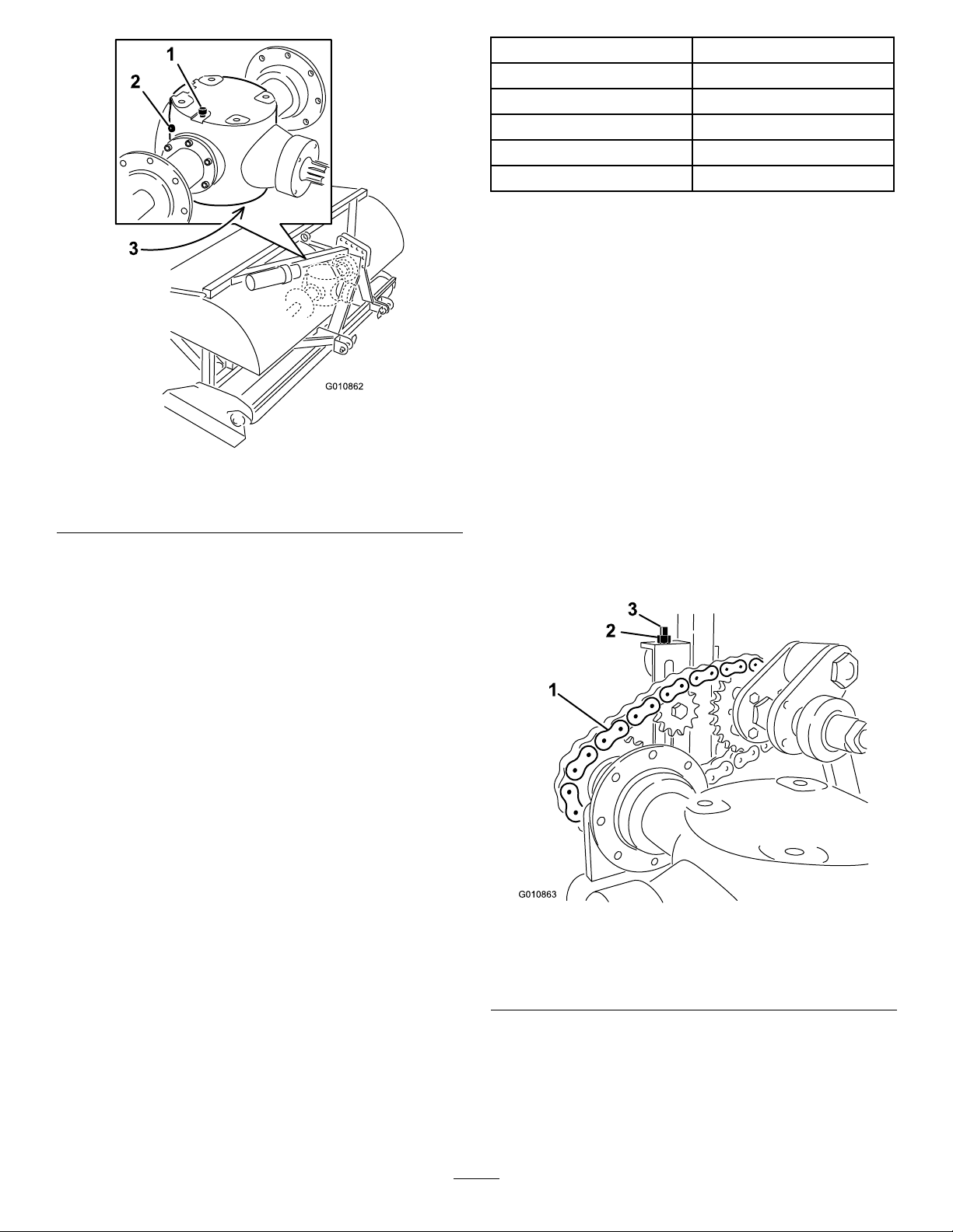
Figure32
1.Vent/Fillplug
2.Checkplug
3.Drainplug
3.Makesureoilisuptothebottomofthecheckplug
holeingearbox(Figure32).
4.Ifoillevelislow ,removevent/llplugfromtopof
gearboxandreplenishoilasrequired.
Model
SR542quarts(1.9liters)
SR54–S2quarts(1.9liters)
SR702quarts(1.9liters)
SR70–S2quarts(1.9liters)
SR724quarts(3.8liters)
GearCaseCapacity
6.Installthevent/llplug.
7.Checktheoillevelandreplenishasrequired.
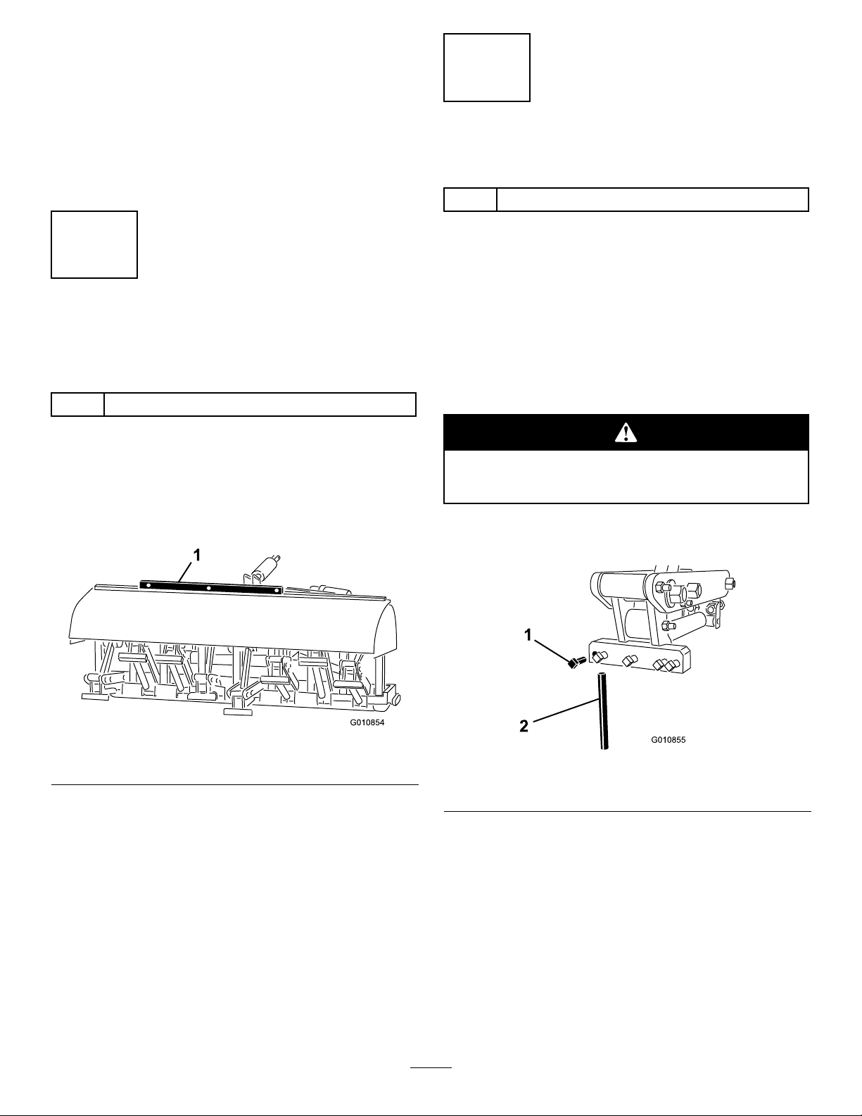
Inspecting/AdjustingtheDrive
Chain
ServiceInterval:Beforeeachuseordaily
Every50hours
Checkthedrivechainfordamageandcorrect
adjustment.Thechainshouldhaveapproximately1/2
inch(12.7mm)ofoveralldeection(1/4inch[6mm]in
eachdirection).
Chaintensioncanbeadjustedbyslightlylooseningthe
mainjamnutandtighteningthejamrodtodesired
position(Figure33orFigure34).Donotadjustthe
chaintensionwhenthechainishotorwarm.
5.Installplugs.
ChangingtheGearboxOil
ServiceInterval:Aftertherst50hours
Every500hours
Thegearboxislledwith80W–90gearoilorequivalent.
1.Cleandebrisfromvent/llpluganddrainplugto
avoidcontamination(Figure32).
2.Removethevent/llplugtorelieveairdraw.
3.Positionadrainpanunderthedrainplugandremove
theplug.
Note:Thehighviscosityofcooloilwillextendthe
draintime.(approximately30minutes)
4.Aftertheoiliscompletelydrained,reinstallthedrain
plug.
5.Fillthegearboxwithhighquality80W-90gearlube.
Usethefollowingcharttodeterminethegearbox
oilcapacity .
Figure33
Models54,54–S,70,&72
1.Drivechain3.Jamrod
2.Jamnut
26

Figure34
Models72
1.Drivechain3.Jamrod
2.Jamnut
Important:Donotovertightenchains;excess
tighteningofchainscancausegearbox/sprocket
damage.
stoppingthePTO.Turnbackthenutsanadditional
2turns.
Note:Donotallowtheclutchtoslipforan
extendedamountoftime.
3.Iftheclutchcontinuestoslipafterturningbackthe
nuts,tighteneachnutanaddition1/4turnuntilthe
slippingceases.Donotovertightenthenutsasshaft
damagemayoccur.
CheckingtheCoringHead
FastenerTorque
ServiceInterval:Aftertherst8hours
Every50hours
Usingthechartbelow,todeterminethetorqueofthe
crankpinnutsandthehingebolts(Figure36).These
arethetwomostcrucialareasofthemachinewhereloss
oftorquewillcausedamagetothecrankshaftalmost
immediately.
AdjustingthePTOClutch
ServiceInterval:Yearlyorbeforestorage
Frictionclutchesmaybecomehotduringuse.
Do not touch.
theareaaroundtheclutchfreeofammable
materialandavoidprolongedslippingofthe
clutch.
1.Attheendoftheseason,backoffeachoftheclutch
nuts2turns(Figure35).
Toavoidtheriskofre,keep
ModelsSR54,
SR54–S,SR70
&SR72–S
CrankShaftNut950ft-lbs.1200ft-lbs.
CrankPinNut950ft-lbs.950ft-lbs.
HingeBolt
1.Crankshaftnut
2.Crankpinnut
265ft-lbs.300ft-lbs.
Figure36
3.Hingebolts
SR72
Figure35
1.Clutchnut2.Clutch
2.Atthestartofthenewseason,startthePTOand
allowtheclutchtoslipforafewsecondsbefore
27

CheckingtheSprings
ServiceInterval:Beforeeachuseordaily
hosesandtheconnectinglinkfromthetractor.Cap
thehydraulichoses.Storethesecomponentswith
theaerator.
Checkthespringsforcrossedorbrokenwires
(Figure37).Crossedorbrokenspringwireswillcause
anerraticholepatternintheturf.
Figure37
1.Correctspringwires2.Crossedspringwires
Note:Replacementwiresareincludedwiththeaerator.
Thewiresareconsideredaconsumableitem.
AdjustingtheHoleSpacing
10.DisconnectthesafetyshieldchainsfromPTOshaft.
11.Pullbackonthelockcollartodisconnectthepower
shaftfromthetractorPTOshaft.
12.SlidethePTOshaftbackandremovefromtractor.
13.ConnectthePTOsafetychaintotheaeratorto
preventthePTOshaftfromcontactingtheground.
14.Removethepinssecuringthelowerlinkarmstothe
aeratorbrackets.Retainpinswithaerator.
Theforwardholespacingisdeterminedbythetractor’ s
gearratio(orthehydrostatictractionpedal).Changing
theengineRPMdoesnotchangetheforwardhole
spacing.
Thelateralholespacingisdeterminedbythenumber
oftinesinthetineheads.
RemovingtheAeratorfrom
theTractor
1.Stoptheaeratoronalevelsurface,notonaslope.
2.DisengagethePTOandengagetheparkingbrake.
3.Raisetheaeratorroller(s)3-6inchesoffground.
Placesupportblocksundertheroller(s).
4.Stoptheengineandremovethekeyfromignition
switch.
5.BeforeleavingtheOperator’sseatontractor,wait
forengineandallmovingpartstostop.
6.Removethetines.
7.Installthestoragestand.
8.Slowlyloweraeratoruntilstoragestandscontact
ground.
9.Removethepinsecuringthetoplinktotheaerator
bracket.Retainpinwithaerator.Also,onmodels
withahydraulictoplink,disconnectthehydraulic
28

TroubleShooting
Problem
Springsarebreakingornotpullingbackthe
headtonormalposition.
Holesareelongatedorpicking.
Tinesarehittingthegroundwithanerratic
pattern.
PTOclutchslipsexcessively.Adjusttinestoshallowdepth.ReplacePTOclutches.Reviewclutchadjustment
Turfispullingupwithcoringtines.Shallow-rootedturfmayrequiresolidtinesthersttime.
Thesoilistoohardforfullpenetration.
Coringtinesarebreaking.Youaretryingtogettoomuchdepthforthesoilcondition.Seeaboveandaerateto
Tineswillnotstayinthehead.
Tinespullthesoilupwhenthemachineis
raised.
Themachinewillnotturn.
Thetractorhasdifcultyliftingtheaerator.Movetractorliftarms3”(76.19mm)to4”(101.6mm)closertotheaerator.Make
Thehydraulictoplinkcylinderisspongy.(It
“gives”andmovesinandoutashortspan
whenforceisapplied.
Machineisnoisyorknocking.
Thehydraulictoplinkcylindercannotbefully
retracted(PTOshaftjams).
Thetractorisdifculttosteerwhenintransport.•Addweighttothefrontofthetractor.
SlowthePTOspeedofthetractor.Thelongerandheavierthetines,thegreaterthe
centrifugalforceonthehead.Checkforcrossedorbrokenspringwires.
Adjusttheangleofthetineorchangethetractorgroundspeed.Makesurethatthe
aeratorcanbeloweredatleast2inchesbelowatgroundleveltoallowforundulation.
•Checkforcrossedorbrokenspringwires.
•SlowthePTOspeedofthetractor.
procedure.
Aerateatadepththatthemachinecanachieve,waterovernight,andthenincrease
thedepth.Repeatifnecessaryuntilsoilcanbeaeratedatdesireddepth.
ashallowerdepth.
Tightenthetineholderbolts;donotusejamnutsorimpactwrench.Iftheboltwillnot
holdthetine,replaceit.
RaisethemachinepartofthewayoutofthesoilbeforedisengagingthePTO.
MakesurethePTO,driveshaftanddrivechainsareworkingproperly .
surethetractorhasthecapacitytolifttheaerator.
Airisinthecylinderorlinesandmustbebledout.
•Crankpinnuthasvibratedloose.•Chainsaretooloose.
•Boltsonthebottomoftheframeattherearofthemainarmhavevibratedloose.
•Checkoillevelingearbox.
ThePTOshaftistoolongforyourtractorandshouldbecuttothecorrectlength.
•Checktirepressureandadjustasrequired.
Solution
29

Storage
Attheendofanaeratingseasonorwhentheaeratorwill
notbeusedforalongperiod,itisgoodpracticetocarry
outthefollowingpreventativemaintenance.
1.Cleanoffanydirtorgreasethatmayhave
accumulatedontheaeratororanyofthemoving
parts.
2.Removeandcleanouttines.Coattineswithoilto
preventrustingduringstorage.
3.Openthehoodandcleanouttheinsideofthe
machine.
4.Lubricateallgreasettingsandtinefastenerscrew
threads.
5.Storethemachineontheprovidedstoragestandson
ahard,drysurface.
6.LoosenthePTOclutchboltstwoturns.
7.ConnectthePTOsafetychaintotheaeratorinstored
positiontopreventdamageorremovethePTOand
storeunderthehoodtominimizecorrosion.
8.Painttherollerandtouch-upanyotherscratcheson
thepaintedsurfaces.
9.Replaceanymissingordamageddecals.
10.Storetheaeratorinsideadrysecurebuilding.Inside
storagewillreducemaintenance,givealonger
workinglifeandincreasetheresidualvalueofthe
machine.Ifinsidestorageisnotavailable,coverwith
aheavysheetortarpaulinandsecuretightly .
30

Notes:
31

Toro Commercial Aerator Products Warranty
A Two-Year Limited Warranty
Conditions and Products Covered
The Toro Company and its affi liate, Toro Warranty Company,
pursuant to an agreement between them, jointly warrant your Toro
Hydroject or ProCore Aerator (“Product”) to be free from defects in
materials or workmanship for two years or 500 operational hours*,
whichever occurs fi rst. Where a warrantable condition exists, we
will repair the Product at no cost to you including diagnosis, labor,
parts, and transportation. This warranty begins on the date the
Product is delivered to the original retail purchaser.
* Product equipped with hour meter
Instructions for Obtaining Warranty Service
You are responsible for notifying the Commercial Products Distributor or Authorized Commercial Poducts Dealer from whom
you purchased the Product as soon as you believe a warrantable
condition exists. If you need help locating a Commercial Products
Distributor or Authorized Dealer, or if you have questions regarding your warranty rights or responsibilities, you may contact us at:
Toro Commercial Products Service Department
Toro Warranty Company
8111 Lyndale Avenue South
Bloomington, MN 55420-1196
952-888-8801
E-mail: commercial.warranty@toro.com
Owner Responsibilities
As the Product owner, you are responsible for required maintenance and adjustments stated in your Operator’s Manual.
Failure to perform required maintenance and adjustments can be
grounds for disallowing a warranty claim.
Items and Conditions Not Covered
Not all product failures or malfunctions that occur during the
warranty period are defects in materials or workmanship. This
warranty does not cover the following:
Product failures which result from the use of non-Toro
•
replacement parts, or from installation and use of add-on,
or modifi ed non-Toro branded accessories and products. A
seperate warranty may be provided by the manufacturer of
these items.
Product failures which result from failure to perform recom-
•
mended maintenance and/or adjustments. Failure to properly
maintain your Toro product per the Recommended Maintenance listed in the Operator’s Manual can result in claims for
warranty being denied.
Product failures which result from operating the Product in an
•
abusive, negligent or reckless manner.
Parts subject to consumption through use unless found to
•
be defective. Examples of parts which are consumed, or
used up, during normal Product operation include, but are
not limited to, brake pads and linings, clutch linings, blades,
reels, rollers and bearings (sealed or greasable), bedknives,
aerator crankshaft and stomper arm bearings, tines, spark
plugs, castor wheels and bearings, tires, fi lters, belts, and
certain sprayer components such as diaphragms, nozzles,
and check valves, etc.
Failures caused by outside infl uence. Items considered to
•
be outside infl uence include, but are not limited to, weather,
storage practices, contamination, use of unapproved coolants,
lubricants, additives, fertilizers, water, or chemicals, etc.
Normal noise, vibration, wear and tear, and deterioration.
•
Normal “wear and tear” includes, but is not limited to, dam-
•
age to seats due to wear or abrasion, worn painted surfaces,
scratched decals or windows, etc.
Parts
Parts scheduled for replacement as required maintenance are warranted for the period of time up to the scheduled replacement time
for that part. Parts replaced under this warranty are covered for the
duration of the original product warranty and become the property
of Toro. Toro will make the fi nal decision whether to repair any ex-
isting part or assembly or replace it. Toro may use remanufactured
parts for warranty repairs.
Maintenance is at Owner’s Expense
Engine tune-up, lubrication cleaning and polishing, replacement of
fi lters, coolant, and completing Recommended Maintenance are
some of the normal services Toro products require that are at the
owner’s expense.
General Conditions
Repair by an Authorized Toro Distributor or Dealer is your sole
remedy under this warranty.
Neither The Toro Company nor Toro Warranty Company is
liable for indirect, incidental or consequential damages in
connection with the use of the Toro Products covered by this
warranty, including any cost or expense of providing substitute equipment or service during reasonable periods of
malfunction or non-use pending completion of repairs under
this warranty. Except for the Emissions warranty referenced
below, if applicable, there is no other express warranty. All
implied warranties of merchantability and fi tness for use are
limited to the duration of this express warranty.
Some states do not allow exclusions of incidental or consequential
damages, or limitations on how long an implied warranty lasts, so
the above exclusions and limitations may not apply to you. This
warranty gives you specifi c legal rights, and you may also have
other rights which vary from state to state.
Note regarding engine warranty:
The Emissions Control System on your Product may be covered
by a separate warranty meeting requirements established by the
U.S. Environmental Protection Agency (EPA) and/or the California
Air Resources Board (CARB). The hour limitations set forth above
do not apply to the Emissions Control System Warranty. Refer to
the Engine Emission Control Warranty Statement printed in your
Operator’s Manual or contained in the engine manufacturer’s
documentation for details.
Countries Other than the United States or Canada
Customers who have purchased Toro products exported from the United States or Canada should contact their Toro Distributor (Dealer)
to obtain guarantee policies for your country, province, or state. If for any reason you are dissatisfi ed with your Distributor’s service or
have diffi culty obtaining guarantee information, contact the Toro importer.
Part Number 374-0032 Rev. C
 Loading...