

Page 1
FormNo.3360-899RevB
HydroJect
ModelNo.09802—SerialNo.280000001andUp
®
3010Aerator
ToregisteryourproductordownloadanOperator'sManualorPartsCatalogatnocharge,gotowww.T oro.com.OriginalInstructions(EN)
Page 2

Introduction
Important:Theengineinthisproductisnot
equippedwithasparkarrestermufer.Itisa
violationofCaliforniaPublicResourceCode
Section4442touseoroperatethisengineonany
forest-covered,brush-covered,orgrass-covered
landasdenedinCPRC4126.Otherstatesor
federalareasmayhavesimilarlaws.
Readthisinformationcarefullytolearnhowtooperate
andmaintainyourproductproperlyandtoavoidinjury
andproductdamage.Youareresponsibleforoperating
theproductproperlyandsafely.
YoumaycontactTorodirectlyatwww .T oro.comfor
productandaccessoryinformation,helpndinga
dealer,ortoregisteryourproduct.
Thismanualidentiespotentialhazardsandhas
safetymessagesidentiedbythesafetyalertsymbol
(Figure1),whichsignalsahazardthatmaycauseserious
injuryordeathifyoudonotfollowtherecommended
precautions.
Figure1
1.Safetyalertsymbol
Thismanualuses2otherwordstohighlightinformation.
Importantcallsattentiontospecialmechanical
informationandNoteemphasizesgeneralinformation
worthyofspecialattention.
Warning
Wheneveryouneedservice,genuineToroparts,or
additionalinformation,contactanAuthorizedService
DealerorToroCustomerServiceandhavethemodel
andserialnumbersofyourproductready.Themodel
andserialnumbersareonaplateontheproduct.Write
thenumbersinthespaceprovided.
ModelNo.
SerialNo.
CALIFORNIA
Proposition65Warning
Theengineexhaustfromthisproduct
containschemicalsknowntotheStateof
Californiatocausecancer,birthdefects,
orotherreproductiveharm.
ThissparkignitionsystemcomplieswithCanadian
ICES-002.
©2008—TheT oro®Company
8111LyndaleAvenueSouth
Bloomington,MN55420
Contactusatwww.T oro.com.
2
PrintedintheUSA.
AllRightsReserved
Page 3

Contents
Introduction.................................................................2
Safety...........................................................................4
SafeOperatingPractices.......................................4
SafetyandInstructionalDecals.............................6
Setup............................................................................9
1InstallingtheRearWheels..................................9
2ActivatingandChargingtheBattery....................9
3CheckingtheTirePressure...............................11
ProductOverview......................................................12
Controls.............................................................12
Specications.....................................................13
Attachments/Accessories...................................13
DepthsandNozzleCongurations.....................14
..........................................................................14
Operation...................................................................15
ThinkSafetyFirst...............................................15
CheckingtheEngineOil.....................................15
FillingtheGasTank...........................................15
CheckingtheGearCaseFluidLevel....................16
CheckingthePumpCaseOilLevel......................17
WaterSystemAccumulator.................................18
OperatingPrecautions........................................18
StartingandStoppingtheEngine........................18
TrainingPeriod...................................................18
WaterSupply......................................................19
OperatingProcedure..........................................19
CheckingtheInterlockSystem............................20
TransportOperation..........................................21
InspectionandClean-UpAfterUse.....................21
PushingorTowingtheMachine..........................21
Maintenance...............................................................23
RecommendedMaintenanceSchedule(s)................23
WaterSystemAccumulator.................................23
DailyMaintenanceChecklist...............................24
LubricatingtheMachine.....................................25
ServicingthePre-Filter.......................................26
ReplacingtheMainWaterFilter..........................26
ChangingtheEngineOilandFilter.....................27
GeneralAirCleanerMaintenance.......................27
ServicingtheAirCleaner....................................27
CheckingandReplacingtheSparkPlugs..............28
ChangingtheGearCaseOilandFilter.................29
ChangingthePumpCaseOil..............................30
CheckingtheHydraulicLinesandHoses.............30
AdjustingtheTractionPumpBelt.......................30
AdjustingtheTransmissionforNeutral...............31
AdjustingtheAerationSpeed..............................32
AdjustingtheParkingBrake................................32
AdjustingtheRollerSprayWashSystem..............33
ServicingtheSprayWashNozzlesor
Strainers.........................................................33
CaringfortheBattery.........................................33
Storage.......................................................................34
PreparingtheWaterSystem................................34
PreparingtheEngine..........................................34
PreparingtheTractionUnit................................34
Troubleshooting.........................................................35
Schematics.................................................................38
3
Page 4

Safety
Improperuseormaintenancebytheoperatoror
ownercanresultininjury.Toreducethepotential
forinjury,complywiththesesafetyinstructions
andalwayspayattentiontothesafetyalert
symbol,whichmeansCAUTION,WARNING,or
DANGER-"personalsafetyinstruction."Failureto
complywiththeinstructionmayresultinpersonal
injuryordeath.
SafeOperatingPractices
–Neverrefuelordraintheaeratorindoors.
•Checkthattheoperatorpresencecontrols,safety
switchesandshieldsareattachedandfunctioning
properly.Donotoperateunlesstheyarefunctioning
properly.
Operation
•Onlyoperateingoodlight,keepingawayfromholes
andhiddenhazards.
•Besurealldrivesareinneutralandparkingbrakeis
engagedbeforestartingengine.Starttheengineonly
fromtheoperatorsposition.
ThefollowinginstructionsarefromANSIstandard
B71.4-2004.
Training
•ReadtheOperator’sManualandothertraining
material.Iftheoperator(s)ormechanic(s)cannot
readEnglishitistheowner’sresponsibilitytoexplain
thismaterialtothem.
•Becomefamiliarwiththesafeoperationofthe
equipment,operatorcontrols,andsafetysigns.
•Alloperatorsandmechanicsshouldbetrained.The
ownerisresponsiblefortrainingtheusers.
•Neverletchildrenoruntrainedpeopleoperateor
servicetheequipment.Localregulationsmayrestrict
theageoftheoperator.
•Theowner/usercanpreventandisresponsiblefor
accidentsorinjuriesoccurringtohimselforherself,
otherpeopleorproperty.
Preparation
•Evaluatetheterraintodeterminewhataccessories
andattachmentsareneededtoproperlyand
safelyperformthejob.Onlyuseaccessoriesand
attachmentsapprovedbythemanufacturer.
•Wearappropriateclothingincludinghardhat,safety
glassesandhearingprotection.Longhair,loose
clothingorjewelrymaygettangledinmovingparts.
•Inspecttheareawheretheequipmentistobeused
andremoveallobjectssuchasrocks,toysandwire
whichcanbecontactedbytheaerator.
•Useextracarewhenhandlinggasolineandother
fuels.Theyareammableandvaporsareexplosive.
–Useonlyanapprovedcontainer.
•Neveroperatewithouttheshields,coversorother
guardssecurelyinplace.Besureallinterlocksare
functioningproperly .
•Keephandsandfeetawayfromthenozzleand
rollerarea.Highvelocitywaterjetscanpenetrate
handsandfeet.Penetrationbythehighvelocity
waterjetscancauseseriouspersonalinjury.If
accidentalpenetrationoccurs,seekmedicalattention
immediately.
•Neverusechemicalsinthewatersupplysystem.
•Donotoperatethewaterinjectionsystem
onconcreteorasphaltbecausewaterjetswill
permanentlydamagethesesurfaces.
•Beforedisconnectingorperforminganyworkon
thewatersystem,allpressureinthesystemmust
berelievedbystoppingtheengineandopeningthe
bleedvalve.Openingthebleedvalveallowsany
trappedwatertoescapefromthesystemandalso
allowstheaccumulatorpistontomovetothebottom
oftheaccumulatorcylinder.
•Donotchangetheenginegovernorsettingor
overspeedtheengine.
•Theaccumulatorinthismachinecontainshigh
pressuredrynitrogen.Accumulatorservicing
requiresspecialtoolsandprecautions.Accumulators
donotcontainuserserviceablecomponents.
Improperaccumulatorservicingcancause
dismembermentordeath.Donotattemptto
disassembleanaccumulator;havethisworkdoneby
anAuthorizedToroDistributor.
•Stoponlevelground,disengagedrives,engage
parkingbrake,shutoffenginebeforeleavingthe
operator’spositionforanyreason.
•Nevercarrypassengersandkeeppetsandbystanders
away.
–Neverremovegascaporaddfuelwithengine
running.Allowenginetocoolbeforerefueling.
Donotsmoke.
•Bealert,slowdownandusecautionwhenmaking
turns.Lookbehindandtothesidebeforechanging
directions.
4
Page 5

•Slowdownandusecautionwhencrossingroads
andsidewalks.
•Donotoperatetheaeratorundertheinuenceof
alcoholordrugs.
•Useextremecarewhenloadingorunloadingthe
aeratorintoatrailerortruck.
•Usecarewhenapproachingblindcorners,shrubs,
trees,orotherobjectsthatmayobscurevision.
•Alwaysbeawareofobstaclesthatmaybeinthe
areaofoperation.Planyouraerationpathtoavoid
contactwithanyobstaclebyyouorthemachine.
SlopeOperation
•Donotoperateneardrop-offs,ditches,steepbanks
orwater.Wheelsorrollersdroppingoveredgescan
causerollovers,whichmayresultinseriousinjury
ordeath.
•Donotoperateonslopeswhengrassiswet.Slippery
conditionsreducetractionandcouldcausesliding
andlossofcontrol.
•Makesureallhydrauliclineconnectorsaretightand
allhydraulichosesandlinesareingoodcondition
beforeapplyingpressuretothesystem.
•Keepyourbodyandhandsawayfrompinhole
leaksornozzlesthatejecthydraulicuidunder
highpressure.Usepaperorcardboard,notyour
hands,tosearchforleaks.Hydraulicuidescaping
underpressurecanhavesufcientforcetopenetrate
theskinandcauseseriousinjury.Seekimmediate
medicalattentionifuidisinjectedintoskin.
•Beforedisconnectingorperforminganyworkon
thewatersystem,allpressureinthesystemmust
berelievedbystoppingtheengineandopeningthe
bleedvalve.Openingthebleedvalveallowsany
trappedwatertoescapefromthesystemandalso
allowstheaccumulatorpistontomovetothebottom
oftheaccumulatorcylinder.
•Letenginecoolbeforestoringanddonotstorenear
ame.
•Shutofffuelwhilestoringortransportingontrailers.
Donotstorefuelnearamesordrainindoors.
•Donotmakesuddenturnsorrapidspeedchanges.
•Reducespeedanduseextremecautiononslopes.
•Removeormarkobstaclessuchasrocks,treelimbs,
etc.fromtheoperatingarea.Tallgrasscanhide
obstacles.
•Watchforditches,holes,rocks,dips,andrisesthat
changetheoperatingangle,asroughterraincould
overturntheaerator.
•Beawarethatlossoftractionmayoccurgoing
downhill.Weighttransfermaycausedrivewheelto
slipandcauselossofbrakingandsteering.
•Beawarethatlossoftractionmayoccurgoing
downhill.Weighttransfermaycausedrivewheelto
slipandcauselossofbrakingandsteering.
•Alwaysavoidsuddenstartingorstoppingonaslope.
Iftirelosestraction,disengagethewaterinjection
systemandproceedslowlyofftheslope.
MaintenanceandStorage
•Parkmachineonlevel,hardground.Neverallow
untrainedpersonneltoservicemachine.
•Usejackstandsorsafetylatchestosupport
componentswhenrequired.
•Carefullyreleasepressurefromcomponentswith
storedenergy.
•Disconnectbatteryorremovesparkplugwirebefore
makinganyrepairs.Disconnectthenegativeterminal
rstandthepositivelast.Reconnectpositiverst
andnegativelast.
•Keephandsandfeetawayfrommovingparts.If
possible,donotmakeadjustmentswiththeengine
running.
•Chargebatteriesinanopenwellventilatedarea,
awayfromsparkandames.Unplugchargerbefore
connectingordisconnectingfrombattery.W ear
protectiveclothinganduseinsulatedtools.
•Keepallpartsingoodworkingconditionandall
hardwaretightened.Replaceallwornordamaged
decals.
Engineexhaustcontainscarbonmonoxide,
whichisanodorless,deadlypoisonthatcan
killyou.
Donotrunengineindoorsorinanenclosed
area.
•UseonlyToro-approvedattachments.W arrantymay
bevoidedifusedwithunapprovedattachments.
5
Page 6
SoundPressureLevel
VibrationLevel
ThisunithasanequivalentcontinuousA-weighted
soundpressurelevelattheoperatorearof93dBA,based
onmeasurementsofidenticalmachinesperDirective
98/37/ECandamendments.
SoundPowerLevel
Thisunithasaguaranteedsoundpowerlevelof:
108dBA/1pW ,basedonmeasurementsofidentical
machinesperDirective2000/14/ECandamendments.
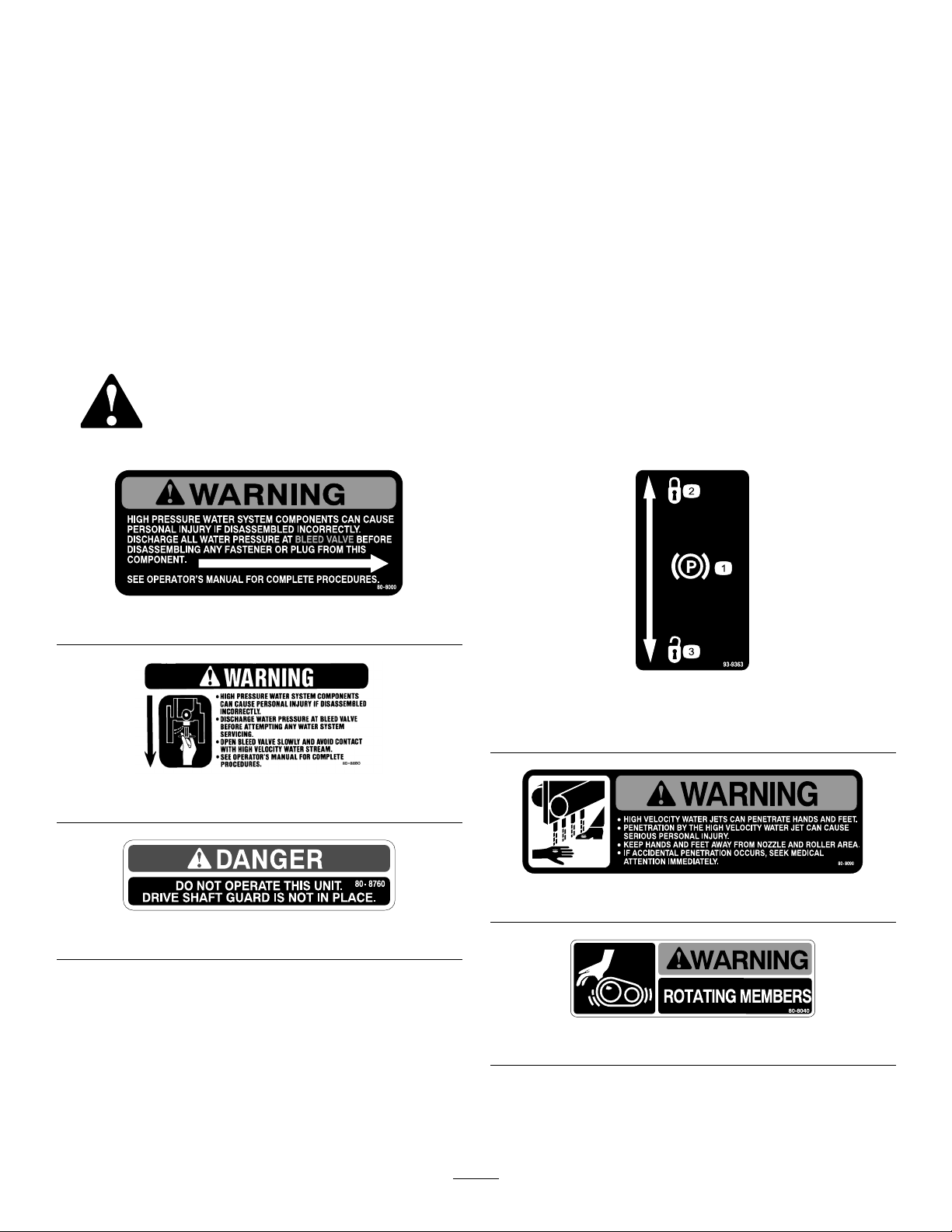
SafetyandInstructionalDecals
Safetydecalsandinstructionsareeasilyvisibletotheoperatorandarelocatednearanyareaof
potentialdanger.Replaceanydecalthatisdamagedorlost.
Thisunitdoesnotexceedavibrationlevelof4.0m/s
thehandsbasedonmeasurementsofidenticalmachines
perISO5349procedures.
2
at
80-8000
93-9363
1.Parkingbrake3.Unlocked
2.Locked
80-8880
80-8090
80-8760
80-8040
6
Page 7
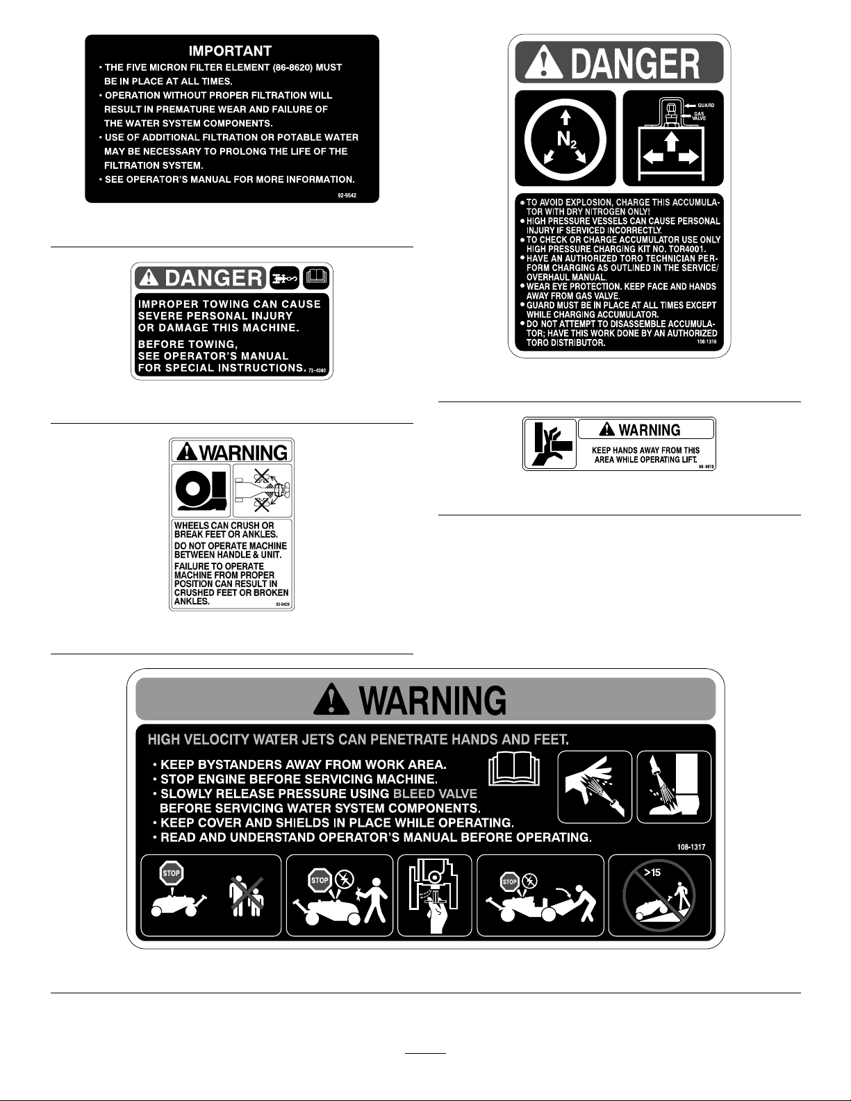
92-9542
108-1316
72-4080
80-8010
93-9429
108-1317
7
Page 8
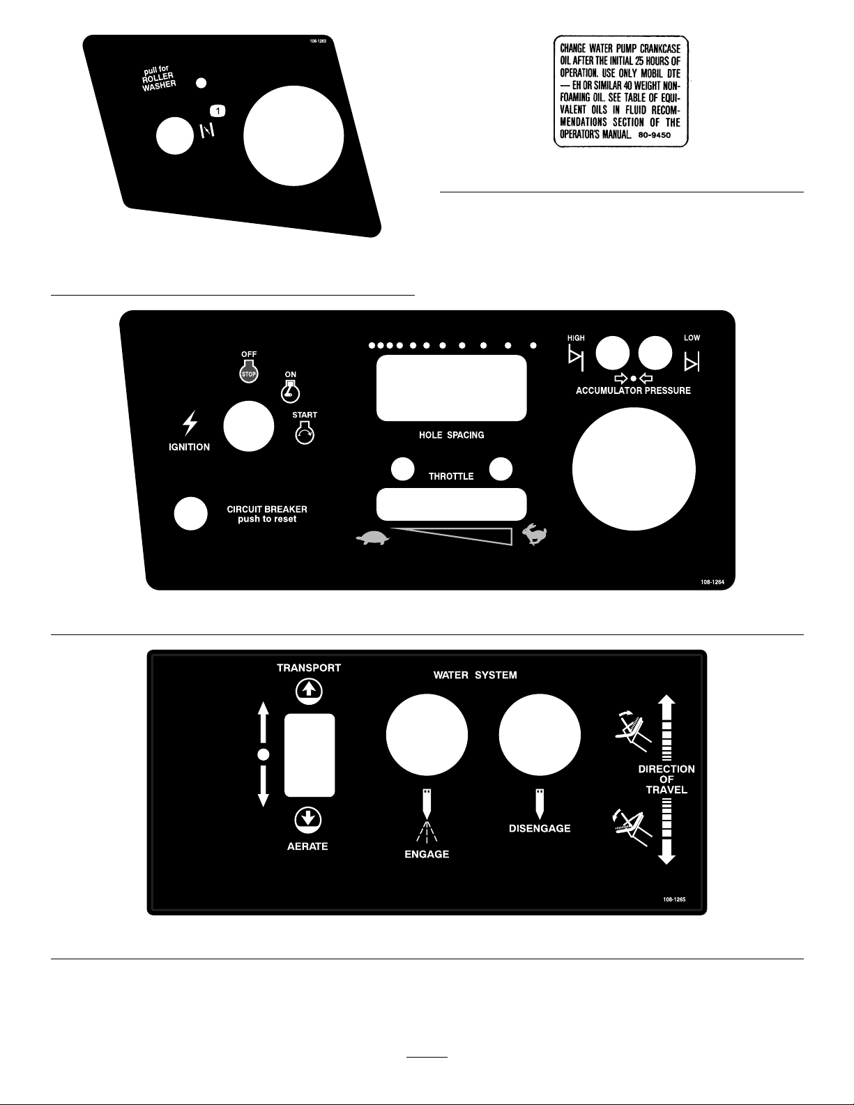
80-9450
108-1263
1.Choke
108-1264
108-1265
8
Page 9

Setup
LooseParts
Usethechartbelowtoverifythatallpartshavebeenshipped.
ProcedureDescription
Wheel3
1
2
3
Lugnut12
Bulkelectrolyte,notsupplied
Nopartsrequired
MediaandAdditionalParts
Description
IgnitionKey1Useinignitionswitch.
HoseAdapter1
SpannerWrench
Operator’sManual
PartsCatalog
Qty.
Mounttoquickcoupleronsideofmachine.
1
1
1
Useforinstallationandremovalofwaterlter.
Readbeforeoperatingtheaerator
Usetoreferencepartnumbers.
Qty.
A/R
Use
Installtherearwheels
Activateandchargethebattery .
–
Checkthetirepressure.
Use
1
InstallingtheRearWheels
Partsneededforthisprocedure:
3Wheel
12Lugnut
Procedure
1.Removethewheelsfromtheshippingpallet.
2.Mountthewheelstothehubswiththelugnuts
(suppliedinlooseparts)(Figure2)andtorquethe
nutsto45-55ft./lb.(61-75N-m).
Figure2
1.Wheel2.Lugnuts
3.Removeanyshippingblocksorbraces,whichmay
obstructmachineremovalfromthepallet.
9
Page 10
Warning
2
ActivatingandChargingthe
Battery
Partsneededforthisprocedure:
Bulkelectrolyte,notsupplied
A/R
Procedure
Warning
CALIFORNIA
Proposition65Warning
Batteryposts,terminals,andrelated
accessoriescontainleadandleadcompounds,
chemicalsknowntotheStateofCalifornia
tocausecancerandreproductiveharm.
Washhandsafterhandling .
CALIFORNIA
Proposition65Warning
Batteryterminalsormetaltoolscouldshort
againstmetaltractorcomponentscausing
sparks.Sparkscancausethebatterygasses
toexplode,resultinginpersonalinjury.
•Whenremovingorinstallingthebattery,
donotallowthebatteryterminalstotouch
anymetalpartsofthetractor.
•Donotallowmetaltoolstoshort
betweenthebatteryterminalsand
metalpartsofthetractor.
1.Sincethebatteryisnotlledwithelectrolyteor
activated,bulkelectrolytewith1.265specicgravity
mustbepurchasedfromalocalbatterysupplyoutlet
Warning
CALIFORNIA
Proposition65Warning
Batteryelectrolytecontainssulfuricacidwhich
isadeadlypoisonandcausessevereburns.
•Donotdrinkelectrolyteandavoidcontact
withskin,eyesorclothing.Wearsafety
glassestoshieldyoureyesandrubber
glovestoprotectyourhands.
•Fillthebatterywherecleanwaterisalways
availableforushingtheskin.
2.Releasethehoodlatchesandraisethehood.
Important:Donotaddelectrolytewhilethe
batteryisinthemachine.Youcouldspillit,
causingcorrosion.
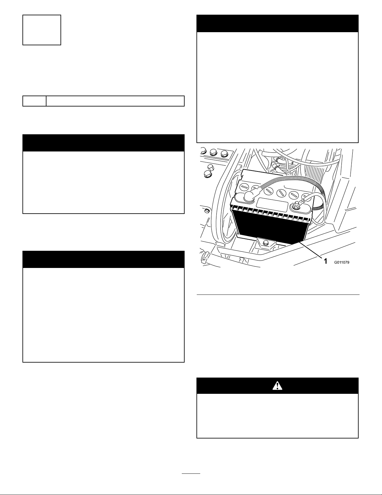
3.Loosenthecapscrewsecuringthebatteryclampto
themachineandremovethebattery(Figure3).
Figure3
1.Battery
4.Cleanthetopofthebatteryandremovethevent
caps.
5.Carefullylleachcellwithelectrolyteuntiltheplates
arecoveredwithabout1/4inch(6mm)ofuid.
6.Allowapproximately20to30minutesforthe
electrolytetosoakintotheplates.Rellasnecessary
tobringtheelectrolytetowithinabout1/4inch(6
mm)ofthebottomofthellwell.
Chargingthebatteryproducesgassesthatcan
explode.
Neversmokenearthebatteryandkeepsparks
andamesawayfrombattery.
7.Connecta3to4ampbatterychargertothebattery
posts.Chargethebatteryatarateof3to4amps
10
Page 11

untilthespecicgravityis1.250orhigherandthe
temperatureisatleast60degreesF(16degreesC)
withallcellsgassingfreely.
8.Whenthebatteryischarged,disconnectthecharger
fromtheelectricaloutletandbatteryposts.
3
CheckingtheTirePressure
Note:Afterthebatteryhasbeenactivated,add
onlydistilledwatertoreplacenormalloss,although
maintenance–freebatteriesshouldnotrequirewater
undernormaloperatingconditions.
9.Installthebatteryandsecureitwiththebattery
clamp.
10.First,installthepositivecable(red)tothepositive
(+)terminalandthenthenegativecable(black)to
thenegative(–)terminalofthebattery.Slidethe
rubberbootoverthepositiveterminaltopreventa
possibleshortfromoccurring.
Warning
CALIFORNIA
Proposition65Warning
Incorrectbatterycableroutingcoulddamage
themachineandcablescausingsparks.Sparks
cancausethebatterygassestoexplode,
resultinginpersonalinjury.
•Alwaysdisconnectthenegative(black)
batterycablebeforedisconnectingthe
positive(red)cable.
NoPartsRequired
Procedure
Thetiresareover–inatedforshipping.Therefore,
releasesomeoftheairtoreducethepressure.Correct
airpressureinfrontandreartiresis8–12psi.
•Alwaysconnectthepositive(red)
batterycablebeforeconnectingthe
negative(black)cable.
Warning
CALIFORNIA
Proposition65Warning
Connectingcablestothewrongpost
coulddamagetheelectricalsystemand
resultinpersonalinjury.
Note:Makesurebatterycablesareroutedaway
fromanysharpedgesormovingparts.
11.Lowerthehoodandsecurethelatches.
11
Page 12
ProductOverview
Controls
HourMeter
Thehourmeter(Figure4)registersaccumulatedhours
ofengineoperation.Usethehourmetertodetermine
intervalsforservicemaintenanceandlubrication.
IgnitionSwitch
Theignitionswitch(Figure4),whichisusedtostart
andstoptheengine,hasthreepositions:OFF ,ON,and
START.
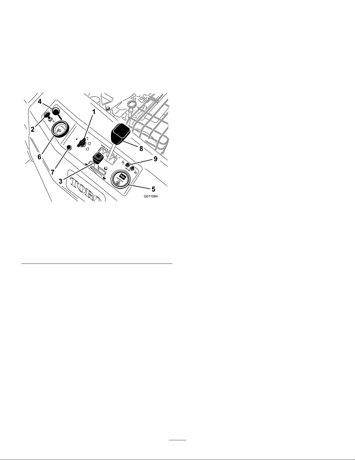
Figure4
1.Ignitionswitch6.Waterpressuregauge
2.Choke7.Circuitbreakerreset
3.Throttle
4.Spraywashcontrol
5.Hourmeter
button
8.Spacingcontrollever
9.Accumulatorpressure
lights
WaterPressureGauge
Thewaterpressuregauge(Figure4)registerssupply
waterpressureinthesystem.Italsoactsasaninterlock
switch,preventingthewaterpumpfromstartingifthe
waterpressureisbelow20-28p.s.i.,orstoppingthewater
pumpifthewaterpressuredropsbelow7-13p.s.i.Check
thegaugefrequentlytomonitorthewaterpressure.
CircuitBreakerResetButton
Pushthebutton(Figure4)toresetthebreakerafter
correctingamalfunctionintheelectricalsystem.The
buttonalsoservesasaswitchtointerruptpowertothe
relays.
SpacingControlLever
Movingthecontrol(Figure4)awayfromthehandle
increasestheaeratinggroundspeedandthedistance
betweenholes.Movingthecontroltowardthehandle
decreasestheaeratinggroundspeedandthedistance
betweenholes.Thesettingwillbeoverriddenwhenthe
machineisshiftedtothetransportposition.
AccumulatorPressureLights
Choke
Tostarttheengine,closethecarburetorchokebypulling
thechokecontrol(Figure4)outwardtotheFULL
position.Aftertheenginestarts,regulatethechoketo
keeptheenginerunningsmoothly.Assoonaspossible,
openthechokebypushingitinwardtotheOFFposition
Throttle
Thethrottle(Figure4)isusedtoregulatetheengine
speed.Movingthethrottleforwardincreasestheengine
speed(FAST);rearwarddecreasestheenginespeed
(SLOW).
SprayWashControl
Pullthehandle(Figure4)upwardtoactivatetheroller
spraywashsystem.Movethecontrolknobupordown
toadjustthesprayratetokeeptherollersfreeofdebris.
Thehighorlowpressurelights(Figure4)willonly
illuminateifahighorlowpressureconditionoccurs
intheaccumulator.Ifalightilluminatesthesystem
willlnotoperateorwillshutdown,ifoperating.Refer
toWaterSystemAccumulatorinformationinthe
Operationsection.
TractionBail
Thetractionbail(Figure5)engagesandregulatesfore
andafttractionoperationofthemachine.Releasingthe
bailstopstractionoperationandwillalsostopwater
injectionin3to4seconds,unlessthebailisre-engaged.
Thetransportspeedisregulatedbytheamountthebail
ismoved.
12
Page 13
Specications
Note:Specicationsanddesignaresubjecttochange
withoutnotice.
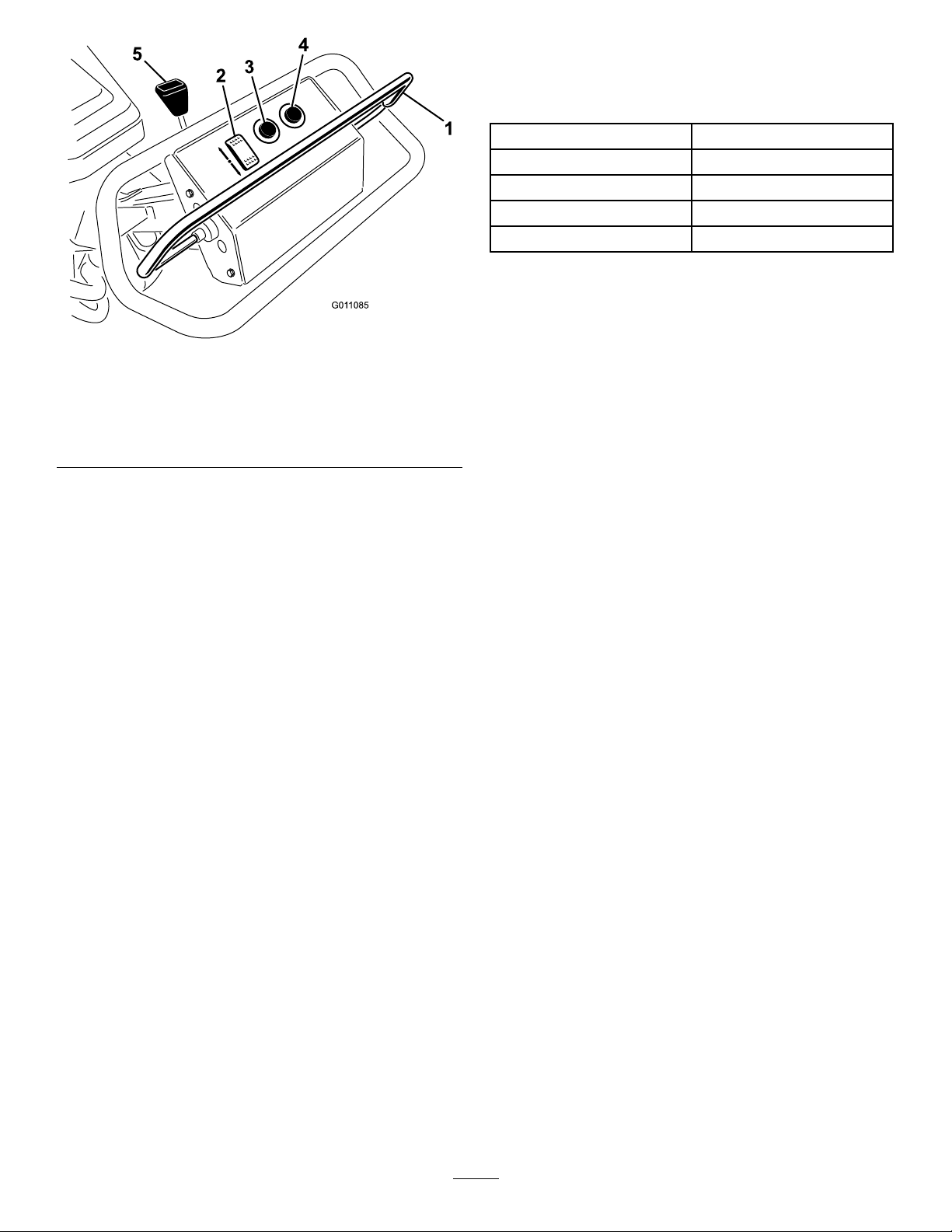
Figure5
1.Tractionbail4.Aerationstopbutton
2.Transport/aeraterocker
switch
3.Aerationengagement
button
5.Parkingbrake
Transport/AerateRockerSwitch
Theswitch(Figure5)lowersmachineontotherollers
tocommenceaeration.Theswitchwilloverridethe
spacingcontrolsettingwhenitismovedtothetransport
position.
Length
Wheelbase
Width
Height
Weight
96.2inches(244cm)
53.2inches(135cm)
63inches(160cm)
38.2inches(97cm
1120lb.(508kg)
Attachments/Accessories
AselectionofToroapprovedattachmentsand
accessoriesareavailableforusewiththemachineto
enhanceandexpanditscapabilities.Contactyour
AuthorizedServiceDealerorDistributororgoto
www.Toro.comforalistofallapprovedattachments
andaccessories.
AerationEngagementButton
Depressingthebutton(Figure5),startsthewater
injectionsystemonlywhenthewaterpressureisabove
28p.s.i.andtherollersareontheground.
AerationStopButton
Theredbutton(Figure5)stopsthewaterinjection
system.Thesystemcontinuesforafewsecondsafter
thebuttonispressed.
ParkingBrake
Pushthelever(Figure5)towardthemachinetoengage
theparkingbrake.Awarningbuzzerwillsoundif
youattempttomovethemachinewithparkingbrake
engaged.
FuelShut-OffValve
Thefuelshut-offvalveislocatedunderthefueltank.
Closethevalvewhenstoringortransporting(trailering)
themachine.
13
Page 14
DepthsandNozzleCongurations
Allnozzlesareidentiedwithnumbersindicatingthedrillsizeoftheorice.Thestandardcongurationis11
nozzlesproducingdepthsof4to6inchesdependingonturfconditions.Blockednozzlelocationsareobtainedby
reversingthenozzlecheckvalveballandspring.Seenozzlesizechartandillustrationsbelow:
Important:Useonlynozzlecongurationsshownordamagetothemachinemayoccur.
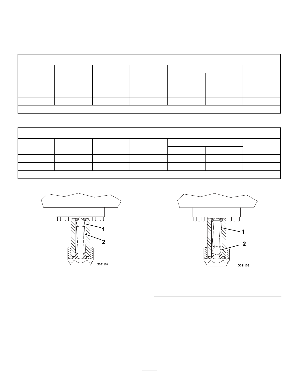
NozzleSizeandApproximateDepthChart
PartNo.
86-8130
86-8131
86-8133
DrillSize
#56
#53
#46
DecimalSize
(inch)
0.04651.181
0.05951.5111104-6inches
0.0812.0576
*Useonlywithvariedsizecongurations
MetricSize
(mm)
QuantityofNozzles
Open
***
Important:AluminumWasher,ToroPartno.80-6680,isrequiredwithanynozzlechange.
OptionalStaggeredSizeNozzleConguration
PartNo.
86-8130
86-8133
DrillSize
#56
#46
**Additionalnozzlesmaybeblockedtocompensateforpumpwear .
DecimalSize
(inch)
0.04651.1816and
0.0812.057
MetricSize
(mm)
QuantityofNozzles
OpenBlocked**
5
Important:AluminumWasher,ToroPartno.80-6680,isrequiredwithanynozzlechange.
Approximate.
Blocked
5
0**
0**
Depth
6-8inches
Approximate.
Depth
3-4inches
6-8inches
Figure6
OpenNozzle
1.Checkvalveball2.Spring
Figure7
Closed(Blocked)Nozzle
1.Spring2.Checkvalveball
14
Page 15

Operation
Note:Determinetheleftandrightsidesofthe
machinefromthenormaloperatingposition.
ThinkSafetyFirst
Pleasecarefullyreadallofthesafetyinstructions
andsymbolsinthesafetysection.Knowingthis
informationcouldhelpyouorbystandersavoidinjury.
Theuseofprotectiveequipment,suchasbutnot
limitedto,foreyes,ears,feet,andheadisrecommended.
Figure8
1.Dipstick
2.Oilllcap
Thismachineproducessoundlevelsinexcess
of85dBAattheoperatorsearandcancause
hearinglossthroughextendedperiodsof
exposure.
Wearhearingprotectionwhenoperatingthis
machine.
CheckingtheEngineOil
ServiceInterval:Beforeeachuseordaily—Checkthe
engineoil.
Theengineisshippedwithoilinthecrankcase;
however,theoillevelmustbecheckedbeforeandafter
theengineisrststarted.
Crankcasecapacityisapproximately2qt(1.4l)with
thelter.
Usehigh-qualityengineoilthatmeetsthefollowing
specications:
APIClassicationLevelRequired:SJ,SK,SLorhigher.
Preferredoil:SAE10W–30(above0degreesF)
Alternateoil:SAE5W–30(below32degreesF)
ToroPremiumEngineoilisavailablefromyour
distributorin10W–30viscosity.Seethepartscatalog
forpartnumbers.
1.Parkthemachineonalevelsurface,stoptheengine
andremovethekeyfromtheignitionswitch.
Note:IftheoillevelisattheADDmarkonthe
dipstick,add1quartofoiltoraisetheoillevelto
FULL.Donotoverll.
3.Removethecapfromtheoilll.Pouroilintothe
oillluntilthelevelisattheFULLmarkonthe
dipstick.
Important:Theaeratoroperatesatvery
highengineloads,sochecktheoillevelevery
8operatinghoursordaily.Anewengine
mayconsumesomeoiluntilitisbrokenin.
Initially,changetheoilaftertherst25hoursof
operation;thereafter,undernormalconditions,
changetheoilandlterafterevery100hours
ofoperation.Changetheoilmorefrequently
whentheengineisoperatedinextremelydusty
ordirtyconditions.
FillingtheGasTank
Werecommendtheuseoffresh,clean,unleadedregular
gradegasoline.Unleadedgasolineburnscleaner,
extendsenginelife,andpromotesgoodstartingby
reducingthebuild-upofcombustionchamberdeposits.
Note:Donotmixoilwiththegasoline.Neveruse
methanol,gasolinecontainingmethanol,gasohol,
gasolineadditives,premiumgasoline,orwhitegas
becauseengineandfuelsystemdamagecouldresult.
2.Removethedipstickfromtheoilllerneck
(Figure8)andwipeitwithacleanrag.Insertthe
dipstickintothellerneckandmakesureitisseated
fully.Pullthedipstickfromthellerneckandcheck
theoillevel.Iftheoillevelislow,addenoughoilto
raisetheleveltotheFULLmarkonthedipstick
15
Page 16

Incertainconditions,gasolineisextremely
ammableandhighlyexplosive.Areor
explosionfromgasolinecanburnyouand
othersandcandamageproperty.
•Fillthefueltankoutdoors,inanopenarea,
whentheengineiscold.Wipeupany
gasolinethatspills.
•Donotllthefueltankcompletelyfull.Add
gasolinetothefueltankuntilthelevelis1
in.(25mm)belowthebottomoftheller
neck.Thisemptyspaceinthetankallows
gasolinetoexpand.
•Neversmokewhenhandlinggasoline,and
stayawayfromanopenameorwhere
gasolinefumesmaybeignitedbyaspark.
•Storegasolineinanapprovedcontainerand
keepitoutofthereachofchildren.Never
buymorethana30-daysupplyofgasoline.
•Alwaysplacegasolinecontainersonthe
groundawayfromyourvehiclebeforelling.
•Donotllgasolinecontainersinsidea
vehicleoronatruckortrailerbedbecause
interiorcarpetsorplastictruckbedliners
mayinsulatethecontainerandslowtheloss
ofanystaticcharge.
•Whenpractical,removegas-powered
equipmentfromthetruckortrailerand
refueltheequipmentwithitswheelsonthe
ground
•Ifthisisnotpossible,thenrefuelsuch
equipmentonatruckortrailerfroma
portablecontainer,ratherthanfroma
gasolinedispensernozzle.
•Ifagasolinedispensernozzlemustbeused,
keepthenozzleincontactwiththerimof
thefueltankorcontaineropeningatall
timesuntilfuelingiscomplete.
1.Removethecapfromthefueltank(Figure9)and
llthe10gallontanktoabout1inch(25mm)from
thetopoftank(thebottomofthellerneck)with
unleadedgasoline.Installthefueltankcaptightly.
Figure9
1.Fueltankcap
2.Wipeupgasolinethatmayhavespilledtopreventa
rehazard.
CheckingtheGearCaseFluid
Level
ServiceInterval:Beforeeachuseordaily
Themachinesreservoirislledatthefactorywith
approximately4-5quartsofhighqualityhydraulic
uid.Checkthelevelofthehydraulicuid,onthe
sightgauge,beforetheengineisrststartedanddaily
thereafter.Therecommendedreplacementuidis:
MobilDTE26
Alternateuids:Ifthisuidisnotavailable,other
uidsmaybeusedprovidedtheymeetallthefollowing
materialpropertiesandindustryspecications.Wedo
notrecommendtheuseofsyntheticuid.Consult
withyourlubricantdistributortoidentifyasatisfactory
product.
Note:Torowillnotassumeresponsibilityfordamage
causedbyimpropersubstitutions,souseonlyproducts
fromreputablemanufacturerswhowillstandbehind
theirrecommendation.
Anti-wearHydraulicFluid,ISOVG68
MaterialProperties:
Viscosity,ASTMD445cSt@40°C65to71
ViscosityIndexASTM
D2270
PourPoint,ASTMD97-18°Fto-30°F
IndustrySpecications:
VickersI-286-S(QualityLevel),VickersM-2950-S
(QualityLevel),DenisonHF-0
cSt@100°C8.4to8.9
97to107
Note:Manyhydraulicuidsarealmostcolorless,
makingitdifculttospotleaks.Areddyeadditive
16
Page 17

forthehydraulicsystemoilisavailablein2/3oz.(20
ml)bottles.Onebottleissufcientfor4-6gal(15-22
1)ofhydraulicoil.Orderpartno.44-2500fromyour
authorizedTorodistributor.
1.Positionthemachineonalevelsurface.
2.Releasethehoodlatchesandraisethehood.
3.Checkthelevelofhydraulicoilonthesightgauge
(Figure10).Theuidlevelshouldbeuptothe
middleofthegaugewindow .
ShellMorlinaSd150
ChevronAWMachineOil150
ConocoMultipurposeR&O0.1150
ExxonTerresstic150
Philllips
SunSunvis150
76Lubricants
CastrolParadene150R&O
MagnusOil150
TurbineOil150
Important:Theoilmustbechangedimmediately
whenanycontamination,sludge,water,or
condensationappearsintheoil.Determineand
correctanyoilcontaminationproblembefore
restartingtheengineandoperatingthemachine.
1.Positionthemachineonalevelsurface.
2.Releasethehoodlatchesandraisethehood.
3.Removethedipstick/llercapandchecktheoil
levelonthedipstick.Theuidlevelshouldbeupto
theFULLmark(Figure11).
Figure10
1.Sightgauge
2.Fillercap
4.Iftheuidlevelislow ,removethellercapand
addenoughhydraulicoiltobringtheoiluptothe
properlevel.
5.Lowerthehoodandsecurethelatches.
Note:Theoilandltermustbechanged
immediatelywhenanycontamination,sludge,water
orcondensationappearsinoiloronsightgauge.
Determineandcorrectoilcontaminationproblem
beforerestartingengineandoperatingmachine.
CheckingthePumpCaseOil
Level
ServiceInterval:Beforeeachuseordaily
Aftertherst25hours
Every200hours
Figure11
1.Dipstick/llercap
2.Full
4.Iftheuidlevelislow ,addenoughMobilDTE
ExtraHeavyoilorequivalentoiltobringtheoilup
totheproperlevel.Donotoverll.
5.Lowerthehoodandsecurethelatches.
Thepumpcrankcaseislledatthefactorywith
approximately40ouncesofMobilDTEExtraHeavy
oil.Checktheoillevelonthedipstickbeforetheengine
isrststartedanddailythereafter.Changetheoil
initiallyafter25hoursofoperation,thereafterchange
every200hoursofoperation.Seethefollowingchart
forequivalentoils.
17
Page 18

WaterSystemAccumulator
TheHydrojectaccumulatorcontainsahighpressure
nitrogengaspre-charge.Thesafetysystemonthe
aeratorwilldisablethewaterinjectioniftheaccumulator
pressureistoolowortoohigh,andwillilluminateone
oftheaccumulatorpressurelightsontheoperators
console.
Duetotheoperationalrequirementsoftheaccumulator
design,thehighpressureinternalgaspre-chargecan
bleedoutduringperiodsofinactivity.Storingthe
Hydrojectforextendedperiodsoftime(3monthsor
longer)and/orseasonaltemperaturevariancescan
affecttheaccumulatorsabilitytoretainasufcient
pre-chargeandseasonalservicing(recharge)maybe
required.
Ifoneoftheaccumulatorchargeindicatorlamps
illuminates,contactyourauthorizedT oroDistributor
foraccumulatormaintenanceservices.
•Useagood,clean,qualitywatersupplyinthe
system.Ifgoodqualitywaterisnotavailable,
additionalltrationequipmentmayberequired.Do
notusechemicalsinthewatersystem.
•Donotallowthemachinetobesubjecttofreezing
temperatureswithoutdraining,asdamagetothe
systemwilloccur.
StartingandStoppingthe
Engine
1.Makesurethatthewiresareinstalledonthespark
plugsandthefuelshut-offvalveisopen.
2.Makesurethattheparkingbrakeisengaged.
3.PullthechokeleverouttotheFULLpositionand
movethethrottlelevertothehalfthrottleposition.
Note:Whenstartingawarmengine,thechoke
maynotbenecessary,butHALFthrottleis.
OperatingPrecautions
Followtheseprecautionswhenoperatingtheaerator:
•Beforeaerating,inspecttheworkareafordebrisand
obstacles.Determinethebestdirectionandpattern
tooperatethemachine.Alwaysmaintainawareness
ofwhatliesaheadinthedirectionofforwardtravel.
•Ifthemachinestartstovibrateabnormally,shutthe
engineoff.Removethekeyfromtheignitionswitch
topreventthepossibilityofaccidentalstarting.
Checkthemachinefordamagedparts.Repairany
damagebeforerestartingtheengineandoperating
themachine.
•Onlyusetheaeratorindaylightorwhenthereis
goodarticiallight.W atchforholesorotherhidden
hazards.Donottransportthemachineclosetoa
sandtrap,ditch,creek,orotherhazard.
•Topreventrollermarks,alwaysraisethemachineto
thetransportpositionwhenparkedonagreen.
•Donotoperatethewaterinjectionsystem
onconcreteorasphaltbecausewaterjetswill
permanentlydamagethesesurfaces.Donotrun
overthehoseasdamagewilloccur.
•Donotoperatetheaeratorwiththerolleror
injectionsystemovertheedgeofanythingthat
couldbehit,damaged,orinjuredbyhighvelocity
waterblasts.
•Waterjetsfromtheinjectionsystemshouldnot
damageirrigationheadsononepassofthemachine.
Donotallowmultipleshotsfromtheinjection
systemtohitirrigationheadsasdamagewilloccur.
4.Insertthekeyintotheignitionswitchandrotateit
clockwisetostarttheengine.Releasethekeywhen
theenginestarts.Graduallyreturnthechokelever
totheOFFposition(leverallthewayin)afterthe
enginestartsandwarmsup.
Important:T opreventoverheatingofthe
startermotor,donotengagethestarterlonger
than30seconds.After30secondsofcontinuous
cranking,wait2minutesbeforeengagingthe
startermotoragain.
Important:Theengineisequippedwithan
oilpressureinterlockswitchwhichinterrupts
theengineoperationifthereisnotsufcient
oilpressureintheengineduringstartingor
operation.Theenginemaystartbutwillnot
continuetorunduetoalackofoilpressure.
5.Tostoptheengine,movethethrottlecontrol
downwardtotheSLOWpositionandturnthe
ignitionkeytoOFF.Removetheignitionkey.
TrainingPeriod
Beforeaeratingwiththemachine,itissuggestedthat
youndaclearareaandpracticestartingandstopping,
raisingandloweringmachine,turning,etc.Thistraining
periodwillbebenecialtotheoperatoringaining
condenceintheperformanceoftheaerator.
18
Page 19

WaterSupply
Recommendedsourcewith7-8gallonsperminute.
Aminimumpressureof30p.s.i.atthemachineis
requiredforthepumptoengage.Maximumallowable
pressureof200psi.Althoughirrigationwaterpumped
frompondsorefuentholdingpoolscanbeused,not
allconditionscanbehandledbytheltrationsystem.
Additionaloralternativeltrationmayberequired.
OperatingProcedure
1.Makesurethatthewiresareinstalledonthespark
plugsandthefuelshut-offvalveisopen.
2.Uncoilagardenhose,makingsurethatthereareno
kinksorbendsinthehose.Layoutthehosesothat
therearenoobstructionsbetweenthemachineand
theareatobeaerated.Turnonthewatersupplyto
purgeanyairfromthehose.Turnoffthewater.
3.Connectthehoseadapter(Figure12)tothegarden
hose,thenconnecttheadaptertothequickcoupler
onthesideofthemachine.
Figure13
1.Mainwaterlterhead
2.Bleedbutton
6.Reachunderthehoodandopenthebleedvalve
onthemainvalveattherearofthemachine
(Figure14).Bleedthesystemuntilasteadyowof
watercomesfromtheoutlet;thenclosethevalve.
Figure12
1.Hoseadapter
2.Quickcoupler
4.Turnonthewatersupplyandcheckthewater
pressure.Thewaterpressuremustbeatleast30
p.s.i..Ifthesystempressureisnot30p.s.i.,make
surethatthehoseisnotkinkedorobstructed,the
watersupplyisturnedon,andthewaterlterisnot
plugged.
Donotoperatetheenginewhilebleedingthe
lterhead.
5.Reachunderthefueltankandpressthebleed
buttonontopofthewaterlterhead(Figure13).
Holdthebleedbuttondownuntilallairispurged
fromthelterandwatercomesoutoftheopening.
Figure14
1.Mainvalve2.Bleedvalve
7.Ifdesired,thevalveonthepre-lter(Figure15)may
beopenedslightly(cracked)toprovidecontinuous
ushingduringoperationofthemachine.
19
Page 20

Figure15
1.Pre-lter
2.Valve
8.Starttheengine;refertoStartingandStoppingthe
Engine.MovethethrottletotheFASTpositionand
disengagetheparkingbrake.
9.Engagethetractionbailandapproachtheareato
beaerated.Makesurethattherearenoobstructions
betweentheaeratorandwatersupply.Always
maintainawarenessofwhatliesaheadinthe
directionofforwardtravel.
10.Engageandholdthetransport/aeratetoggleswitch
tofullylowerthemachineontotherollers.Release
theswitchwhenthemachineisfullylowered;then
presstheengagementbuttontostartwaterinjection.
Note:Theinjectionoperationstartsapproximately
4-5secondsafterthepumpengages.Also,the
injectionsystemwillautomaticallystopifthe
tractionbailisnotengagedwithin3-4secondsafter
startingthewatersystem.
downtoallowmultipleshotswhilemachineis
stopped.
Important:Holedepthscanreach20inches
ormorewhenstationaryormakingmultiple
shots,sobeawareofwhatisburiedbelowthe
turf.Also,anexcessiveamountofholesand
muddyturfconditionsmayoccurwhenmaking
multipleshots.
14.Tostopwaterinjection,presstheredbutton.The
systemcontinuesforafewsecondsafterthebutton
ispressed.Raisethemachinetothetransport
position,disconnectthesupplyhose,andmoveto
thenextlocation.
CheckingtheInterlockSystem
Ifsafetyinterlockswitchesaredisconnected
ordamagedthemachinecouldoperate
unexpectedly,causingpersonalinjury.
•Donottamperwiththeinterlockswitches.
•Checktheoperationoftheinterlock
switchesdailyandreplaceanydamaged
switchesbeforeoperatingthemachine.
Thepurposeofthesafetyinterlocksystemistoprevent
theenginefromcrankingorstartingunlessthetraction
bailisinNEUTRALandpreventsthewatersystem
fromengagingifthemachineisinthetransport(raised)
position.Italsostopsaerationifthetractionbailis
releasedwhileoperatingorifthemachineisraisedto
thetransportposition.
11.Whenaerating,workmovingperpendicularfrom
thewatersupplytoavoidrunningoverthegarden
hose.Usethefrontedgeofthehoodorrearcorner
oftheframetoalignrows,ifdesired.Whenatthe
endofarow,makean“S”maneuverandreversethe
directionoftheaerator.Donotmakesharpturns
onagreenorscufngfromthetiremayoccur.
Alwaysmaintainawarenessofwhatliesaheadinthe
directionofforwardtravel.
12.Regulatetherollerspraywash,ifrequired,to
removedebrisfromtherollers.
Note:Asmallamountofwaterfromtheregulator
bypassmaycomeoutofthespraywashnozzles
evenwiththespraywashintheOFFposition.
13.Inareaswheregreaterholedepthormorefrequent
holesaredesired,theengagebuttoncanbeheld
Todoafunctionalcheckofinterlocksystem:
1.Positionthemachineinaat,openareaonrough
turfandawayfromburiedwires,plumbing,etc.
Stoptheengine.
2.Movethetractionbailupanddownwhiletrying
tostarttheengine.Iftheenginecranks,thereisa
malfunctionintheinterlocksystemthatmustbe
corrected.Iftheenginedoesnotcrank,proceed
tostep3.
3.Connectthewatersupplytothemachine.Turn
onthewatersupplyandbleedallairoutofthe
system.Thewaterpressuremustbe30psiormore.
Starttheengine.Raisethemachinetothetransport
position(upofftherollers).Pushtheaerate
ENGAGEbutton.Ifthewaterpumpengagesand
themachinebeginsaerating,thereisamalfunction
20
Page 21

intheinterlocksystemthatmustbecorrected.Ifthe
machinedoesnotbeginaerating,proceedtostep4.
4.Lowerthemachinetotheaerateposition(on
therollers).Engagethetractionbailtostartthe
machinemoving.Push,thenreleasetheaerate
ENGAGEbutton.Thewaterpumpshould
engageimmediately ,thenthemachineshould
beginaerating5secondsafterthepumpengages.
Releasethetractionbailtotheneutralpositionso
thatthemachinestopsmoving.Thewaterpump
shoulddisengage4secondsafterthetractionbail
returnstoneutral,thenstopaeratingafteranother
3seconds.Ifthemachinedoesnotstopaerating
whenthetractionbailreturnstoneutral,thereisa
malfunctionintheinterlocksystemthatmustbe
corrected.Ifthemachinestopsaerating,proceed
tostep5.
5.Engagethetractionbailtostartthemachine
moving,thenpushtheaerateENGAGEbutton
tobeginaerating.PushtheaerateDISENGAGE
button.Thewaterpumpshoulddisengage
immediately,thenstopaeratingafter3seconds.
Ifthemachinedoesnotstopaerating,thereisa
malfunctionintheinterlocksystemthatmustbe
corrected.
Lights(LED’s)onthecontroller(Figure16)
indicatewhenthefollowinginputsaremadetothe
controller:
Red
GreenAeratestart(engage)switchclosed.Ifthered
Yellow
Transportswitchclosed(tractionbailinneutral)
andyellowlightsareon,thegreenlightwillstay
onuntileithertheredoryellowgoesoff.
Pumpstartlimitswitchclosed(machinelowered
toaerateposition)andwaterpressureswitch
closed(waterpressureofmorethan30psi)and
accumulatorchargepressureswitch(nitrogen
pressuremorethan1800psi).
TransportOperation
Usethetractionbailtoslowthemachinewhilecrossing
undulatingterraintoavoidlossofcontrol.Thesmooth
tiresdonotgripturfverywellsousecautionwhen
transportingthemachine.Alwaysapproachrough
areasatareducedspeedandcrosssevereundulations
carefully.
InspectionandClean-UpAfter
Use
Atthecompletionofoperation,thoroughlywash
themachinewithagardenhosewithoutanozzleso
excessivewaterpressurewillnotcausecontamination
anddamagetosealsandbearings.Aftercleaning,itis
recommendedthemachinebeinspectedforpossible
hydraulicuidorwaterleaksanddamageorwearto
hydraulic,water,andmechanicalcomponents.
PushingorTowingthe
Machine
Inanemergency,themachinecanbepushedor
towedforaveryshortdistance.However,wedonot
recommendthisasstandardprocedure.
Important:Donotpushorthetowmachinefaster
than3MPHbecausepumpdamagemayoccur.
Ifthemachinemustbemovedaconsiderable
distance,transportitonatruckortrailerorpull
itwiththetractionwheelraisedandsecuredtoa
dolly(OptionalHydrototeTrailer,Model09833
available).Wheneverthemachineispushedor
towed,thebypassvalvemustbeopened.Thehook
onthefrontofthehandleisusedasatie-down
only,notahitchpoint.
Figure16
1.Redlight3.Yellowlight
2.Greenlight
1.Unlatchandraisethehood.
2.Locatethebypassvalvecapontheleftsideofthe
hydraulicpump(Figure17).
21
Page 22

Figure17
1.Bypassvalve
3.Rotatethevalvecapcounterclockwise,movethe
machinetothedesiredlocation,andclosethevalve
cap.
4.Lowerthehoodandsecurethelatches.
Important:Donotrunanychemicalsthrough
theHydrojectwatersystem(exceptToro
WettingAgent86-8530).Chemicalscanhave
corrosiveeffectsonmachinecomponentsand
environmentallawsandconcernsexistwhen
injectingchemicalsub-surface.
22
Page 23

Maintenance
Note:Specicationsanddesignaresubjecttochangewithoutnotice.
RecommendedMaintenanceSchedule(s)
MaintenanceService
Interval
Aftertherst25hours
Aftertherst50hours
Beforeeachuseordaily
Every100hours
Every200hours
Every400hours
MaintenanceProcedure
•Changethepumpcaseoil
•Changethehydraulicoilandlter
•Changethepumpoil
•Changetheengineoil
•Checktheengineoil.
•Checkthegearcaseuidlevel
•Checkthepumpcaseoillevel
•Checkthehydrauliclinesandhoses
•Changetheengineoilandlter
•Changethepumpcaseoil
•Servicetheaircleanerelements
•CheckthesparkplugsReplaceasrequired
•Changethehydraulicoilandlter
•Changethepumpoil
•Adjusttheparkingbrake
WaterSystemAccumulator
Duetotheoperationalrequirementsoftheaccumulatordesign,thehighpressureinternalgaspre-chargecanbleed
outduringperiodsofinactivity .StoringtheHydrojectforextendedperiodsoftime(3monthsorlonger)and/or
seasonaltemperaturevariancescanaffecttheaccumulatorsabilitytoretainasufcientpre-chargeandseasonal
servicing(recharge)mayberequired.
Ifoneoftheaccumulatorchargeindicatorlampsilluminates,contactyourauthorizedT oroDistributorfor
accumulatormaintenanceservices.
Contactwithhotsurfacescouldcauseburns.
Waitforthemachinetocoolbeforeservicingormakingadjustmentstothemachine.
Ifyouleavethekeyintheignitionswitch,someonecouldaccidentlystarttheengineandseriously
injureyouorotherbystanders.
Removethekeyfromtheignitionanddisconnectthewirefromthesparkplugbeforeyoudoany
maintenance.Setthewireasidesothatitdoesnotaccidentallycontactthesparkplug.
23
Page 24

DailyMaintenanceChecklist
Duplicatethispageforroutineuse.
Fortheweekof:
MaintenanceCheckItem
Checkthesafetyinterlock
operation.
Checkthebrakeoperation.
Checkthefuellevel.
Checktheengineoillevel.
Checktheengineairlter
pre-cleaner
Checktheenginecoolingns
fordebris
Checkthewater
lter/pressure.
Checkthewaterpre-lter.
Checkthegearcaseoillevel.
Checkthepumpcaseoil
level.
Checkforunusualengine
noises
Checkforunusualoperating
noises
Checkhydraulichosesfor
damage
Checkforuidleaks
Checkthetirepressure
Checktheinstrument
operation
Lubricateallthegrease
1
ttings
Touch-upanydamagedpaint
1
=Immediatelyaftereverywashing,regardlessoftheintervallisted
Mon.Tues.Wed.Thurs.Fri.
Sat.Sun.
Important:Refertoyourengine
NotationforAreasofConcern
Inspectionperformedby:
ItemDate
Operator’ s Man ual
foradditionalmaintenanceprocedures.
Information
24
Page 25

LubricatingtheMachine
Theaeratorhas5greasettingsthatmustbelubricated
every50hoursofoperationwithNo.2GeneralPurpose
LithiumBaseGrease.Lubricateallttingsimmediately
aftereverywashing,regardlessoftheintervallisted.
Thebearingsandbushingsthatmustbelubricatedare:
steeringpivotshaft(Figure18),limitswitchhousing
(Figure19)(2)liftarmshaft(Figure19),andneutral
pivotshaft(Figure20).
1.Wipethegreasettingcleansothatforeignmatter
cannotbeforcedintothebearingorbushing.
2.Pumpgreaseintothebearingorbushing.
3.Wipeupexcessgrease.
Figure20
Figure18
Figure19
25
Page 26

ServicingthePre-Filter
Sedimentcanberemovedbyopeningtheballvalve,
withthewatersourceattached,toush(Figure21).The
reusablelterscreenmayberemovedforcleaningby
untwistingtheclearcover(Figure21)fromthelterby
hand.Replacetheclearcoverandhandtightenonly.
Important:Useoftoolswilldamagethelter.
Figure21
1.Body
2.Clearcover
3.Ballvalveforushing
Figure22
1.Filterbody4.Bleedbutton
2.Filtercartridge
3.Filterhead
5.O-ring
3.Unscrewthelterbodyoftheassembly(Figure22)
counterclockwise(asviewedfromthebottom).
Removetheltercartridgeanddiscardit.
Note:T oeasetheremovalofthelterbodyfrom
thelterhead,alterwrenchisavailable.Refer
toPartsCatalogorcontactyourAuthorizedT oro
Distributor.
ReplacingtheMainWater
Filter
Themachineisaprecisionpieceofequipmentand
thequalityorcleanlinessofyourwatersupplyisvery
importantindeterminingthelifeofthemachine.Ifyour
watersupplycontainssilt,sand,orotherdebris,youmay
berequiredtoinstalladditionalltrationorseparation
equipmentbetweenyoursupplysourceandthemachine.
Dependingonthequalityofwater,thefrequencyof
thelterchangewillvarygreatly.Whenthepumpinlet
pressuredecreasesorthewatersystemshutsdown,it
usuallymeansthewaterlterisrestrictedandmustbe
replaced.Neveroperatemachinewithoutawater
lterasseveredamagemayoccur.
1.Positionthemachineonalevelsurfaceandmake
surethattheengineisshutoff.Shutoffthewater
supply.
2.Locatethemainwaterlterassemblymountedbelow
thefueltank.Pressthebleedbutton(Figure22)to
releaseairpressurefromthelterbody.
Thewaterlterbodyisveryheavywhenlled
withwaterandthelter.Usecautionwhen
unscrewingthelterbodyfromthelterhead.
4.Thoroughlyrinseoutthelterbodytoavoid
contaminatingthewatersystem.Makesurethatthe
o-ring(Figure22)isinthegroove.Ifithascome
out,wipeitdry,lubricateitwithalightcoatingof
petroleumjelly,andreplaceitinthegroove.
5.Thoroughlycleanthelterheadmountingsurface
toavoidcontaminatingthewatersystemwhenthe
lterisinstalled.
6.Insertthenewltercartridgeintothelterbody.
7.Threadthelterbodywiththelterontothelter
head.Handtightenthem.
8.Turnonthewatersupplyandpressthebleedbutton
onthetopofthewaterlterhead(Figure22).Hold
thebleedbuttondownuntilallairispurgedfromthe
lterandwatercomesoutoftheopening.
26
Page 27

ChangingtheEngineOiland
Filter
ServiceInterval:Aftertherst50hours
Every100hours
Changetheoilaftertherst50operatinghours.
Thereafter,undernormalconditions,changetheoiland
thelterafterevery100hoursofoperation.However,
anengineoperatedindustyordirtyconditionsrequires
morefrequentoilchanges.Ifpossible,runtheengine
justbeforechangingtheoil.Warmoilowsmorefreely
andcarriesmorecontaminantsthancoldoil.
1.Positionthemachineonalevelsurface.
Figure24
1.Dipstick
2.Oilllcap
2.Disengagethehoodlatchesandopenthehood.
3.Placeanoildrainpanbelowthedrainhoseonthe
sideofthecrankcase(Figure23).
4.Rotatethedrainvalvecounterclockwiseandallow
theoiltoowintoadrainpan.Aftertheoilhas
drained,rotatetheoildrainvalveclockwise.
5.Removetheoillter(Figure23)anddiscardit.
Thoroughlycleantheltermountingsurfaceand
makesurethatanewgasketisinstalledinthenew
lter.
8.Starttheengineandcheckforleaksaroundtheoil
lter.Tightenthelteronlyenoughtoeliminate
leaks.Donotovertighten.
9.Turnofftheengineandallowthemachinetostand
for2minutes.
10.Checktheoilandmakesurethatthelevelisupto
theFULLmarkonthedipstick.Addmoreoilifthe
levelislow;however,donotoverll.
11.Lowerthehoodandsecurethelatches.
GeneralAirCleaner
Maintenance
ServiceInterval:Every200hours
1.Checktheaircleanerbodyfordamagewhichcould
causeanairleak.Replaceifdamaged.Checkthe
wholeintakesystemforleaks,damageorloosehose
clamps.
2.Servicetheaircleanerlterevery200hoursorearlier
ifengineperformancesuffersduetoextremelydusty ,
dirtyconditions.Changingtheairlterbeforeitis
necessaryonlyincreasesthechanceofdirtentering
theenginewhenthelterisremoved.
Figure23
1.Oildrainvalve2.Oillter
6.Applyathinlmofcleanoiltothegasket.Installa
newlterbyhanduntilthegasketjusttouchesthe
mountingsurface,thenturnthelteranadditional
1/2to3/4turn.
7.Removethellercap(Figure24)andpour
approximately2quartsofoilintothellerneck.
3.Besurethecoverisseatedcorrectlyandsealswith
theaircleanerbody.
ServicingtheAirCleaner
Theprimaryaircleanerelementmustbechecked
and/orreplacedafterevery200hoursofengine
operation.However,theaircleanermustbecleaned
morefrequentlyifoperatingconditionsareextremely
dustyorsandy.
1.Releasethelatchessecuringtheaircleanercoverto
theaircleanerbody(Figure25).
27
Page 28

Figure25
1.Aircleanercover2.Latch
Figure27
1.Safetyelement
2.Removethecoverfromtheaircleanerbody.Before
removingthelter(Figure26),uselowpressure
air(40psi,cleananddry)tohelpremovelarge
accumulationsofdebrispackedbetweenoutsideof
primarylterandthecanister.Avoidusinghigh
pressureairwhichcouldforcedirtthroughthelter
intotheintaketract.Thiscleaningprocessprevents
debrisfrommigratingintotheintakewhenthe
primarylterisremoved.
Figure26
1.Primaryelement
3.Removeandreplacetheprimarylter.Cleaningof
theusedelementisnotrecommendedduetothe
possibilityofdamagetotheltermedia.Inspectthe
newlterforshippingdamage,checkingthesealing
endofthelterandthebody.Donotuseadamaged
element.
Important:Donotwashthesafetyelement
orcleanitwithcompressedairasdamagewill
occur.
5.Insertthenewlterbyapplyingpressuretotheouter
rimoftheelementtoseatitinthecanister.Donot
applypressuretotheexiblecenterofthelter.
6.Cleanthedirtejectionportlocatedintheremovable
cover.Removetherubberoutletvalvefromthe
cover,cleanthecavityandreplacetheoutletvalve.
7.Installthecoverorientingtherubberoutletvalvein
adownwardposition-betweenapproximately5:00
to7:00whenviewedfromtheend.
8.Installtheaircleanerandsecurethelatches.
CheckingandReplacingthe
SparkPlugs
ServiceInterval:Every200hoursReplaceasrequired
Sincetheairgapbetweenthecenterandsideelectrodes
increasesgraduallyduringnormalengineoperation,
checkthesparkplugsat200hourintervalsandreplace
asrequired.Thecorrectsparkplugtouseintheengine
isaChampionRC12YCorequivalent.Settheairgap
at.040in.
1.Disengagethehoodlatchesandopenthehood.
2.Cleantheareaaroundthesparkplugs(Figure28)
sothatdirtdoesnotfallintothecylinderwhenthe
plugsareremoved.
4.Inspectthesafetyelement(Figure27)andreplace
itifisdirtyordamaged.
28
Page 29

Figure28
1.Sparkplug
3.Pullthewiresoffofthesparkplugsandremovethe
plugsfromthecylinderhead.
2.Placeadrainpanunderthebottomofthegearcase.
Cleantheareaaroundthedrainplug(Figure29).
Note:Whendrainingtheoil,useafunnelorsome
typeofchanneltodivertthedrainingoilawayfrom
themachinecomponentsandintoadrainpan.
Figure29
1.Drainpluglocation
4.Checktheconditionofthecenterandsideelectrodes
todeterminetheoperatingtemperatureofthe
engine.
•Lightbrowninsulatortipindicatescorrectspark
plugandheatrange.
•Blackoroilyinsulatortipindicatesanexcessively
richfuelmixture,possiblycausedbyadirtyair
cleanerelementoracarburetorthatissettoo
rich.
•Lightgrayorblistered-whiteinsulatorindicates
overheatingcausedbyaleancarburetorsetting
orincorrectsparkplug(heatrangetoohigh).
5.Aftersettingtheairgapat.040in.,installthespark
plugsinthecylinderhead.Tightentheplugsto
18-22ft.-lb.(24-30NVm).Pushthewiresontothe
sparkplugs.
6.Lowerthehoodandsecurethelatches.
ChangingtheGearCaseOil
andFilter
3.Removethedrainplugandallowtheoiltoowinto
adrainpan.Aftertheoilhasdrained,installtheoil
drainplug.
4.Removetheoillter(Figure30),mountedbelow
controlpanelbase,anddiscardthelter.Thoroughly
cleantheltermountingsurfaceandmakesurethat
anewgasketisinstalledinthenewlter.
Figure30
1.Oillter
ServiceInterval:Aftertherst25hours
Every200hours
Changethehydraulicoilandlterinitiallyafter25hours
ofoperation;thereafterchangethemevery200hours
ofoperation.
Important:Thegearcaseoilandltermustbe
changedimmediatelywhenanycontamination,
sludge,waterorcondensationappears.
1.Disengagethehoodlatchesandopenthehood.
5.FillthenewlterwithnewMobilDTE26hydraulic
oilorequivalentoil.Applyathinlmofcleanoil
totheltergasket.
6.Installthenewlterbyhanduntilthegasketjust
touchesthemountingsurface,thenturnitan
additional1/2to3/4turn.
7.Removethellercapandaddapproximately4-5
quartsofMobilDTE26hydraulicoilorequivalent
oiltothegearcasereservoir.Installthellercap.
29
Page 30

8.Checkforleaksaroundtheoillter.Tightenthelter
onlyenoughtoeliminateleaks.Donotovertighten.
9.Lowerthehoodandsecurethelatches.
CheckingtheHydraulicLines
andHoses
ServiceInterval:Beforeeachuseordaily
ChangingthePumpCaseOil
ServiceInterval:Aftertherst25hours
Every200hours
Changethepumpoilinitiallyafter25hoursofoperation;
thereafterchangeitevery200hoursofoperation.
1.Disengagethehoodlatchesandopenthehood.
2.Placeadrainpanunderthepumpcase.Cleanthe
areaaroundthedrainplugonthebottomofthecase
(Figure31).
Note:Whendrainingtheoil,useafunnelorsome
typeofchanneltodivertthedrainingoilawayfrom
themachinecomponentsandintoadrainpan.
Checkthehydrauliclinesandhosesdailyforleaks,kinked
lines,loosemountingsupports,wear,loosettings,
weatherdeterioration,andchemicaldeterioration.Make
allnecessaryrepairsbeforeoperating.
Hydraulicuidescapingunderpressurecan
penetrateskinandcauseinjury.
•Makesureallhydraulicuidhosesand
linesareingoodconditionandallhydraulic
connectionsandttingsaretightbefore
applyingpressuretothehydraulicsystem.
•Keepyourbodyandhandsawayfrompin
holeleaksornozzlesthatejecthighpressure
hydraulicuid.
•Usecardboardorpapertondhydraulic
leaks.
•Safelyrelieveallpressureinthehydraulic
systembeforeperforminganyworkonthe
hydraulicsystem.
Figure31
1.Drainpluglocation
3.Removethedrainplugandallowoiltoowintoa
drainpan.Aftertheoilhasdrained,installtheoil
drainplug.
4.Removethedipstick/llercapandadd
approximately40ouncesofMobilDTEExtra
Heavyoilorequivalenttothepumpcase.Installthe
llercap.
5.Checktheoillevel.Iftheuidlevelislow ,add
enoughMobilDTEExtraHeavyoilorequivalentto
bringtheoiluptotheproperlevel.Donotoverll.
6.Checkforpossibleleaks.Lowerthehoodandsecure
thelatches.
•Getimmediatemedicalhelpifuidis
injectedintoskin.
AdjustingtheTractionPump
Belt
Makesurethatthetractionpumpbeltisproperly
tensionedtoensurecorrectoperationoftheunitand
unnecessarywear.Checkthebeltmidwayinthespan
ofthebelt.
1.Disengagethehoodlatchesandopenthehood.
2.Checkthebelttensionbydepressingthebeltmidway
betweenthepulleyswith3lb.offorce.Thebelt
shoulddeect9/64in.(Figure32).
30
Page 31

Figure32
1.Tractionpumpbelt
3.Ifanadjustmentisnecessary,proceedasfollows:
A.Loosenthepivotnutsecuringthepumpmount
tothepumpsupport(Figure33).
AdjustingtheTransmission
forNeutral
Ifthemachinemoveswhentheleverisreleased,an
adjustmenttothetransmissionneutralisrequired.
1.Parkthemachineonalevelsurface,stoptheengine,
andopenthehood.
2.Liftthedrivewheeloffofthegroundusingajack.
Blockthefrontandrearofthewheels.
3.Starttheengineandreleasetheparkingbrake.
4.Slightlyloosenthelocknutonthetopoftheneutral
adjustmentcam(Figure34)androtatethecamhex
untilthetractionwheelstopsrotating.Tightenthe
locknut.
Figure33
1.Pump3.Adjustingnut
2.Pivotnut
B.Loosentheadjustingnutsecuringthepump
andpumpmounttotheslottedpumpsupport
(Figure33).
C.Loosenthe3capscrewssecuringthepulleyguard
brackettothecontrolpanelandpumpsupport.
D.Useaprybartopullthepumptowardtheoutside
ofthemachineuntiltheproperbelttensionis
attained;thentightentheadjustingnutsecuring
thepumpandpumpmounttothepumpsupport
(Figure33).
E.Tightenthepivotnutsecuringthepumpmount
tothepumpsupport(Figure33).
F.Tightenthe3capscrewssecuringthepulleyguard
brackettothecontrolpanelandpumpsupport.
Figure34
1.Neutraladjustmentcam
2.Locknut
3.Switchtab
5.Movethetractionbailcompletelyupanddown.
Releasethehandleandcheckforwheelrotation.If
thewheelcontinuesrotating,repeatstep4.
6.Iftheproblemcontinues,stoptheengine,check
thelinkageforbindingordamage,thendothe
adjustmentprocedureagain.
7.Settheholespacingcontrolinthelowestsetting(to
theleft)andmovethetransport/aerateswitchtothe
aerateposition(transporttiresretracted).Loosen
the2screwsandadjusttheswitchtab(Figure34)
sothattheswitchesareactuatedwhenthepump
controlisinneutralandnotactuatedwhenthepump
isstroked.
8.MovetheignitionswitchtotheONposition,butdo
notstarttheengine.Movethetractionbailinboth
directions;theredtractionlightshouldcomeon.
Repeatstep7ifthelightdoesnotcomeonwhenthe
bailismovedinbothdirections.Thesecondlimit
switchmustsimultaneouslyactivatewhenthered
tractionlightisOFF .Thisswitchenablestheengine
startcircuit.
31
Page 32

AdjustingtheAerationSpeed
AdjustingtheParkingBrake
1.Parkthemachineonalevelsurface,stoptheengine,
andopenthehood.
2.Putthespeedcontrollever(Figure35)intothe
secondslotfromtheleft(whilefacingthecontrol
panel).
Figure35
1.Speedcontrollever
2.Lowercontrolrod
3.Uppercontrolrod
ServiceInterval:Every400hours
1.Removethescrewssecuringthecovertothe
undersideofthehandle(Figure36).Removethe
cover.
Figure36
1.Cover
2.Handle
2.Loosentheupperjamnutsecuringthebrakecable
tothebracket(Figure37).
3.Lowerthemachineintoaeratemodesothatthe
transportwheelsareoffoftheground.
4.Liftthedrivewheeloffofthegroundusingajack.
5.Starttheengineandreleasetheparkingbrake.
6.Operatetheengineatfullspeed.
7.MovethetractionhandleUPtofullspeed.
8.LoosenthejamnutsandadjusttheLOWERspeed
rod(Figure35)untilthetractionwheelrotatesat
20-22RPM.Tightenthejamnuts.
9.MovethetractionhandleDOWNtothefullspeed
position.
10.AdjusttheUPPERspeedrod(Figure35)untilthe
tractionwheelrotatesat20-22RPM.Tightenthe
jamnuts.
Figure37
1.Brakecable
3.Tightenthelowerjamnutuntil25to30poundsof
forcearerequiredtoactuatethebrakelever.Tighten
thejamnut.
4.Installthecovertotheundersideofthehandle.
32
Page 33

AdjustingtheRollerSpray
WashSystem
2.Removethenozzleandstrainerassembly(Figure39).
Cleanorreplacethestrainerandreplaceitinthe
nozzle.
Ifthespraywashsystem(Figure38)ontherollersneeds
tobeadjusted,proceedasfollows:
Figure38
1.Rollerspraywashsystem
1.Loosenthecaponthebottomofthetting
(Figure39).
2.Rotatethenozzlesothattheslotinthetipisparallel
totheroller.
3.Tightenthecapandchecktheadjustment.
3.Looselysecurethenozzleandstrainertothetting
withthecap.
4.Rotatethenozzlesothattheslotinthetipisparallel
totheroller.
5.Tightenthecapandchecktheadjustment.
CaringfortheBattery
Iftheaeratorisstoredinalocationwheretemperatures
areextremelyhigh,thebatterywillrundownmore
rapidlythanifthemachineisstoredinalocationwhere
temperaturesarecool.
Keepthetopofthebatterycleanbywashingit
periodicallywithabrushdippedinammoniaor
bicarbonateofsodasolution.Flushthetopsurfacewith
wateraftercleaning.Donotremovethellcapswhile
cleaning.
Thebatterycablesmustbetightontheterminalsto
providegoodelectricalcontact.
Ifcorrosionoccursattheterminals,disconnectthe
cables,negative(-)cablerst,andscrapetheclampsand
terminalsseparately.Reconnectthecables,positivecable
rst,andcoattheterminalswithpetroleumjelly .
Figure39
1.Fittingcap
2.Nozzle5.Hexnut
3.Fitting
4.Strainer
ServicingtheSprayWash
NozzlesorStrainers
Tocleanorreplacethestrainersinthespraywash
nozzles,proceedasfollows:
1.Loosenandremovethecaponthebottomofthe
tting(Figure39).
Incorrectbatterycableroutingcoulddamage
theaeratorandcablescausingsparks.Sparks
cancausethebatterygassestoexplode,
resultinginpersonalinjury.
•Always
batterycablebeforedisconnectingthe
positive(red)cable.
•Always
cablebeforeconnectingthenegative(black)
cable.
Ifthemachinewillbestoredmorethan30days,remove
thebatteryandplaceitontricklecharge.Eitherstore
itontheshelforonthemachine.Leavethecables
disconnectedifitisstoredonthemachine.Storethe
batteryinacoolatmospheretoavoidquickdeterioration
ofthechargeinthebattery.
disconnect
connect
thenegative(black)
thepositive(red)battery
33
Page 34

Storage
PreparingtheWaterSystem
Note:Itisveryimportantthatthewatersystembe
drainedtoavoidfreezinganddamagingthecomponents.
Drainsystemasfollows:
1.Stoptheengine,removethekeyfromtheignition
switch,andremovethewiresfromthesparkplugs.
2.Removethe2screwssecuringthedriveshieldtothe
frameandremovetheshield.
3.WiththeengineOFFandthekeyremovedfrom
ignition,rotatethedrivecouplingbyhanduntil
resistanceisfelt.Continuetorotatethecoupling
about1/4revolution,openingthecyclingvalve.
4.Usingtheappropriatereducers(NationalPipe
thread),connectasourceofcompressedair
(maximumpressure150psi;minimumpressure90
psi)tothewaterinletsoneithersideofthemachine.
5.Stoptheengine;removethesparkplugs.
6.Pouroneounceofcleanengineoilintothespark
plugholes
7.Withthesparkplugsremoved,cranktheenginewith
thestarterforaleast12revolutionstodistributeoil
inthecylinders.
8.Installthesparkplugs.
9.Drainthegasolinefromthefueltankandfuellines.
Reinstallalllinesandsecureallconnections.
10.Thoroughlycleanandservicetheaircleaner.
11.Checktheoilllercapandfueltankcaptoensure
thattheyaresecurelyinplace.
PreparingtheTractionUnit
1.Thoroughlycleanthemachine.
2.Greaseoroilallttingsandpivotpoints.
3.Checktomakesurethatalltiresareover-inatedto
20-30p.s.i.
Compressedaircanpenetratetheskinand
causephysicalharm.
•Useextremecautionandwearprotective
gogglesandgloveswhenworkingwithhigh
pressureair.
•Getpromptmedicalattentionifaninjury
occurs.
5.Letcompressedairowthroughthemachine
for3minutes.Whilecompressedairisowing,
temporarilyopenthespraywashandhighpressure
drainvalve,purgingwaterfromthespraywashand
highpressuresystem.
6.Disconnectcompressedairandreducers.Installthe
driveshieldpreviouslyremovedandtightentherelief
valvetube.
7.Removeanddrainthewaterltercontainer.Installa
newlterandreplacetheltercontainer.
4.Lightlysandandusetouchuppaintonallareasthat
arescratched,chipped,orrusted.
5.Drainandreplacethehydraulicoilandlteronthe
camgearcase.
6.Drainandreplacetheoilinthewaterpumpcase.
7.Cleanthebattery,terminals,andpostswithawire
brushandbakingsodasolution.Coatthecable
terminalsandbatterypostswithskinovergreaseor
petroleumjelly.Rechargethebattery.
PreparingtheEngine
1.Draintheengineoilfromthecrankcase.
2.Removeanddiscardtheoillter.Installanewlter.
3.Relltheenginewith2qts.ofrecommendedmotor
oil.
4.Starttheengineandrunitatidlespeedfortwo
minutes.Donotrunitforlongerthantwominutes.
34
Page 35

Troubleshooting
Problem
Theunitwillnotmovewhenthetraction
ballisengaged.
Theunitwillnottransportatfullspeed.
Theenginediesduringstartup.
PossibleCauseCorrectiveAction
1.Checkthatmotionoccursatthepump
pivotplatewhenthetractionballis
moved.
2.Theoillevelinthehydraulicreservoir
(gearbox)islow.
3.Bypassvalveisnotfullyclosed.3.Closethevalve.
4.Thetractiondrivebelttensionis
incorrect.
1.Theunitisnotfullyraisedtothe
transportposition.
2.Theoillevelinthehydraulicreservoir
(gearbox)islow.
3.Bypassvalveisnotfullyclosed.3.Closethevalve.
4.Thetractiondrivebelttensionis
incorrect.
5.Checkthatmotionoccursatthepump
pivotplatewhenthetractionballis
moved.
1.Thefuelshut-offvalveisclosed.1.Openthefuelshut-offvalve.
2.Fuelinthefueltankislow .2.Replenish,ifnecessary.
3.Theenginechokeisnotoperating
correctly.
4.Checktheengineoillevel.
5.Startingconditionsarecold(30
degrees).
1.Inspectthetractionpush/pullcable
andoverrideassemblyunderthetiller
handle.
2.Replenish,ifnecessary.
4.Adjustthebelttension.
1.Holdthelifttoggleswitchuntiltheslip
clutchintheactuatorcanbeheard
ratchetingandthespindleliftarmsare
nearlyverticalwiththerearaxlespindle
tippedawayfromtheengine.
2.Replenish,asnecessary.
4.Adjustthebelttension.
5.Inspectthetractionpush/pullcable
andoverrideassemblyunderthetiller
handle.
3.Checkthechokeconnectionsand
operation.Regulatethechokeuntilthe
engineiswarmwhenstartingacold
engine.
4.Theoilpressureswitchisbypassed
duringstart,butmustactivatetoprotect
theenginewhilerunning.
5.Multiplestartattemptsmayberequired
totriptheoilpressureswitch.
Theenginedieswhenthewatersystem
isengaged.
Theenginedoesnotstart(willnotengage
thestarter).
1.Thethrottleisinthewrongoperating
position.
2.Theenginespeedissetincorrectly.
3.Enginepowerislow .3.Fueliscontaminated,thereis
1.Thetractionbailisnotintheneutral
position.
2.Theneutralswitchtabisoutof
adjustment.
3.Thebatteryvoltageislow.
4.Thereisamalfunctionistheelectrical
system.
1.PutthethrottleintheFASTposition
whenaerating.
2.Adjustthecarburetorfastsettingto
3450-3550RPM.
apluggedfuellterorairlter,
orthereisabadsparkplug.
Havethesystemservicedbyan
AuthorizedT oroDistributor .
1.Correctthetractionbailposition.
2.Adjusttheswitchtabuntilthered
tractionlightisOFFinneutral.
3.Checkthebattery.
4.Checkthecircuitbreakerandelectrical
connections.
35
Page 36

Problem
PossibleCauseCorrectiveAction
Theengineisrunningandtheunitisnot
producingaerationholes(thepumpor
watervalvewillnotstart).
Theunitstopsaeratinginonedirectionor
stopsaeratinginthelowestholespacing.
1.Thesupplyhoseiskinked,thereisa
restrictionintheline,orthevalveatthe
watersourceisonlypartiallyopened.
2.Thereisinadequatewaterpressureor
owfromthesource.
3.Checkthewaterpressureatthegauge
whenthepumpisengagedifthewater
pressuredropstolessthan25psi,but
wasinitiallyhigher.
4.Lowaccumulatorpre-chargepressure
(lowpressureindicatorlightison).
5.Highaccumulatorpre-chargepressure
(highpressureindicatorlightison).
1.Thesupplyhoseiskinked,thereisa
restrictionintheline,orthevalveatthe
watersourceisonlypartiallyopened.
2.Thereisinadequatewaterpressureor
owfromthesource.
3.Checkthewaterpressureatthegauge
whenthepumpisengagedifthewater
pressuredropstolessthan25psi,but
wasinitiallyhigher.
4.Theneutralswitchtabisoutof
adjustment.
1.Correctthecondition.
2.Checkthewaterpressure(fromthe
watersource)attheinlet(8gpm-40
psi).
3.Replacethewaterlter.
4.Havethesystemservicedbyan
AuthorizedT oroDistributor .
5.Havethesystemservicedbyan
AuthorizedT oroDistributor .
1.Correctthecondition.
2.Checkthewaterpressure(fromthe
watersource)attheinlet(8gpm-40
psi).
3.Replacethewaterlter.
4.Adjusttheswitchtabuntilthered
tractionlightisONwhilethetraction
bailisactuatedinbothdirections.
TheredtractionlightmustbeOFF,
wheninneutral,toallowtheengine
startinterlocktofunction.
Theunitisnotproducingaerationholes
(thepumpandvalveareoperating
correctly).
Theunitisnotproducingaerationholes
(theinjectionpumpstopsaftertheunit
stopsmoving).
Theholesareshallowortheimproper
depth.
1.Thereisairinthesystem.
2.Anozzle(s)isplugged.
3.Thesoilcompositionishard.
1.Thisisanormalconditionoftheneutral
interlocksystem.
1.Thereisairinthesystem.
2.Iftheholedepthwassatisfactory
earlier,checkthedensityandmoisture
contentofthesoil.
3.Thesoilcompositionishard.
4.Therearetoomanylargenozzles,
causingalossinpressurewhichcould
damagetheaccumulatororotherwater
systemcomponents.
1.Openthemainbleedvalvetopurgeair
fromthesystem.
2.Inspectthenozzles.
3.
Adifferentnozzleconguration
mayberequired.Havethewater
systemcheckedbyanAuthorizedT oro
Distributor.
1.TheoperatormustholdtheEngage
(start)buttontoaeratewithoutmoving.
1.Openthemainbleedvalvetopurgeair
fromthesystem.
2.Adifferentnozzlecongurationmaybe
required.
3.Adifferentnozzlecongurationmaybe
required.
4.Openthebleedvalveandexaminethe
nozzles.Verifythesizeandquantity
pertherecommendationchart.Have
thewatersystemcheckedbyan
AuthorizedT oroDistributor .
36
Page 37

Problem
PossibleCauseCorrectiveAction
Thewaterinjectionsystemismakingan
unusualnoisewhenaerating
1.Thereisairinthesystem.1.Withthewatersupplyon,
2.Anozzleismissingortherearetoo
manylargenozzleinstalled.
3.Therearebrokenspringsinthenozzle
extensioncheckvalve.
4.Thegearboxdriveshaftorcouplers
areworn.
openthebleedvalveunderthe
accumulator/valvebody.Ifmechanical
noisecontinuesduringaeration,stop
theunitandhaveitservicedbyan
AuthorizedT oroDistributor .
2.Openthebleedvalveandexaminethe
nozzles.Verifythesizeandquantity
pertherecommendationchart.
3.Replacethespringsandinspectthe
ballandseat.
4.Removethedriveshaftguardand
repairorreplaceasnecessary .
37
Page 38

Schematics
HydraulicSchematic(Rev.-)
38
Page 39

ElectricalSchematic(Rev.-)
39
Page 40

ElectricalSchematic(Rev.-)
40
Page 41

WaterSystemSchematic(Rev .-)
41
Page 42

Notes:
42
Page 43

Notes:
43
Page 44

Toro Commercial Aerator Products Warranty
A Two-Year Limited Warranty
Conditions and Products Covered
The Toro Company and its affi liate, Toro Warranty Company,
pursuant to an agreement between them, jointly warrant your Toro
Hydroject or ProCore Aerator (“Product”) to be free from defects in
materials or workmanship for two years or 500 operational hours*,
whichever occurs fi rst. Where a warrantable condition exists, we
will repair the Product at no cost to you including diagnosis, labor,
parts, and transportation. This warranty begins on the date the
Product is delivered to the original retail purchaser.
* Product equipped with hour meter
Instructions for Obtaining Warranty Service
You are responsible for notifying the Commercial Products Distributor or Authorized Commercial Poducts Dealer from whom
you purchased the Product as soon as you believe a warrantable
condition exists. If you need help locating a Commercial Products
Distributor or Authorized Dealer, or if you have questions regarding your warranty rights or responsibilities, you may contact us at:
Toro Commercial Products Service Department
Toro Warranty Company
8111 Lyndale Avenue South
Bloomington, MN 55420-1196
952-888-8801 or 800-952-2740
E-mail: commercial.warranty@toro.com
Owner Responsibilities
As the Product owner, you are responsible for required maintenance and adjustments stated in your Operator’s Manual.
Failure to perform required maintenance and adjustments can be
grounds for disallowing a warranty claim.
Items and Conditions Not Covered
Not all product failures or malfunctions that occur during the
warranty period are defects in materials or workmanship. This
warranty does not cover the following:
Product failures which result from the use of non-Toro
•
replacement parts, or from installation and use of add-on,
or modifi ed non-Toro branded accessories and products. A
separate warranty may be provided by the manufacturer of
these items.
Product failures which result from failure to perform recom-
•
mended maintenance and/or adjustments. Failure to properly
maintain your Toro product per the recommended maintenance listed in the Operator’s Manual can result in claims for
warranty being denied.
Product failures which result from operating the Product in an
•
abusive, negligent or reckless manner.
Parts subject to consumption through use unless found to
•
be defective. Examples of parts which are consumed, or
used up, during normal Product operation include, but are
not limited to, brake pads and linings, clutch linings, blades,
reels, rollers and bearings (sealed or greasable), bed knives,
aerator crankshaft and stomper arm bearings, tines, spark
plugs, castor wheels and bearings, tires, fi lters, belts, and
certain sprayer components such as diaphragms, nozzles,
and check valves, etc.
Failures caused by outside infl uence. Conditions considered
•
to be outside infl uence include, but are not limited to, weather,
storage practices, contamination, use of unapproved coolants,
lubricants, additives, fertilizers, water, or chemicals, etc.
Normal noise, vibration, and deterioration, “wear and tear”.
•
Normal “wear and tear” includes, but is not limited to, damage to seats due to wear or abrasion, worn painted surfaces,
scratched decals or windows, etc.
Parts
Parts scheduled for replacement as required maintenance are warranted for the period of time up to the scheduled replacement time
for that part. Parts replaced under this warranty are covered for the
duration of the original product warranty and become the property
of Toro. Toro will make the fi nal decision whether to repair any ex-
isting part or assembly or replace it. Toro may use remanufactured
parts for warranty repairs.
Maintenance is at Owner’s Expense
Engine tune-up, lubrication cleaning and polishing, replacement
of fi lters, coolant, and completing recommended maintenance are
some of the normal services Toro products require that are at the
owner’s expense.
General Conditions
Repair by an Authorized Toro Distributor or Dealer is your sole
remedy under this warranty.
Neither The Toro Company nor Toro Warranty Company is
liable for indirect, incidental or consequential damages in
connection with the use of the Toro Products covered by this
warranty, including any cost or expense of providing substitute equipment or service during reasonable periods of
malfunction or non-use pending completion of repairs under
this warranty. Except for the Emissions warranty referenced
below, if applicable, there is no other express warranty. All
implied warranties of merchantability and fi tness for use are
limited to the duration of this express warranty.
Some states do not allow exclusions of incidental or consequential
damages, or limitations on how long an implied warranty lasts, so
the above exclusions and limitations may not apply to you. This
warranty gives you specifi c legal rights, and you may also have
other rights which vary from state to state.
Note regarding engine warranty:
The Emissions Control System on your Product may be covered by
a separate warranty meeting requirements established by the U.S.
Environmental Protection Agency (EPA) and/or the California Air
Resources Board (CARB). The hour limitations set forth above do
not apply to the Emissions Control System Warranty. Refer to the
Engine Emission Control Warranty Statement supplied with your
product or contained in the engine manufacturer’s documentation
for details.
Countries Other than the United States or Canada
Customers who have purchased Toro products exported from the United States or Canada should contact their Toro Distributor (Dealer)
to obtain guarantee policies for your country, province, or state. If for any reason you are dissatisfi ed with your Distributor’s service or
have diffi culty obtaining guarantee information, contact the Toro importer.
Part Number 374-0032 Rev. D
 Loading...